Laser Beam Stabilisation System "Compact" - User Manual
←
→
Page content transcription
If your browser does not render page correctly, please read the page content below
Laser Beam Stabilisation System
                           “Compact”
                                             User Manual

Manual - Beam Stabilisation System Compact   version 13 – 15-February-2021   page 1 of 36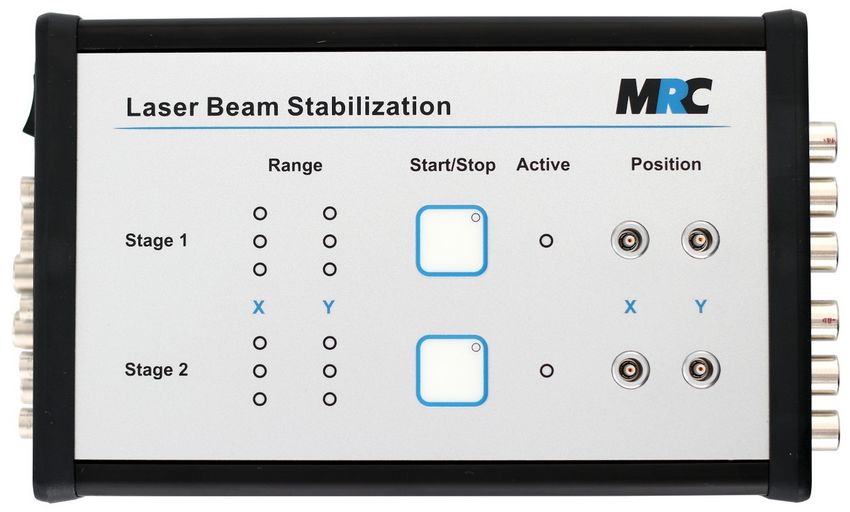
Contents
1. General........................................................................................................................................4
2. System components....................................................................................................................4
3. Specification...............................................................................................................................5
    3.1. Positioning accuracy......................................................................................................................6
    3.2. Relation between measured voltage and actual position................................................................7
4. Optical components....................................................................................................................8
    4.1. Steering mirror mounts...................................................................................................................8
       4.1.1. P4S30.....................................................................................................................................8
       4.1.2. PKS........................................................................................................................................9
       4.1.3. PSH........................................................................................................................................9
       4.1.4. Mirror mounts and adapters for other mirror sizes...............................................................10
    4.2. Detectors......................................................................................................................................10
       4.2.1. Standard 4-quadrant detector................................................................................................10
       4.2.2. Wide intensity detector - 4-quadrant diode with wide intensity range.................................11
       4.2.3. 4-quadrant diodes for UV and IR.........................................................................................11
       4.2.4. PSD detector.........................................................................................................................12
    4.3. Vacuum adaptions........................................................................................................................13
    4.4. Optical filters................................................................................................................................13
5. Installation and operation.........................................................................................................14
    5.1. Brief “step-by-step” instruction....................................................................................................14
    5.2. Introduction..................................................................................................................................14
    5.3. Set-up of optical components.......................................................................................................15
    5.4. Inputs and outputs........................................................................................................................17
    5.5. Intensity adjustment.....................................................................................................................18
       5.5.1. Adjustment of sensitivity with 4-QDs..................................................................................18
       5.5.2. Adjustment of sensitivity with PSDs....................................................................................18
       5.5.3. How to replace the optical filters in the detector housing....................................................19
    5.6. Direction coding of detector outputs............................................................................................19
    5.7. Optimisation of laser beam position on detectors.........................................................................19
    5.8. Adjustment and read-out of the proportional element (P factor)..................................................20
6. Operation and safety features...................................................................................................21
    6.1.   Power level and position display..................................................................................................21
    6.2.   Low power switch-off..................................................................................................................21
    6.3.   Switch-on activity delay...............................................................................................................21
    6.4.   Controller status signal (interlock)...............................................................................................21
    6.5.   Bandwidth limitation switch........................................................................................................22
7. Option: Sample&hold circuit (“ADDA“).................................................................................22
    7.1.   Technical specification.................................................................................................................23
    7.2.   Modes of operation.......................................................................................................................23
    7.3.   Configuration and start of operation.............................................................................................23
    7.4.   Performance.................................................................................................................................25
8. Option: Serial interface (USB, RS-232 or Ethernet)................................................................28
9. Option: External activation.......................................................................................................29
10. Additional inputs and outputs (Options).................................................................................29

Manual - Beam Stabilisation System Compact                     version 13 – 15-February-2021                                                page 2 of 36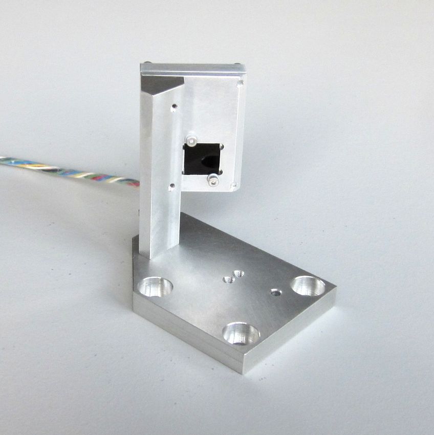
10.1.    Direct drive of Piezo actuators („Drive Actuator“)....................................................................29
    10.2.    Voltage offset inputs to move the target position on PSDs (“Adjust-in”)..................................30
    10.3.    Intensity outputs at controller.....................................................................................................30
    10.4.    Range outputs for monitoring applied Piezo voltages................................................................31
11. Drawings.................................................................................................................................31
    11.1.    Detector housing........................................................................................................................31
    11.2.    Mirror mount P4S30...................................................................................................................32
    11.3.    Mirror mount PKS......................................................................................................................32
    11.4.    Mirror mount PSH......................................................................................................................33
12. Cables.....................................................................................................................................33
    12.1. Standard cables...........................................................................................................................33
    12.2. Additional cables........................................................................................................................33
13. Troubleshooting......................................................................................................................34
    13.1.    No signals on display.................................................................................................................34
    13.2.    No signals on detector................................................................................................................34
    13.3.    The laser beam is not correctly positioned.................................................................................34
    13.4.    The steering mirrors make exceptional noise.............................................................................34
    13.5.    Laser position is not stable.........................................................................................................35
14. Safety......................................................................................................................................35
15. Check list for laser data..........................................................................................................36
    15.1. Laser data...................................................................................................................................36
    15.2. Set-up data..................................................................................................................................36
    15.3. Mirrors.......................................................................................................................................36
16. Contact....................................................................................................................................36

                                                Subject to change without prior notice

Manual - Beam Stabilisation System Compact                     version 13 – 15-February-2021                                                page 3 of 36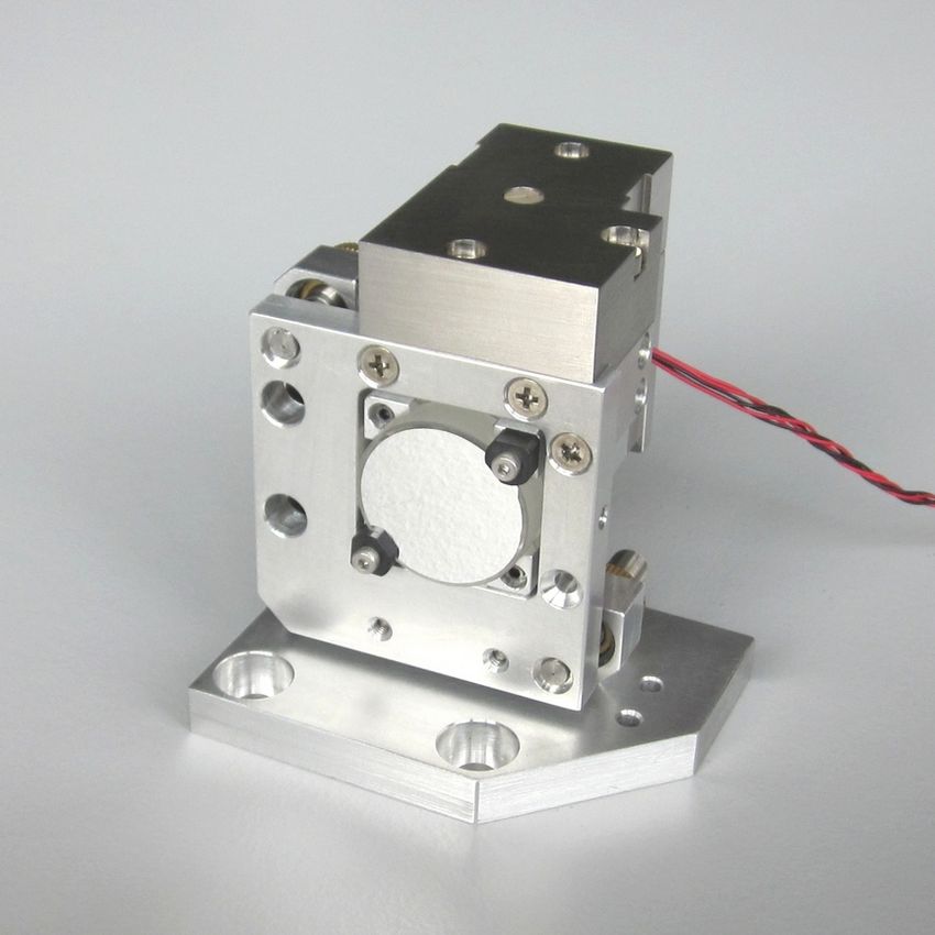
1. General
The Compact laser beam stabilisation
compensates for vibrations, shocks, thermal
drift, or other undesired fluctuations of the laser
beam direction. The system should be applied
whenever laser fluctuations or movements of
optical components occur but a high precision
and stability of the beam direction is required.
The desired position of the laser beam is
defined by a 4-quadrant-diode (4-QD) or a PSD.
For that purpose a small portion of laser power
transmitted through a high-reflective deflection
mirror is sufficient.
Figure 1: Principle of laser beam stabilisation
The closed-loop controller continuously
determines the deviation of the laser beam from
the desired position and drives the fast actuators in that way that the steering mirrors stabilise the laser
beam in the desired position.
The system is available in two different models. The 2-axes system comprises one detector and one
steering mirror and controls the laser beam in two axes. Thus, the laser beam is fixed in one position but
the beam direction can change. The 4-axes system combines two detectors and two steering mirrors in
order to detect the laser beam at two distant positions. Thereby both, position and direction are fixed.
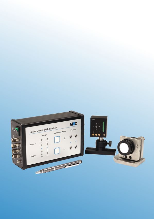
2. System components
The laser beam stabilisation utilizes optoelectronic components (steering mirrors, detectors) as well as
electronic modules. We offer different types of actuators and detectors. For more details please check the
specification in section 3 and the photos in section 4.
Figures 2, 3, and 4 (from left to right): Steering mirror with Piezo drive (version P4S30, 1 inch),
detector with position and intensity display (horizontal orientation), detector (vertical orientation)
Manual - Beam Stabilisation System Compact version 13 – 15-February-2021 page 4 of 36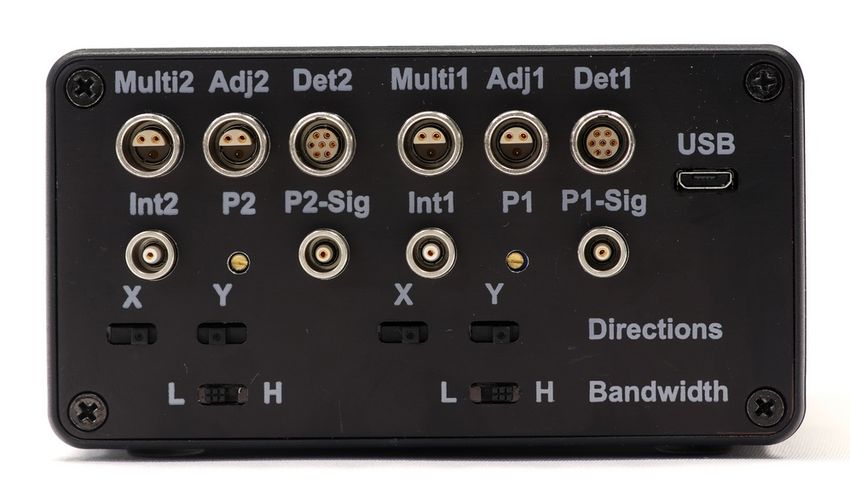
The system electronics (controller, amplifiers, power supplies) is fully integrated into a single compact
housing. It is powered by a standard 12 V wall power supply.

                                     Figure 5: Keyboard and connectors on top panel

     Figure 6: Power input and output connectors                    Figure 7: Input connectors, P factor adjustment
                     on left side                                              and switches on right side

3. Specification
Optical parameters
Wavelength                                     320 to 1,100 nm, UV and IR detectors are also available
Repetition rate                                any rate or cw
                                               For repetition rates < 300 Hz, operations with single pulses or
                                               laser off-times we offer an additional sample & hold circuit, see
                                               also note 1
Laser beam diameter                            < 6 mm (1/e²), see also note 2
Height of laser beam                           45 mm for PKS, 39.5 mm for PSH, 40 mm for P4S30
                                               (Please ask for adapters if you need other heights.)
Mirror diameter                                1" (standard), 1.5'', 2'' and other mirror diameters possible
Mirror thickness                               1/4" or 1/8" (recommended)
Controller housing dimensions
wxhxd                                          166 x 106 x 56 mm3

Manual - Beam Stabilisation System Compact         version 13 – 15-February-2021                              page 5 of 36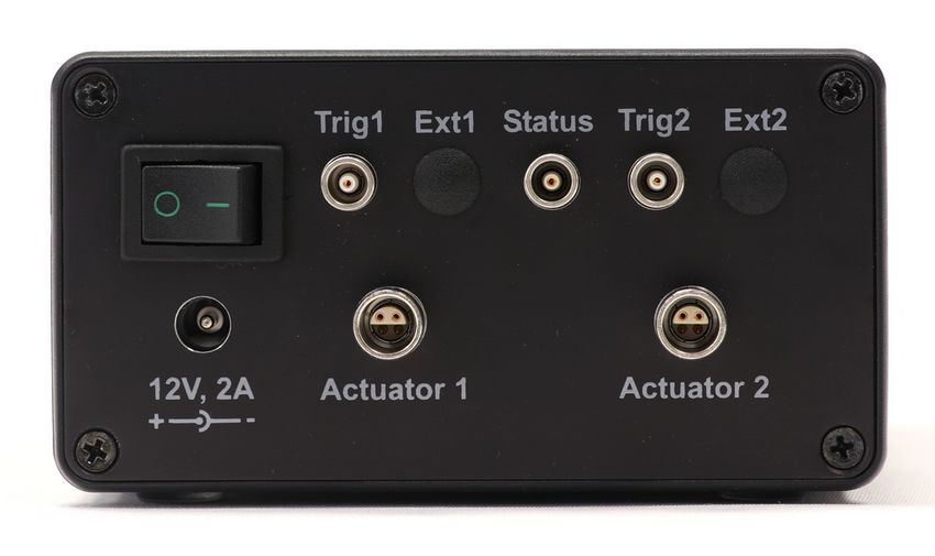
Control features
Power level display                          LED line with 10 elements on the backside of the detector
Position display                             LED cross on the backside of the detector
Variable intensity gain                      Continuous, adjustable with potentiometer (1:6)
Low power switch-off                         Power level falls below 10% of saturation power
Switch on activity delay                     300 ms
Connectors at controller unit
Actuator                                     LEMO 0S series
Detector                                     LEMO 0B series
Controller status signal (interlock)         LEMO 00 series
x, y position output                         LEMO 00 series
Power supply                                 12 V / DC pin-and-socket connector

Notes:
   (1) A description of the sample & hold circuit is given in section 7 of this user manual.
   (2) In case the beam diameter is larger than 6-8 mm, a lens in front of the detector can be used. For
       larger beam diameters adapters for 1.5'', 2'' or other sizes are available (see also section 4.1.4).

3.1. Positioning accuracy
The positioning accuracy depends on several parameters:

• Optical distance between steering mirror and detector: The accuracy is higher for larger distances.
  Therefore a large distance should be chosen. The first steering mirror should be placed close to the
  fluctuation source.
• Beam diameter: Having the same absolute change of laser beam position, a smaller diameter leads to
  stronger power differences on the quadrants of a 4-QD and therefore a steeper control signal. That is
  why laser beams with smaller diameter can be positioned with higher accuracy.
• Intensity: The resolution of the detectors further depends on the intensity hitting the sensitive area.
  This can be varied by an appropriate choice of optical filters and optimised electronically (see also
  section 5.5).
• Repetition rate and pulse duration: The controller bandwidth can be optimised for different laser
  parameters. Higher bandwidths lead to a faster reaction and therefore higher accuracy in case of fast
  fluctuations.

Note: The system uses the intensity centre of the transversal laser beam profile. It does not reduce
fluctuations of the laser beam profile itself.

The position signals of the detectors can be read out with the position outputs on the front panel of the
controller.

Position outputs x, y
Description                                  4 outputs: beam position (stage 1) and (stage 2)
Signal                                       Analog, - 5 V … + 5 V
Connectors                                   LEMO 00 series

In figure 8 the typical resolutions of the 4-quadrant detectors are displayed. The example shows that a
resolution of better than 100 nm on the detectors can be achieved with an appropriate choice of
parameters. The angular resolution can be determined from these data with respect to the respective arm
lengths.

By the use of the material Invar with a very low coefficient of thermal expansion the detectors are
stabilised against temperature variations which ensures that the accuracy is maintained over long term.

Manual - Beam Stabilisation System Compact      version 13 – 15-February-2021                       page 6 of 36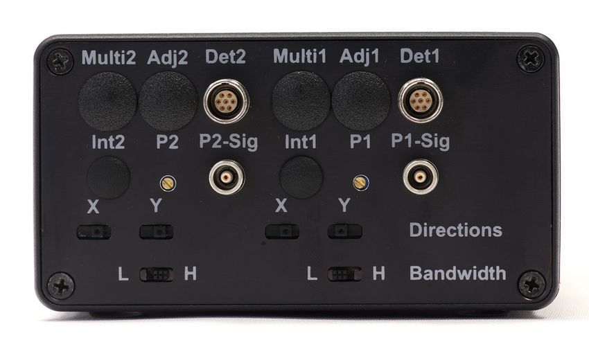
Figure 8: Resolution of a 4-quadrant diode irradiated by a red He-Ne laser
                                  with different beam diameters and laser intensities

The actuators are controlled with an analog signal so that the positioning is not restricted to separate
steps. The positioning accuracy of the Piezo elements are specified as < 2 nrad (PKS) and 4 nrad (PSH).

3.2. Relation between measured voltage and actual position
The position signals are given as voltages. The following formulas allow to convert the voltages into
actual positions.

4-quadrant detector
The beam diameter must be determined. Then the deviations of the positions in µm can be approximated
with the following formula which is valid as long as the beam is near to the centre of the 4-quadrant
diode:

                                                            D [ µm] x [V ]
                                                x [µm] =       π ⋅ I [V ]

Where x is the x position signal measured in volts or calculated in µm. The same calculation can be
made for y. D is the Gaussian beam diameter (1/e 2) and I is the measured intensity signal. For a more
precise calculation or if the beam is further away from the centre, the following formula can be used.
Here erfinv() is the inverse error function:

                                                        D [µm]           x [V ]
                                             x [µm] =          ⋅erfinv (        )
                                                         2⋅√ 2           I [V ]

In case of non-Gaussian beams or to obtain the exact relation, you have to perform a calibration by
means of a micrometer stage.

Manual - Beam Stabilisation System Compact         version 13 – 15-February-2021                   page 7 of 36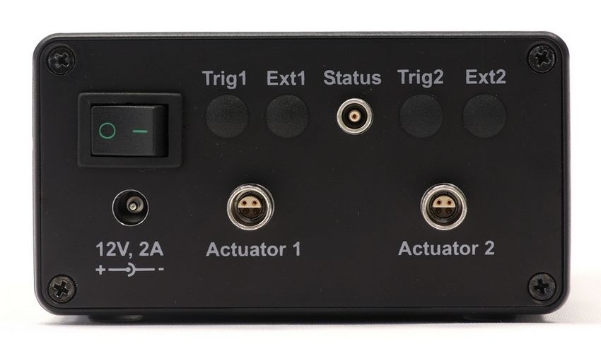
PSD detector
In case of PSDs the relation between voltage and position is almost linear. Here you can use the
following ratio (similarily for y):

                                                             x [mV ]
                                             x [µm] =
                                                           (1.2 ±0.03)

4. Optical components
4.1. Steering mirror mounts

4.1.1. P4S30
The P4S30 has a comfortable tilting range of ± 2 mrad mechanically, which means ± 4 mrad optically. It
is also recommended for larger mirrors (> 1'').

             Figure 9: P4S30 with 1.5'' adapter on           Figure 10: P4S30 with 4'' adapter on stiff mount
                       adjustable mount

Compared to the PKS and PSH mounts with 2 integrated Piezo stacks, it has 4 Piezo stacks resulting in a
higher stiffness and higher resonant frequencies. Thus, the P4S30 can work with higher stabilisation
bandwidths. The P4S30 does not have a free aperture to place a detector behind its mirror.

Specification                                P4S30
Tilting range                                4 mrad (± 2mrad) mechanical, 8 mrad optical
Coarse adjustment (manually)                 ± 4.5°
Piezo stacks                                 4 Piezo stacks integrated
High resonant frequencies                    > 1,200 Hz (with 1'' mirror)
                                             ~ 300 Hz (with 2'' mirror)
High stabilisation bandwidths                > 400 Hz (with 1'' mirror)
                                             > 100 Hz (with 2'' mirror)

Manual - Beam Stabilisation System Compact      version 13 – 15-February-2021                             page 8 of 36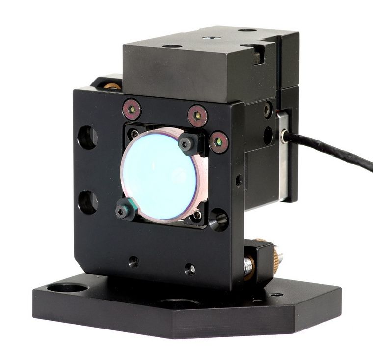
4.1.2. PKS
The mirror mount PKS has a tilting range of ± 0.5 mrad which is smaller than the range of the PSH and
P4S30 mounts (see sections 4.1.3, 4.1.1). In comparison, it offers a wider free space behind the mirror so
that a detector can be placed behind the mirror to detect the leakage. The free aperture is 13 mm. The
mount can be adjusted manually for coarse adjustment. Figure 11 shows a photo of this mount.

Specification                                  PKS
Tilting range                                  1 mrad (± 0.5 mrad) mechanical, 2 mrad optical
Coarse adjustment (manually)                   ± 2°
Piezo stacks                                   2 Piezo stacks integrated
Resonant frequency                             ~ 700 Hz (1'' mirror, mirror thickness 1/8'')

                                  Figure 11: Steering mirror mount PKS with 1'' mirror.
                                       The blue arrows point to the x and y labels

4.1.3. PSH
The mirror mount PSH has a wider tilting range of ± 1 mrad. It can also be adjusted manually for pre-
adjustment to the zero-position.

         Figure 12: Steering mirror mount PSH with                   Figure 13: Steering mirror mount PSH with
                          1'' mirror                                          adapter for 1.5'' mirror

Manual - Beam Stabilisation System Compact         version 13 – 15-February-2021                           page 9 of 36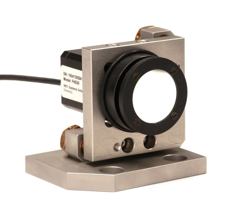
Specification                                 PSH
Tilting range                                 2 mrad (± 1 mrad) mechanical, 4 mrad optical
Coarse adjustment (manually)                  ± 5°
Piezo stacks                                  2 Piezo stacks integrated
Resonant frequency                            ~ 840 Hz (1'' mirror, mirror thickness 1/8'')

Notes:
     •      The movable top plate of the Piezo elements is sensitive to mechanical forces. Please avoid the
            impact of strong forces or torsional moments on it. The Piezo stacks are attached to this plate.
     •      If you intend to remove the 1.5'' adapter you should be especially careful. We can provide a
            specific instruction and a tool for this purpose.

4.1.4. Mirror mounts and adapters for other mirror sizes
Our standard mirror mounts have 1'' mirror holders. The PKS mount is also available for 0.5'' mirrors.

Anyway, our beam stabilisation system can also drive mirrors with larger dimensions. For such mirrors
the system is equipped with specific Piezo-driven actuators and mounts, where the design is optimised
with respect to control speed and tilting range. For 1.5'' mirrors, the PSH and P4S30 steering mirror
mounts can be used. Especially for mirrors with diameters of 2'' or 3'' we recommend the P4S30 mount.
It works with four mutually clamped Piezo stacks and therefore yields a higher dynamic.

Note: With larger mirror masses the bandwidths can be lower than with standard components.

4.2. Detectors

4.2.1. Standard 4-quadrant detector
Figure 14 shows the front side with the detection area of the standard 4-quadrant diode. Figure 15 shows
the rear side of the detector with the LED cross and line and the connectors.

         Figure 14: Standard detector (4-quadrant                     Figure 15: Rear side of the standard detector
         diode with sensitive area of 10 x 10 mm2)

Manual - Beam Stabilisation System Compact           version 13 – 15-February-2021                             page 10 of 36
Specification
Detector type Si 4-quadrant diode
Wavelength range 320 – 1,100 nm
Bandwidth Up to 100 kHz
Sensitivity range ~ 10 µW - 165 µW @ 520 nm, cw (using the intensity potentiometer)
Detection area 10 x 10 mm²
Dimensions
Housing (w x h x d) 40 x 49 x 23.9 mm3
Optical filter 11.9 x 11.9 mm2
Further functions
Power indication LED line with 10 elements on the backside
Position display LED cross on the backside
Connectors
x, y, intensity outputs MCX
Power supply 12 V / MCX
4.2.2. Wide intensity detector - 4-quadrant diode with wide intensity range
In some applications the laser intensity is varied or modulated over wide ranges. The performance of the
wide intensity detector is fully independent of the intensity. The signal amplification automatically
adapts to the changing intensity. The intensity can vary by a factor of >1,000 without the need of
exchanging the optical filters. External signals or user interactions are not required. The signal-to-noise
ratio is not significantly changed over the entire intensity range, so that the stabilisation system reaches
the maximum resolution. The function of the power level display is unchanged compared to the standard
4-quadrant detector. I.e. it can still be used to support the selection of the optical filters. In contrast, the
potentiometer as described in section 5.5 is omitted.
Advantages:
• dynamic range / intensity range: 3 decades
• less noise compared to standard 4-QDs
Specification
Bandwidth < 10 kHz
Signal scaling 9 mV / µm (typical for 1 mm beam diameter)
Sensitivity range ~ 5 µW – 5 mW (@ 520 nm, cw)
Reproducibility over the complete intensity range 10 mV (with 1 mm beam diameter ~ ± 1 µm)
All other specifications are the same as for the standard 4-quadrant detector.
Note: Due to the wide intensity range it is possible to detect even lowest laser powers. Therefore,
depending on the selection of the optical filters, the detection signal can be affected by ambient light.
4.2.3. 4-quadrant diodes for UV and IR
For lasers with UV and IR wavelengths we offer 4-quadrant-diodes with different sensitive areas and the
following specs:
Specification UV 4-QD 3x3 IR 4-QD IR 4-QD Germanium
InGaAs
Wavelength range 190 - 1,000 nm 900 - 1,700 nm 800 - 2,000 nm
Sensitive area 3 x 3 mm2 Ø = 3 mm 5 x 5 mm2
Manual - Beam Stabilisation System Compact version 13 – 15-February-2021 page 11 of 36Figure 16 shows a photo of the sensor side of the UV 4-quadrant diode 3x3.
Figure 16: UV 4-quadrant diode with sensitive area of 3x3 mm2
4.2.4. PSD detector
As an alternative to our 4-quadrant diodes we offer a PSD (position sensitive device) with the following
specs:
Specification VIS PSD
Wavelength range 320 - 1,100 nm
Sensitive area 9 x 9 mm2
In contrast to the 4-quadrant diode the PSD has a continuous measurement area. This leads to two
possible advantages:
1) The sensitive area is not divided by a gap. Therefore, the PSD can be used in case of very small
beam diameters or focused beams (depending on the resulting power density, especially for
pulsed lasers).
2) Whereas with the 4-quadrant diodes the target point is usually defined by their centre, in case of
the PSDs any other point on the sensitive area can be chosen as a target point.
Applications
If you use the PSDs instead of 4-quadrant diodes, the position detection is not limited to the centre as it
is with 4-quadrant diodes. By adding a voltage to the signal of the PSD the target position where the
laser beam shall hit the PSD can be moved. Still, the beam stabilisation will provide full stabilisation of
the beam position, but the position itself can be manipulated. The external signal can be applied to the
system via the “Adjust-in” functionality described in section 10.2.
This feature can be used for different applications, e.g.:
• Place the PSDs before the laser is finally adjusted. Then adjust the laser and read out the target
position. Feed back the voltage for the new target position. The system will then stabilise the
laser beam onto this position.
• Place the PSDs before the laser is finally adjusted. Then move the position on the detectors by
changing the offset voltage until you have the optimal laser adjustment.
• Move the laser beam to different points (or along a pattern) by moving the set point for the beam
Manual - Beam Stabilisation System Compact version 13 – 15-February-2021 page 12 of 36position on the PSDs. You can vary the laser beam direction with highest resolution and it is still
stabilised.
Notes:
• If we equip the beam stabilisation with PSDs but no further measures, we use the electronic
centre (defined by a voltage of 0V for x and y position) as the target position.
• The position vs. voltage characteristics of a PSD is usually not linear. Therefore, a calibration
should be performed if the target shall be moved on a desired path.
Please consider the additional input and output options of sections 10.2 and 10.3 which can further
improve the functionality of stabilisation systems with PSDs.
4.3. Vacuum adaptions
Both, the detectors and the actuators can be adapted for use in vacuum. In case of the actuators, this is
possible for vacuum pressures down to 10 -11 mbar. But this is an extreme value. In case you intend to
place some components in vacuum please let us know the conditions so that we can discuss and offer the
required measures. Some measures (choice of materials, cables, sealing) are mainly focussed to avoid
degassing and depend on the pressure. Others are important to protect the components themselves.
Note:
• The controller itself should not be placed in vacuum.
• The vacuum compatible detector does not have the LED displays on the backside. Therefore
additional intensity outputs are integrated in the controller box.
Figure 17: Vacuum compatible detector Figure 18: Vacuum compatible PSH actuator
4.4. Optical filters
We usually offer to integrate a pair of optical filters in front of each sensor. The filters have a size of
11.9 x 11.9 mm2 and fit into the provided slot in the detector housing.
Manual - Beam Stabilisation System Compact version 13 – 15-February-2021 page 13 of 365. Installation and operation
5.1. Brief “step-by-step” instruction
The following steps shall assist you during the first startup of the beam stabilisation. The following
sections will then explain the single steps more comprehensively.
1) Before use: The components should be stored in a dry environment for at least 24 hours.
2) Robust set-up of optical components (steering mirrors and detectors): The centres of the
detectors define the beam position. The detectors can be placed directly behind mirrors.
Alternatively, a small portion of the beam can be deflected to the detectors by means of a beam
splitter.
3) Cable connection: First mirror with output Actuator 1, second mirror with Actuator 2. First
detector with input Det1, second detector with input Det2.
4) Switch on power supply (switch on the left side of the housing): Thereupon the four green Range
LEDs will shine at the controller box.
5) Adjustment of intensity on detectors (by means of the potentiometer and if necessary exchange
of optical filters): In the best case 9 LEDs should shine.
6) Pre-adjustment (with non-activated control stages): Adjustment of the laser beam onto the
detectors. After this step no red LEDs of the position display (LED cross) should shine.
7) Direction coding: Activation of control stage 1. If red Range LEDs are shining on the controller
box the switch position for x or y direction should be changed (see section 5.6).
8) Direction coding according to step 7, now for stage 2.
9) Fine-tuning for control stage 1: Deactivate both control stages (Active LEDs do not shine). Then
follow the description in section 5.7 until the x and y position outputs are close to 0 V.
10) Fine-tuning for control stage 2: Activate stage 1 (stage 2 is still deactivated). Then proceed
according to section 5.7. After that the Piezos will have the widest range in each direction.
11) P-factor adjustment according to 5.8. Turn potentiometers P1/P2 clockwise until the system
starts to oscillate. Then turn the potentiometers back far enough to ensure an oscillation-free
operation.
12) For the stabilised operation of 4 axes activate both stages.
5.2. Introduction
The system operation can be described best with reference to figures 5 to 7. The top panel in figure 5
shows the keyboard and the position signal outputs for two pairs of detectors and actuators (“stage 1”
and “stage 2”). Each stage can be switched on and off independently by pressing the Start/Stop button. If
the stage is started the small LED in the top right corner of the button is shining. The Range display
shows whether or not the steering mirrors are within the available capture range. The Active LED is
shining whenever the control stage is active. This is the case whenever the Start/Stop button has been
pressed and the laser power on the detectors has the right level.
The Position outputs on the top panel can be used to read out the current position of the laser beam on
each detector (x and y).
Notes:
• Whenever the Start/Stop button is pressed (and the Active LED is on) the actuators start to move
from the zero position and then respond to the controller input.
Manual - Beam Stabilisation System Compact version 13 – 15-February-2021 page 14 of 36• If a Range LED is shining red, this does not automatically mean that the beam is not stable. But
it indicates that no further tilt of the respective steering mirror is possible although it might be
necessary.
• If the power on the detectors is too low the actuators are driven to the zero position (and the
Active LED is off). This is due to the low power switch off that was implemented for safety
reasons (see section 6.2).
Figures 6 and 7 show both sides of the controller box with the connectors, the P factor adjustment and
the switches for the Directions and the Bandwidth selection. The cables for the actuators are connected
on the left side. The cables coming from the detectors are connected on the right side.
The description of the adjustment and read-out of the P factor is given in section 5.8. The Directions
switches enable a coding of the x and y directions of each controller stage. They are connected with Det1
and Det2, respectively. The performance is further described in section 5.6. The function of the
bandwidth limitation switch is explained in section 6.5.
The Status signal output can be used as an interlock or to drive a shutter (see section 6.4).
Note: The Piezo elements have a large electrical capacity. That is why the cables should not be
disconnected as long as the Piezo elements are charged. I.e. you should always switch off the power of
the stabilisation system on the left side of the panel and then wait for a few seconds before you
disconnect the actuator cables.
5.3. Set-up of optical components
The optical components (steering mirrors and detectors) can be configured in variable arrangements for
different applications.
The detectors can be placed behind high-reflection mirrors. They are very sensitive and can work with
the leakage behind the mirrors. This has the advantage, that no additional components are required in the
beam path. Alternatively, it is possible to use the reflection of a glass plate or a beam splitter. The latter
can be necessary for lasers with larger beam sizes where the actuator would constrain the transmission.
In any case, the centres of the detectors should be positioned in that way, that they define the desired
laser beam direction. The target positions on the PSD detectors can be different from their centres. For
further information please refer to section 4.2.4. The first actuator should be placed close to the laser or
the last source of interference. The last detector should be placed close to the target.
Note: Take care for a robust mechanical mounting of the optical components. If possible the delivered
components should be directly tightened to an optical table without further positioning equipment (like
height adjustment). If there are oscillating components with resonance frequencies within the control
bandwidth in the set-up, such resonances can provoke oscillations of the system at that frequency.
The following figures 19-23 show a selection of possible arrangements. These examples are
demonstrated with the 4-axes system with two detectors. However, they can be applied in similar
configurations for the 2-axes system with only one actuator and one detector.
• Figure 19 shows a typical 4-axes set-up of the system where the laser beam hits the optical
components in the following sequence: steering mirror, combination of steering mirror and
detector, mirror with detector.
• Figure 20 shows a similar set-up where additional lenses are placed in front of the detectors.
Further, a beam splitter is integrated in the beam path. This set-up might be better for lasers with
large beam diameters.
Manual - Beam Stabilisation System Compact version 13 – 15-February-2021 page 15 of 36• In figure 21 a lens is placed in front of detector 2 in order to improve the angular resolution. In
this case, the distance between lens and detector should be the focal length of the lens. The focal
length itself should be chosen in that way – depending on the beam diameter – that the focal spot
is not too small. In case of 4-QDs the beam should still have a diameter on the sensor area of
> 50 µm, so that it hits all quadrants of the diode. (The gap between the quadrants of our
standard 4-QD is 30 µm.)
• Figure 22 shows a variation of 21 where both detectors are placed behind the same mirror. In
order to measure both, the beam position and the direction at the same point, a lens is placed in
front of detector 2.
• Figure 23 finally shows a different arrangement where the 4-axes system is used as two 2-axes
systems, i.e. the two stages of the controller are used to separately stabilise two independent
beam lines.
Figure 19: Typical sequence of components for Figure 20: Set-up as in 19, with an additional
the 4-axes stabilisation: Detector 1 stabilises the beam splitter and a lens in front of detector 1
beam position on actuator 2. Detector 2 then and an additional lens in front of detector 2
defines the beam position at a separate point and (Often used for lasers with larger beam
hence the direction. diameters)
Figure 21: Set-up as in 19, but a lens is used to Figure 22: This set-up shows a variation of figure
discriminate the angle by means of detector 2. 21. Both detectors are placed behind the same
This can be of advantage in case of restricted mirror in order to measure both, the beam position
space with small distances between the optical and the direction at the same point. A lens is
components. Detector 2 must be placed in the placed in front of detector 2 which discriminates
focal plane of the lens. for the angle.
Manual - Beam Stabilisation System Compact version 13 – 15-February-2021 page 16 of 36Figure 23: Set-up of a 4-axes system used as two 2-axes systems. With this set-up the position of two independent
lasers can be stabilised with one controller.
Note: In some cases in set-ups where the distance between the actuators 1 and 2 is rather small a
positioning error can occur. This is the case if detector 1 is not placed sufficiently close behind actuator
2. A lens in front of detector 1 can eliminate this positioning error. The lens and the distances should be
chosen in a way that the front surface of the mirror is imaged on the detector. The distances and the focal
length f of the lens can be calculated with the lens equation 1/f = 1/b + 1/g. While g is the distance
between the mirror's surface and the lens, b is the distance between the lens and the detector surface.
5.4. Inputs and outputs
The first steering mirror (figure 2) is connected to the Actuator 1 output. The second steering mirror is
connected to Actuator 2.
The connection of the detectors to the controller unit is made by a LEMO cable with a length of 4 m and
an adapter cable that splits the LEMO cable into four separate cables. These cables are connected to the
detectors according to the following rules: The x and y lines have to be connected in accordance to the
orientation of the detector housing. If the detector is oriented in vertical orientation as shown in figure 4,
the x line has to be connected to the x output and the y line to the y output. If the detector is turned by
90° to a horizontal orientation as shown in figure 3, the x line has to be connected to the y output and the
y line to the x output. At the other end, the LEMO cables of the detectors are connected to the respective
detector inputs at the controller module.
Note:
• The PKS mirror mounts can be mounted in two orientations rotated 90° to each other. On
delivery, they are labelled so that the x-axis performs the horizontal tilt and the y-axis the
vertical tilt. Should you ever change the orientation yourself, please ensure that the horizontal tilt
is always connected to the x input and the vertical tilt to the y input of the controller electronics.
• In case of the 2-axes system you can either use the first or the second stage for stabilisation.
Manual - Beam Stabilisation System Compact version 13 – 15-February-2021 page 17 of 365.5. Intensity adjustment
5.5.1. Adjustment of sensitivity with 4-QDs
To make sure that the detectors operate in the linear range, the power level can be adjusted by tuning the
potentiometer for intensity variation (see figure 24). For that purpose, switch on the system (Power on)
and inactivate the closed-loop control (Start/Stop button switched off, green Active-LED and LED on
button off). Then adjust the laser beam onto the detectors in that way that at least 3 but not more than 9
elements of the power level display are shining. The amplification increases by counter-clockwise
rotation. If the intensity on a detector is too high the sensor gets saturated. In this case all LEDs of the
power level display are blinking.
If you do not find an appropriate adjustment you have to exchange the optical filters in front of the 4-
QDs (see section 5.5.3). If the required filters are not available please contact the manufacturer or
distributor.
Notes:
• In a standard delivery we integrate two optical filters in front of the sensor area. These are filters
with a high and a low density for coarse and fine adjustment, respectively. Usually the filter
which is the first to be reached is the low density one.
• Please be aware that the sensor area is quite sensitive. If you want to clean it you should do this
carefully with a lint-free cloth.
Figure 24: 4-quadrant-diode. The arrow points to the potentiometer
for intensity variation (Please use a screwdriver)
5.5.2. Adjustment of sensitivity with PSDs
The only difference to the adjustment of 4-QDs is that the PSDs have small push-buttons instead of the
potentiometer. The adjustment can be carried out with the delivered metal pin by means of soft pushing.
There is a small push-button for each direction behind the bores in the housing (see the arrows in figure
25). With the upper push-button you can increase the gain step by step, with the lower push-button you
can decrease it. There are 64 steps between the highest and the lowest gain. This corresponds to a change
of the sensitivity by a factor of 20.
If you do not find a fitting adjustment, you can exchange the optical filters in front of the PSD sensors.
Manual - Beam Stabilisation System Compact version 13 – 15-February-2021 page 18 of 36Figure 25: PSD detector. The arrows point to the push-buttons of the digital potentiometers
for the gain adjustment (which can be carried out with the delivered metal pin)
5.5.3. How to replace the optical filters in the detector housing
In some cases it can be necessary to exchange the optical filters. The filters are fixed to the housing with
two plastic screws. To replace the filters carefully open the plastic screws. You can use forceps to hold
the screws during the fixation. Usually, the filter with the higher optical density is the one which is
deeper in the slot.
5.6. Direction coding of detector outputs
For any deviation of the laser beam position on a detector the respective steering mirror is tilted in that
way that it adjusts the laser beam back to the desired position. Each control stage makes use of a steering
mirror and a detector as described in sections 5.2 and 5.3. The components that are working together are
identically coloured in figures 19-23. The direction in which the steering mirror must be tilted depends
on the arrangement of detector and steering mirror. It can be changed during the pre-adjustment process
described in section 5.7 in the following way:
There are four switches on the right side of the controller module (see figure 7). These switches stand for
the x and y directions of the control stages Stage 1 and Stage 2. To turn them into the correct position
just switch on the respective stage. If the laser beam is then deflected into an extreme x (horizontal) and/
or y (vertical) position instead of the centre of the detector, you have to toggle the belonging switch.
5.7. Optimisation of laser beam position on detectors
i. Coarse adjustment (Obtaining linear range of steering mirrors):
Activate the controller module (Start button switched on, green Active-LED and LED on button
shining) and adjust the laser beam onto the detectors by means of manually tilting the steering
mirrors until the four Range signals on the Piezo amplifiers are shining green. Now the steering
mirrors are operating in their linear range.
ii. Fine-adjustment (Obtaining zero position and full range of Piezo drives):
Inactivate the controller module (Piezo drives are in zero position, green Active-LEDs are dark)
and adjust the laser beam by means of manually tilting the steering mirrors in that way, that it hits
the centres of the detectors. This can be done by reading out the x and y position outputs of the
controller module or by observing the position display on the backside of the detector module. The
Manual - Beam Stabilisation System Compact version 13 – 15-February-2021 page 19 of 36position outputs deliver a signal that directly depends on the deviation from the target position.
You can easily display these signals on an oscilloscope. The better the correlation of desired
position and zero position of the Piezo actuators, the smaller the position shift after activating the
closed-loop control. It also ensures that the Piezo range is equal for all directions.
After these adjustments the system should show no fluctuations of laser beam position after the last
mirror with detector when the controller is activated.
5.8. Adjustment and read-out of the proportional element (P factor)
Usually the factory settings of the proportional and integral elements of the control loop lead to a very
stable performance of the beam stabilisation system with desired bandwidths. That is why no user
interactions are required to adjust the control loop. However, in specific cases the user might wish to
adjust the control loop for his application. Such cases can e.g. be set-ups with rather long arm lengths.
Since the control loop is mainly influenced by the proportional element, the system offers a direct access
to the P factors of both control stages by means of potentiometers. The potentiometers are located at the
side panel of the controller box (figure 7). They are labelled with P1 and P2. The adjustment can be done
separately for each stage. An increase of the P factor usually leads to an increase of the overall
bandwidth. In order to optimize the performance, we recommend to start with a small P factor and
operate the system in this stable configuration. Then you can increase the P factor by simply turning the
potentiometer in clockwise direction, until the system reaches its stabilisation limits and starts to
oscillate. The potentiometers should then be turned back to a level, where an operation without
oscillations is guaranteed.
Notes:
• The optimal P factors of stage 1 and 2 can differ.
• If the distances of the optical components, the beam diameter, the laser intensity, or other laser
data change, the P factor of the overall system might also change.
The system is also equipped with an interface in the form of analog inputs for a remote setting of the P
factors. The remote adjustment connectors are integrated into the controller box in addition to the
potentiometers. They are labelled with P1-Sig and P2-Sig (figure 7). Whenever a voltage signal is
applied to the remote adjustment, the potentiometers are ineffective. The input voltages can be set
between 0 and 5 V. The interface can also be used to read out the current voltages as set by the
potentiometers.
Specification
Input/output voltage range 0 … +5 V
Connector LEMO 00 series
Cable (optional) LEMO 00 → BNC for each stage, length 2 m, 2 units
Note: The remote adjustment has to be driven with a low impedance voltage source (= 1 MOhm).
Manual - Beam Stabilisation System Compact version 13 – 15-February-2021 page 20 of 366. Operation and safety features
6.1. Power level and position display
The total power on each connected detector is displayed by means of a LED line on the backside of the
detector module. Furthermore, a LED cross on the detector module displays the current laser beam
position. If the laser beam hits the centre of the detector only the green LED of the position display will
shine. In other cases also yellow and red LEDs will shine according to the examples in figure 26.
a) c)
b) d)
Figure 26: Examples for laser beams hitting the detector (orange spots) and the corresponding position display.
The left pictures are shown in a view from the rear side of the housing to the sensor area.
If only green and yellow LEDs are shining the sensor electronics is in the linear range where a direct
correlation between measured signal and position exists. If a red LED is shining too, the correlation is no
more possible due to the principle of 4-QDs. In case of the PSDs, if a red LED is shining, the beam
probably hits an edge of the sensor. Please check if the full diameter of the beam hits the sensor area.
6.2. Low power switch-off
If the total power falls below 10% of the saturation power (only two LEDs of LED line are on) the
controller module automatically drives the mirrors into their zero positions. This leads to the advantage
that the closed-loop control can start from the zero position even if the laser was switched off or blocked.
6.3. Switch-on activity delay
The integrated switch-on activity delay starts the control only some time after sufficient intensity hits the
detector again. This ensures that the control does not start until a reliable control signal is present and the
steering mirrors have reached the zero positions. The Active-LED will not shine during this delay.
6.4. Controller status signal (interlock)
If the system is completely switched off (power-off), the PKS and PSH Piezo actuators tilt the steering
mirror into an extreme position. This is about 0.5 mrad (PKS mount) and 1.0 mrad (PSH mount) from the
zero position. (The P4S30 does not show this behaviour due to its design with 4 Piezo stacks.) However,
the system is equipped with a TTL output that can be used to block or electronically switch off the laser
in order to avoid damage by the misaligned beam. The level is HIGH when the controller module is
active and the steering mirrors are in the correct range or in zero position. It is LOW if the module is
active and one of the actuators is out of range. (If the controller is not active, the level is always HIGH.)
Manual - Beam Stabilisation System Compact version 13 – 15-February-2021 page 21 of 36Note: The criterion for the actuators being "out of range" is that the Piezo voltage reaches 95% of its
maximum or minimum value.
Status signal
Description 1 output for both stages
Signal TTL, low if Piezo is out of range
Connector LEMO 00
Cable (optional) LEMO 00 → BNC, length 2 m
6.5. Bandwidth limitation switch
The controller bandwidth directly influences the quality of the stabilisation. The system can be operated
with two different controller bandwidths. The default setting is the high bandwidth. However, especially
in case of unstable mechanical set-ups or if a mutual interference of the control stages occurs it can be of
advantage to choose the low bandwidth. Therefore a bandwidth limitation switch is integrated in the
controller module (Bandwidth, see figure 7, H = high, L = low bandwidth). The bandwidth can be chosen
independently for both stages.
7. Option: Sample&hold circuit (“ADDA“)
Function: Fix the laser beam during laser off times
In some applications with the laser beam stabilisation the laser beam might be switched on and off
during the operation. In laser off times there is no intensity on the detectors and hence no control signal
for the closed-loop controller. In such situations, the Compact beam stabilisation without additional
measures will drive the Piezo-driven steering mirrors into a defined position, the so-called zero position.
Once the laser is switched on again the stabilisation will start its operation from this position. The zero
position should have been used for the first adjustment of the optical set-up. That is why this is usually a
good starting point for the stabilisation. However, in cases of large drifts of the laser beam in the overall
set-up, the zero position can – at least in the long term – strongly deviate from the required steering
position. Switching on the laser after a time interval without laser beam and resuming of the stabilisation
can therefore lead to an undesired initial spike of the beam position.
With the additional sample & hold circuit in the Compact beam stabilisation system the positions of the
steering mirrors can be fixed for an arbitrarily long time interval without control signal or laser intensity
on the detectors. In that way it is possible to start the control-loop after switching on the laser not from
the zero position but from that latest stabilised position.
The additional sample & hold (S&H) circuit is of special advantage for the following applications:
– In all systems where the laser must be switched on and off several times during the laser process,
e.g. in material processing machines. Even if the system has drifted away from its basic
adjustment, the beam position will start from the last stabilised position after resuming of the
control loop. In this way an oscillation of the beam from the zero position to the desired position
is eliminated and a potential faulty processing of the work piece is prohibited.
– In systems with a very large distance between the steering mirrors and the detectors. These set-
ups bear the risk that a drift changes the adjustment in that way, that the laser beam will no
longer hit the detector in uncontrolled intervals. Thus, it can happen, that the beam stabilisation
can not catch the beam on the detectors after a resuming of the stabilisation when the laser was
switched off for some time.
Manual - Beam Stabilisation System Compact version 13 – 15-February-2021 page 22 of 36– In systems with very low repetition rates or lasers with irregular intervals of laser pulses (or
pulse packages). If the S&H circuit of the beam stabilisation is triggered for each laser pulse, the
beam position will get closer to the desired position with each pulse.
The name “ADDA” is derived from the functional aspect that the actuators' drive signals are first AD
converted and digitally stored before they are subsequently DA converted again and fed to the amplifiers
of the mirror actuators.
7.1. Technical specification
Sample & Hold circuit
Storage principle Digital storage of position data
Sampling rate 25 kHz
Freezing interval Unlimited
Requirement for automatic triggering Minimal laser on time: > 100 ms
Trigger
Signal levels TTL, “high“ for laser on, “low“ for laser off
Connector 2x LEMO 00, separate connectors for stage 1 and stage 2
Cable (optional) LEMO 00 → BNC for each stage, length 2 m, 2 units
Minimal length of trigger signal “high“ tmin ≥ 10 µs
7.2. Modes of operation
Automatic control of sample & hold elements
The beam stabilisation with additional S&H circuit includes an automatic recognition of laser on and off
states. This is done by sampling the intensity on the position detectors. The automatic operation controls
the S&H elements in order to store the signals in laser on times and fix the position of the steering
mirrors during intervals with no intensity.
For this automatic control the laser on intervals or the respective duration of pulse packages must be
longer than 100 ms.
There is no need for the user to provide any trigger signals for this mode of operation.
External triggering of the sample & hold elements
For single laser pulses or lasers with very low repetition rates, modulated cw lasers or pulse trains
< 100 ms the automatic control can not release the stored beam position in due time. In such cases it is
necessary to control the S&H elements by means of external triggering. The requirements for the trigger
signals are described in section 7.3.
7.3. Configuration and start of operation
Cabling
In the operation mode of automatic control there is no need for additional cabling.
If the external triggering is used, the trigger signals have to be fed into the controller box via the
respective LEMO connectors marked with “Trig” (see figure 27). The left connector controls the S&H
function for stage 1 / steering mirror 1. The right connector controls it for stage 2 / steering mirror 2.
Manual - Beam Stabilisation System Compact version 13 – 15-February-2021 page 23 of 36Figure 27: Left panel of controller box with trigger inputs
External triggering
The external triggering enables an accurate timely assignment when the system shall store the position of
the steering mirrors and when the position shall be fixed. This assignment is especially important in case
of single laser pulses. For an optimal function of the S&H circuit there are time restrictions for the
trigger signal which should be met. Figure 28 illustrates the respective tolerances of the trigger signal.
Figure 28: Timing of trigger signal
– Duration of trigger signal: tmin ≥ 10 µs
– Start time of trigger in relation to start of laser on interval: -10 µs ≥ τ1 ≤ 50 µs
– End time of trigger signal after end of laser on interval: τ2 ≤ 1 ms
The electronic requirements for the trigger signals are:
– TTL levels
– Level “high“ when there is laser intensity on the detectors, level “low” when there is no intensity
Manual - Beam Stabilisation System Compact version 13 – 15-February-2021 page 24 of 36You can also read