Looking Closer: A Guide to Making Bird's-eye Views of National Park Service Cultural and Historical Sites
←
→
Page content transcription
If your browser does not render page correctly, please read the page content below
1

Looking Closer: A Guide to Making Bird’s-eye Views of
National Park Service Cultural and Historical Sites
Tom Patterson
US National Park Service, Harpers Ferry Center

Published in Cartographic Perspectives (Number 52, Fall 2005), the journal of the North
American Cartographic Information Society (NACIS).

ABSTRACT

The US National Park Service (NPS) has long used large-scale panoramas, also known as
bird’s-eye views, to portray park sites where buildings and other human-made features
are plentiful. This paper examines these bird’s-eye views, most of which were produced
by nationally renowned contract illustrators in a wide range of artistic styles. Both their
traditional and digital work receive attention. A brief historical review looks at the
antecedents of current NPS products dating back to the Renaissance. The practical second
half of the paper focuses on how the NPS now designs these bird’s-eye views with 3D
software, with an eye toward cost savings. Topics include viewing parameters in a 3D
scene, preparing DEMs, modeling buildings, designing trees, and creating environmental
special effects. Two dozen full-color illustrations supplement the text.

INTRODUCTION

On the afternoon of May 31, 1889, following a night of torrential rain and years of poor
maintenance, South Fork Dam reached its breaking point. The earthen structure gave way
releasing three-kilometer long Lake Conemaugh in a deadly surge of water and debris—
trees, houses, barbed wire, and livestock—that swept through Johnstown, Pennsylvania.
More than 2,200 people died in the disaster, which ranks as the worst inland flood in US
history. The former dam site is now a national memorial managed by the US National
Park Service (NPS). To explain to visitors how the flood occurred, the NPS uses a
sequence of bird’s-eye views showing the dam deteriorating over time, ending with its
failure (figure 1).

Figure 1. Johnstown Flood National Memorial, Pennsylvania. The South Fork Dam as it appeared when
newly constructed (left), in a state of disrepair (middle), and breaching (right). Art by L. Kenneth
Townsend.
2

Bird’s-eye views such as these are commonly a part of the presentations that the NPS
prepares for visitor use. They vividly depict historical events and settings, and give a
panoramic yet intimate view of places in a way that no other graphic, including a
traditional map, can. In our fast-paced, distraction-filled modern world, bird’s-eye views
are a rare commodity for being able to “connect” with park visitors.

In this paper I examine how the NPS designs and produces bird’s-eye views for the
depiction of cultural and historical sites. The range of products includes artistic
illustrations, such as Johnstown Flood—most of the other views deal with cheerier
topics—and products with lines and labels that fall within the cartographic fold. The
primary emphasis is on the digital 3D design and production methods developed by the
NPS in collaboration with our contract illustrators. In the hands of a talented 3D artist,
digital production methods yield bird’s-eye views every bit as visually appealing as those
produced traditionally. How we reached this level of refinement is a story worth telling.

The making of bird’s-eye views is a difficult and poorly understood enterprise. Although
they portray spatial relationships just as any proper map should, they nevertheless are a
niche product on the margins of mainstream cartography. Art, architecture, computer
gaming, movie animation, and the new field of urban simulation all have a stake, perhaps
more deservedly than cartography, in the ownership of this genre. The conventions that
guide cartographers in the making of traditional maps simply do not exist yet for bird’s-
eye views, although research has begun in this area (Haeberling, 2004). It should come as
no surprise then that the people who make NPS bird’s-eye views, regardless of their
professional backgrounds, are by necessity self-taught.

To begin bridging this knowledge gap, the aim of this paper is to provide practical ideas
for those making bird’s-eye views, and to serve as a reference for clients needing to have
them made. Knowing basic concepts and the right questions to ask is essential for all
parties concerned. After beginning with a general discussion of bird’s-eye views, the
pages that follow look at the many design and production issues that go into the making
of a successful view.

BACKGROUND

The somewhat quaint term bird’s-eye view, first coined circa 1600, is apt for describing
the obliquely viewed perspective scenes that I discuss in this paper. They are a variant of
the landscape panoramas painted by the late Heinrich Berann and others, but with the
emphasis on the human environment rather than the natural (Patterson, 2000). Human-
made structures on the surface of the land, such as buildings, fences, and dams, appear
with three-dimensionality and dominate the scene.

Extremely large-scale depiction is another key trait of bird’s-eye views. Notwithstanding
an unfortunate Ruppell’s Griffon Vulture that once collided with an aircraft 11,278
meters over Africa, most birds fly at altitudes less than 1,000 meters, and usually they
stay within a few dozen meters of the ground (Whiteman, see references for URL). This
altitude range is similar to the viewing elevation found on NPS bird’s-eye views, a point
3

much closer to the ground than that of a typical map. For example, cities and towns often
appear on maps as small dots; the sites depicted on a typical bird’s-eye view would take
up at most a mere pinprick of the area within these dots. At these much larger scales even
tiny details, including people and animals, become visible. Keen-eyed readers may have
noticed the horse and carriage crossing the South Fork Dam (Figure 1, middle).

The ease in which readers can identify all features on a bird’s-eye view is one of their
chief advantages over traditional maps. At extremely close range in a scene we recognize
the depicted objects based on observations in our everyday lives rather than the learned
skill of map reading. As the virtual camera moves closer to the ground and the scale
becomes increasingly large, you reach a point where realistic 3D depiction of surface
objects becomes the preferred solution rather than abstract 2D depiction. In some cases
2D depiction is never feasible, for showing a horse and carriage on a dam, for instance.
Most of the visual cues needed for identifying large objects (things that are bigger than
we are) can be found in profile view in the vertical (z) dimension. We identify buildings
by the windows, doors, siding, etc, observed on their exterior walls. How many of us
know what the roof of the building we are currently in looks like from above? More
difficult still, what does the building’s footprint look like on a large-scale plan map?

Bird’s-eye views also can reveal things that are difficult for a contemporary park visitor
to see, such as how a place looked in the past. Possible examples include a crumbling
archeological site portrayed as the vital place that it once was, a historic battle recreated
on a field that today looks more park-like than bloody, and, as we have seen, simulating a
dam break. A special use for NPS bird’s-eye views is showing readers the otherwise
hidden interiors of buildings (figure 2).

Figure 2. Building visualization. (left) The Castillo de San Marcos, St. Augustine, Florida, lifted off its
foundation. (middle) Buildings at Appomattox Court House, Virginia, that no longer exist, shown in
ghosted form. (right) The interior of a barracks at Manzanar, California, revealed in an “X-ray” or cutaway
view. From left to right, art by L. Kenneth Townsend, Chris Casady, and Don Foley, respectively.

Finally, bird’s-eye views go by many names. Among the words commonly mixed and
matched together, often only according to whim, are aero, oblique, panoramas,
perspective, three-dimensional (3D), renderings, scenes, simulations, views,
visualizations, and, last but not least, maps. All are appropriate. In this paper I will
attempt to stick with the term bird’s-eye views. However, for the sake of variety and
brevity I occasionally use the other terms.
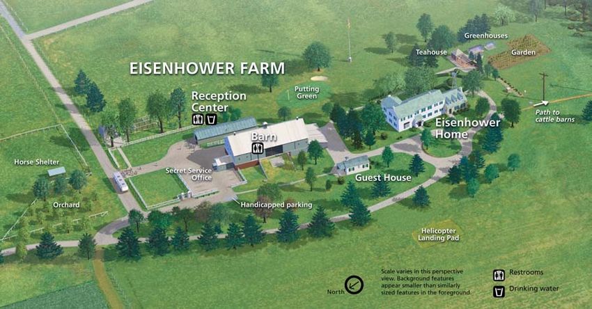
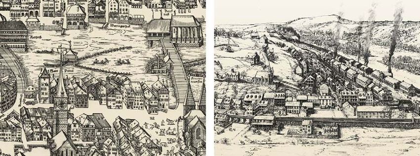
4

Historical perspective

Bird’s-eye views have a long history in mapmaking, and those produced by the NPS are a
part of this continuum. Despite the predominance of planimetric maps today, up until two
centuries ago oblique views were far more common, and the depiction of terrain and
cities often revealed the three-dimensional nature of these features. It is only natural that
early mapmakers drew cities in this manner; that is what the buildings in which they lived
looked like. Perhaps the most famous early bird’s-eye view is a 1502 map of Tuscany and
the Chiana Valley by Leonardo da Vinci. On this oblique map the hills appear in profile
topped with fortified towns. The city maps created in Europe during the Renaissance are
the direct stylistic forebears of some bird’s-eye views made by the NPS today (figure 3).

Figure 3. (left) A 1576 map of Zurich, Switzerland, by Jos Murer. (right) A map showing Harpers Ferry,
West Virginia in 1860, drawn by Richard Schlect circa 1980. Zurich map source: Imhof, 1963.

The decades from the late 19th to early 20th century were the golden era of bird’s-eye
views in the US. As towns and cities grew and became prosperous thanks to
industrialization, it became fashionable and a matter of civic pride to advertise this
newfound economic vitality in the form of oblique panoramic maps. Itinerant
panoramists traveled from town to town primarily in the Northeast and northern Midwest
mapping furiously as they went. Notable panoramists include Thaddeus Mortimer
Fowler, who in his 54-year career generated more than 400 views, and Albert Ruger who
published 60 views in 1869 alone (Hébert, 1984).

Fowler and Ruger did not go up in hot air balloons or strap miniature cameras to pigeons
or kites to gather information for their panoramas. Instead, they stayed firmly on the
ground drafting a street map in perspective based on a grid. Next, they walked through
the town sketching the facades of buildings that would appear from the viewing direction
that they had chosen. Finally, they drafted the final panorama, filling in detail from the
building sketches they made in the field. As we shall see later in this paper, the
techniques used by Mssrs. Fowler and Ruger, overlooking the primitive technology of the
day, have similarities to those of the NPS today. The US Library of Congress maintains
5

an online collection containing some 1,500 bird’s-eye views of cities in the US and
Canada made during the Victorian and Edwardian eras (see references for URL).

As industry in the American heartland waned in the mid-20th century, so too did the
making of classic bird’s-eye views. This relatively quiet period of time, however, did see
the publication of several notable pieces, including an axonometric view of Manhattan
published in 1962 by Bollmann Bildkarten of Germany (see references for URL); David
Greenspan’s detailed battle maps for the American Heritage Picture History of the Civil
War (Catton, 1960); and, artistic illustrations appearing in National Geographic
magazine. The pieces by Greenspan and various National Geographic artists, which
depicted past events and thematic subjects in oblique views, point toward the type of
bird’s-eye views that the NPS would produce in the coming decades.

Today, bird’s-eye views are once again in vogue. If the industrial economy spurred their
production a century ago, the burgeoning tourist economy drives it now. The prevalence
of 3D maps of ski areas and summer resorts highlights this trend. Just as 19th-century
bird’s-eye views were a tool for economic boosterism, we find today that many chambers
of commerce distribute 3D maps (ranging in appearance from cartoonish to glitzy to
elegantly refined) of downtown restaurant and entertainment districts in a bid to attract
more tourist dollars. Bird’s-eye views are also growing in popularity online. The recent
launch of Google Earth now allows users to interactively explore 25 major cities in the
US from any direction and viewing elevation with buildings appearing as blocky 3D
forms. Rival online mapping service MSN Virtual Earth has plans to depict buildings in
urban areas with oblique aerial photographs taken from multiple directions (see
references for URLs).

Whether 3D maps are really better than 2D maps for helping people find things and get
around is not certain and is a topic of current cartographic research (Freundschuh, 2001).
Marketers, however, are more decided about the usefulness of bird’s-eye views. When
selling things, looking good matters.

The NPS uses bird’s-eye views for promotion of a different sort: to foster appreciation of
the cultural and historical heritage of the United States.

TRADITIONAL NPS BIRD’S-EYE VIEWS

The Harpers Ferry Center (see references for URL) is the NPS facility responsible for
making bird’s-eye views, a side product of a much broader mission. The Center creates
interpretive media—a catchall term that includes brochures, indoor and outdoor exhibits,
movies, and multi-media—for the 388 units of the National Park System. Art plays an
important role in this effort. Since its creation in 1970, Harpers Ferry Center has
commissioned nearly 10,000 pieces from hundreds of commercial artists and illustrators,
many with national reputations. The subject matter portrayed by this commissioned art is
as broad as the National Park System itself. In the art collection at Harpers Ferry Center
you can find ink sketches of prehistoric artifacts, a watercolor of a determined John
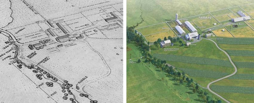
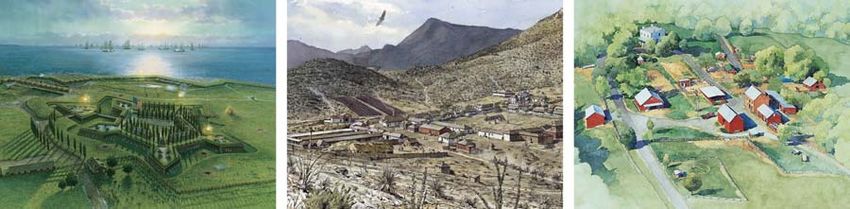
6

Brown holding a pike, and an acrylic collage of the plants and animals found in the
Everglades. It is amidst this visual bounty that one also finds the 200 or so pieces that
qualify as bird’s-eye views.

Traditional art

Many of these artistic works strain even the broadest “big tent” definitions of what a map
is. On some pieces the viewing angle is high and map-like, but on most the angle is
considerably shallower, making spatial relationships difficult to judge. Not that it matters
much. Views of this type are not intended to help visitors get around but to convey an
impression of how a place looked in the past. Non-spatial issues—who, what, and how—
take precedence over where. The most successful of the illustrative views recreate
historical events with vibrant realism. For example, the view of Fort McHenry, Maryland,
depicts the familiar battle imagery contained in the lyrics of the US national anthem
(figure 4, left). A comparison with a stirring martial tune is a tall order for any graphic,
which the bird’s-eye view by L. Kenneth Townsend manages to accomplish, notably.

Depending on the artist and the type of medium used, the style of a bird’s-eye view can
vary considerably, a choice that the NPS makes carefully. Often these styles relate to a
particular genre of art. For example, the luminous and detailed quality of Townsend’s
“Fort McHenry” is reminiscent of countless paintings of heroic battles hanging in
museums throughout the world (figure 4, left). In the muted ink and watercolor
renderings of Richard Schlect it is not too difficult to see parallels with the 19th-century
expeditionary art (figure 4, middle). And the soft watercolors of Greg Harlin strike a
chord of nostalgia for our simpler arcadian past (figure 4, right). We see this style of art
on the cover of catalogues issued by a vendor of outdoor apparel and gear based at
latitude 43° 51’ N, longitude 70° 06’ W.

Figure 4. Some of the varying artistic styles found in illustrative NPS bird’s-eye views. (left) Fort
McHenry, Maryland, by L. Kenneth Townsend. (middle) Fort Bowie, Arizona, by Richard Schlect. (right)
Oxon Hill Farm, Maryland, by Greg Harlin.

The staff at Harpers Ferry Center provides art direction to the artists who transform a
blank sheet of paper into a lavishly rendered bird’s-eye view. To learn more about how
this is done I visited Wood Ronsaville Harlin, Inc. in Annapolis, Maryland, an illustration
studio which does contract work for the NPS (see references for URL). There I met with
Pam Ronsaville, president of the firm, and senior illustrators Rob Wood and Greg Harlin.
7

Like our other contract illustrators, they do not specialize exclusively in the making of
bird’s-eye views but create a range of products that includes natural science, historical,
infographic, and children’s illustrations. Recently they have also begun creating cover art
for popular fiction. Belying these handsome pieces that stir the reader’s emotions,
however, careful research and preparation goes into all of the art that they create with
little left to their imagination. For example, even an artistic book cover derives from
direct visual references, typically photographs taken in the controlled environment of
their studio and composited as a mosaic in Adobe Photoshop. It should come as no
surprise then that when making bird’s-eye views the need for good visual references is
even more important.

Oblique aerial photography is the reference material of choice for making bird’s-eye
views. Greg Harlin photographed Oxon Hill Farm, Maryland, from a helicopter to obtain
the base map he needed to paint the final art (figure 4, right). He supplemented the aerial
photographs with others taken from the ground. When Rob Wood painted a view of
Herbert Hoover National Historic Site, Iowa, obtaining helicopter photography was not
possible so he had to rely instead on an aerial photograph draped on a DEM and viewed
obliquely in a 3D application. Because buildings in 2D aerial photographs do not appear
with three-dimensionality when viewed in a 3D application, Wood had difficulty
visualizing how the final scene should look. He nevertheless managed to pull this off in
the end in his usual polished style.

The actual rendering of the bird’s-eye view takes place in three steps: a rough pencil
sketch, a final pencil sketch, and, finally, the painted art. At all stages of production the
art undergoes review by staff at Harpers Ferry and at the park portrayed in the art. The
entire process progresses in fits and starts and can take more than a year to complete.
Both Harlin and Wood emphasized the importance of visiting a site to “absorb the natural
beauty and history of the area” as an important factor in producing top-notch views.
Deciding just how much or, more importantly, how little texture to put in a scene is key
to a successful project. According to Harlin “I spend a lot of time making it look like I
didn’t spend a lot of time painting the illustration.” Both artists try to imagine themselves
“in the scene” as they paint. When rendering final art they also pay considerable attention
to lighting to accentuate small details and give the overall scene interest and drama.

Map-like views

In addition to this commercial art, over the past 35 years the NPS staff has made about
one dozen map-like bird’s-eye views that are utilitarian in appearance and function. They
serve primarily as devices for orienting visitors and site navigation—where is the visitor
center and how do I get there. To produce these views we traced over oblique aerial
photographs in ink, leaving a framework of casing lines for roads, pathways, trees, and
buildings that were filled with flat colors photomechanically. They look similar to the 3D
maps of college campuses that are so common today. Depending on the availability of
suitable oblique aerial photographs, these products were relatively inexpensive and quick
to make. Moving now to the digital part of this paper, we will see that they are no longer
made with ink at the NPS.
8

DIGITAL NPS BIRD’S-EYE VIEWS

As elsewhere in the cartographic community, at the NPS the transition from traditional to
digital mapping has been our focus for much of the past dozen years. Having started with
small inset maps first, we now make all of our products digitally, including large visitor-
use maps, shaded relief, and even landscape panoramas. We also make map-like bird’s-
eye views—like the inked versions discussed above—digitally. Using Adobe Illustrator
software instead of Rapidograph pens, the NPS has replaced all of these inked pieces
with vector files, also comprised of lines and flat tones. I discuss a variant of this
technique in the upcoming section on budget bird’s-eye views.

Moving beyond simple line drawings, making artistic bird’s-eye views with digital tools
that are comparable in quality to our best traditional pieces has proven to be a more
difficult challenge. Vector drawing applications like Adobe Illustrator can take you only
so far in depicting scenes with artistic refinement and natural realism. For these we have
turned to 3D software, the same tools used to create blockbuster animated movies and
popular computer games. Scenes created with 3D software can contain dappled lighting,
soft shadows, reflective water bodies, atmospheric haze, and organic textures that appear,
for some types of work, completely real to all but the most discriminating viewers.
Nevertheless, 3D software has a major downside compared with other digital techniques;
it is an order of magnitude more difficult to use. Big and complex, these are not the sorts
of applications with which you can occasionally dabble and expect to gain proficiency.
Consider Maya, the 3D application used to create many of the special effects in
Hollywood movies. In the large production shops it is common for the animation
professionals who use Maya to have a single specialty, like modeling, texturing, lighting,
motion, etc (Casady, 2004). Creating 3D special effects is a collaborative effort, as long
film credits show.

As though using difficult-to-use software were not enough, the creation of a bird’s-eye
view in 3D software requires the user literally to build a virtual model of the entire site in
painstaking detail. If you want to see it, you have to model it: scratch beneath any surface
in a 3D scene and you will find a wireframe object. The effort is similar in scope to the
elaborate sound stages built for filming movies or the museum dioramas with displays of
wild animals (of the stuffed variety) placed in front of painted natural backdrops. On a
bird’s-eye view, to distinguish between two buildings—one, say, with a gable roof and
the other with a hip roof—requires building separate models of each building. Depending
on the complexity of the buildings, each may take anywhere from 15 minutes to several
hours to create. Multiply this by perhaps dozens of buildings in a given scene, and the
production quickly becomes arduous.

The creation of bird’s-eye views at the NPS with 3D software occurs both in-house,
mostly for simpler projects, and with the assistance of outside contractors whom we art
direct for larger and more complex projects. Our contractors include notables like Chuck
Carter, best known for his work on the computer game Myst; Don Foley, author of two
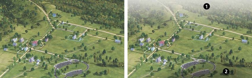
9

books on 3D animation and a frequent contributor to National Geographic; and, Chris
Casady, who worked on the movie Star Wars (see references for URLs). If the output
from 3D software has a visual fault it is the tendency for it to look hyper-realistic—too
smooth, shiny, and simulated. Although this look is desirable for depicting space stations
and sleek new automobiles, it is out of character for historic park sites. Of the NPS
contractors, the work of Chris Casady, despite, or maybe because of his impeccable
credentials on science fiction movies, achieves the painterly look that the NPS seeks in
bird’s-eye views. Through patient hard work, mastery of his preferred software (Bryce),
and an artistic eye, Casady manages to combine human-made and natural features into
thoroughly convincing final scenes. You will see many examples of his work throughout
this paper.

Today one finds many 3D software applications sold to a relatively small pool of users.
Consequently the prices of these applications are generally high, although not as
expensive as they were a few years ago. Nevertheless, Maya Unlimited, a product of
Alias, and one of the pricier 3D applications, will cost you US $6,999. The artists who
provide services to the NPS use a variety of 3D modeling and rendering applications. If
the need arises, sometimes they will use multiple applications on the same project.
Subscribing to the belief that using software creatively is as important as what brand (or
price) it is, I use Bryce 5.0, a $100 application from Daz Productions. There is, however,
one software application used by everyone. The raster art rendered by all 3D programs
inevitably finds its way into Adobe Photoshop for final image enhancement.
Additionally, at the outset of a project, data are prepared in Photoshop for later use in 3D
applications.

For the rest of this paper I attempt to be software agnostic as much as possible. If you
should happen to prefer a software application other than the one that I am discussing, I
invite you to make a mental substitution.

Planning

The design of bird’s-eye views requires considerably more care and interaction with
clients than does the design of a traditional 2D map. A point is reached soon after
production begins at which making even a small change to the basic scene parameters,
for example, shifting the direction of view 10 degrees to the west, means much wasted
work. An analogous situation would be for an architect to give new plans to a builder
after construction has begun. To safeguard against this, the Harpers Ferry Center provides
the park staff with several mockups of a bird’s-eye view to review. A base map loaded
into a 3D application allows easy changes to the viewing parameters should the need
arise. The park staff then decides, with coaching from Harpers Ferry Center, which
preliminary scene best meets their needs—consensus is essential. Work on the final scene
begins only after Harpers Ferry receives written approval to proceed from a person in
authority at the park (figure 5).
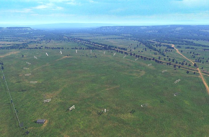
10

Figure 5. A portion of Eisenhower National Historic Site, Pennsylvania. (left) A plan map draped on a
DEM and viewed obliquely in Bryce. The park approved this view as the basis for final production. (right)
The final bird’s-eye view. Art at right by Chris Casady.

Occasionally I encounter a park site that for a variety of reasons is not ideally suited for
depiction as a bird’s-eye view. My advice based on hard-learned experience is not to
force the issue but instead to use conventional 2D mapping. In fact, some projects are
undeserving of any type of cartographic depiction—for example, showing the path from a
parking lot to a nearby visitor center. In this case, people can more easily follow signs on
the ground pointing to the visitor center.

Budget bird’s-eye views

A few words are in order about the fiscal realities of making bird’s-eye views. Although
3D modeling software creates the most elegant bird’s-eye views, the downsides are
production times and costs that are significantly higher than other digital options.
Hollywood studios can afford the expense of 3D production because of the potentially
enormous revenues that films generate. The same applies to computer games. In late
2004 the release of the computer game Halo2 generated US $124 million in sales for
Microsoft in 24 hours. Because production budgets at the taxpayer-funded NPS are
smaller by a factor of several zeros compared to these commercial entertainment
ventures, we use 3D techniques with any eye toward both quality and cost management.
A complex bird’s-eye view created by 3D software costs about the same as an equivalent
view painted traditionally, somewhere between $12,000 and $20,000. One advantage of
3D modeling is the potential for repurposing work as animations or QuickTime Virtual
Reality (QTVR) scenes, which spreads costs over several projects. Nevertheless, until
more economical 3D production methods become available, as they undoubtedly will, for
much of our work we will continue to seek less expensive alternatives, including simply
tracing vector art from oblique aerial photographs.
11

Two less expensive methods of producing bird’s-eye views deserve mention here.

Hybrid method

This involves combining 3D modeling with vector drawing software for production. The
“flying carpet” view of Marsh-Billings-Rockefeller National Historical Park, Vermont, is
an example of such a merger of methods (figure 6, middle). The foundation of the scene
was a square-shaped digital elevation model (DEM) representing terrain viewed
obliquely with 3D software. A rasterized map draped on the DEM, much like a decal on
an automobile bumper, shows roads, trails, and building footprints. The next steps
include rendering the oblique 3D scene, saving it as a 2D Photoshop file, and placing it as
background art in Illustrator. Finally, in Illustrator, the trickiest step was drafting
simulated 3D buildings on top of the building footprints visible on the raster art placed on
the layer below. Even with the aid of reference photographs and perspective grids as a
guide, drawing angled rooflines presents visualization challenges. Ultimately, one must
rely on intuition to accomplish the task.

Photo method

Occasionally an oblique aerial photograph by itself can serve as the final art. The NPS
used this method for making the bird’s-eye views of Fort Stanwix National Monument,
New York (figure 6, right). Faced with spending $15,000 and waiting several months to
have the scene developed using 3D software, we instead hired a photographer and
helicopter to take dozens of high-resolution digital photographs from the air. One of these
shots had the viewing direction, viewing angle, and illumination that we sought.
Including the in-house time spent planning the project, writing contracts, and applying
watercolor artistic filters to the image in Photoshop, the job took only days to complete
and cost just $1,400.

Not every park site lends itself to this production method, however. Fort Stanwix, which
sits in an open field, is not obscured by the large numbers of trees that are typically found
in parks and, more troublesome still, often grow next to buildings. Wintertime
photography when the leaves are off the trees helps but only so much. The decision to use
aerial photography depends on the suitability of the site, access to oblique aerial
photographs, and tolerance for image editing in Photoshop. On the plus side performing
touchups in Photoshop is much faster than modeling 3D scenes completely from scratch.
In the case of Fort Stanwix the NPS was fortunate and only had to remove a few
lingering snow drifts (the photograph was taken in early April) with the Clone (rubber
stamp) Tool in Photoshop.
12

Figure 6. (left) Glen Echo, Maryland, was sketched in Adobe Illustrator using an older inked map as a
guide. (middle) Marsh-Billings-Rockefeller National Historical Park, Vermont, was made from a 3D terrain
base upon which buildings were drawn in 2D in Adobe Illustrator to appear three-dimensional. (right) Fort
Stanwix National Monument, New York, derives from an oblique aerial photograph artistically filtered in
Adobe Photoshop.

3D DESIGN AND PRODUCTION

This final section covers some of the many design and production factors influencing the
making of bird’s-eye views in a 3D software application. Given the great variety of
software used for creating 3D scenes, and how generally difficult they are to use, the
discussion that follows gives an overview of the issues—what you should be doing, more
so than the particulars of how you might do it. I introduce subjects generally in the same
order in which they come up when building a 3D scene. Several of the illustrations
compare examples of good and bad design—a check mark at the top indicates the good
examples.

I will begin this section with a discussion of the viewing parameters that determine the
basic appearance of a 3D scene. Appropriately enough the first step in designing a
successful bird’s-eye view is choosing a good view.

View direction (orientation)

All bird’s-eye views look at sites from a certain direction, for example from southwest to
northeast. Picking the best view direction is a critical concern because, compared to
planimetric maps, bird’s-eye views are less flexible for on-site navigation. As you walk
the winding paths of a park with a printed bird’s-eye view to guide you, the piece cannot
be rotated to the direction you are facing as is possible with a plan map. Try turning
upside down any of the illustrations of a bird’s-eye view that accompany this article.
They just don’t work. What this tells us is that whatever view direction you choose for a
bird’s-eye view—the possible choices span 360 degrees—had better meet the orientation
needs of most park visitors most of the time.

For maps of large-scale sites the NPS has a long-standing convention of using an
orientation that matches the direction from which visitors enter the site (figure 7). For
example, when Metro riders emerge squinting from underground onto The Mall in
Washington, DC, they see an outdoor map exhibit oriented in the direction that they are
facing. People glance at the map, get their bearings, and then set off. Knowing which way
13

is north is less important than the immediate concern of getting from point A to B
quickly. This same user-centric orientation also applies to large-scale bird’s-eye views.

For park sites with a single point of entry and a primary visitor destination, determining
the best viewing direction is simple. In these cases the alignment of the view direction
should generally follow the path that a visitor takes into the site. However, not all park
sites are so simple, and choosing the best direction of view is less obvious. For bird’s-eye
views at smaller scales, with multiple points of entry, and with multiple visitor
destinations, conventional orientation from south to north may be the best option. In
addition, the view direction should show the front facades of important buildings—
visitors do not care about the delivery docks and service entrances found around back.
The foreground and background inherent in all bird’s-eye views provide a powerful way
to establish an information hierarchy. Try to choose a view that places important features
in the foreground (the visitor center and historic buildings) and less important features
(the picnic area and restrooms) in the background.

Figure 7. Direction of view. (left) A bird’s-eye view should approximate, from a raised vantage point, what
a visitor sees when entering a site. (right) A view from the opposing direction makes it harder for visitors to
orient themselves because left and right, and, front and back, no longer corresponds to what they see on the
ground.

Viewing angle

The viewing angle, sometimes called camera pitch or inclination angle, determines how
oblique a scene appears when viewed from above. Shallow viewing angles create highly
oblique scenes complete with a horizon and sky that can appear strikingly realistic.
Higher viewing angles create map-like scenes that better portray spatial relationships and
are better for site navigation. As a general rule the viewing angle should be somewhere
between these two extremes, perhaps slightly favoring the higher angles (figure 8). If the
angle is too high, however, it places undue emphasis on the roofs of buildings at the
expense of their distinctive facades. Go higher still and eventually the bird’s-eye view for
all intents and purposes becomes a plan map, which defeats the reason for using an
oblique view in the first place.
14

Figure 8. Viewing angle. (left) When the viewing angle is too low, tall objects in the foreground obscure
lower objects in the background and spatial relationships are difficult to judge. (middle) An angle between
40 and 60 degrees generally works well. (right) Higher angles of view place too much emphasis on the tops
of buildings and trees.

In perspective scenes the apparent viewing angle varies according to where you are in the
scene, becoming steeper from background to foreground. Three-dimensional objects in
the background appear more in profile than similar objects in the foreground, where their
tops become more evident. What this means, as counterintuitive as this may sound, is that
buildings in the foreground of a scene may not be as recognizable as those farther back
because their sides are not as visible.

The viewing angle also influences visual foreshortening, the front-to-back (top-to-
bottom) compression that you see on obliquely viewed scenes (figure 9). There are both
advantages and disadvantages to this. Foreshortened bird’s-eye views occupy much less
space than plan maps, allowing their placement into cramped layouts. On sites with
widely scattered features, the effect is to pull the foreground and background closer
together, making them appear more compact. The opposite holds true on scenes with
dense information, which become even more congested and less legible because of
foreshortening.

Figure 9. (left) A plan map. (right) Because of foreshortening a bird’s-eye view needs less space to show
the same area.
15

Finally, the slope of the terrain is a factor when choosing an viewing angle (and also the
view direction). In a bird’s-eye view, terrain that slopes uphill towards the back of the
scene is preferable to terrain that slopes downhill. On downhill views, as the terrain falls
away from the reader the exaggerated foreshortening reduces the visible terrain surface
appreciably and makes relative elevation differences difficult to judge. For the many
cultural sites that occupy nearly level ground, however, slope is a moot consideration.

Field of View

This seemingly esoteric camera setting greatly influences the appearance of bird’s-eye
views. Most 3D applications use central perspective (sometimes called central projection)
because of how it mimics what the human eye sees (Jenny, 2004). The average human
with binocular vision who gazes toward the horizon takes in a view shaped as a flattened
cone and spanning 140 degrees from side to side. In 3D applications this area of
visibility, called the Field of View (FOV), assumes the shape of a symmetrical four-sided
pyramid with the camera at the apex. The FOV in 3D applications ranges anywhere from
1 to 180 degrees and even wider if you count 360-degree QTVR scenes.

FOV relates directly to the focal length in cameras. As the name suggests, wide-angle
lenses have a wide FOV and telephoto lenses have a narrow FOV. Moderately telephoto
FOV angles (10°–50°) produce more useful results than those that are wide-angle (figure
10). Displaying too broad of an area within the confined rectangular space that bounds a
bird’s-eye view leads to undesirable distortions. If the FOV angle is too wide the
perspective convergence becomes extreme—background areas pinch toward the
vanishing point, and foreground areas become too enlarged. On the sides of the scene
away from the central axis of view, tall 3D objects splay outward at unnatural angles. In
the opposite situation, as the FOV angle becomes lower a scene loses its perspective
qualities and becomes more orthogonal, albeit in an oblique view. The advantage of
oblique orthogonal views is that similarly sized objects in foreground and background are
comparable. The disadvantage of having less perspective is the lack of visual depth in
such a scene. However, as we shall see in the upcoming discussion of environmental
effects, adding background haze can effectively remedy this deficiency.

Figure 10. Adjusting the Field of View (FOV), which is a camera setting in 3D applications, controls the
amount of perspective in a scene. From right to left the examples become increasingly orthogonal.
16

DEMs—beneath it all

Digital Elevation Models (DEMs), which show topographic surfaces when rendered in a
3D application, serve as a foundation for building even the largest-scale bird’s-eye views.
In addition to the usual mountains and valleys, large-scale DEMs contain micro
topography, much of which is the result of human activity, such as graded roadbeds and
leveled land around buildings. Without these subtle but important details cultural features
on the surface would appear divorced from the terrain below.

Finding DEMs at a fine enough resolution for making large-scale bird’s-eye views is a
problem. The finest resolution DEMs commonly available from the USGS have elevation
samples every 10 meters on the ground, much too coarse to serve as a base for a cultural
site where many buildings would be less than 10 meters in length. In recent years LIDAR
(Light Detection and Ranging) DEMs at one-meter resolution have offered promise, but
they are all but impossible to find for NPS sites and are prohibitively expensive to have
produced. LIDAR x, y, z point data at 2 to 3 meter height postings costs US $1,000 –
$2,000 per square mile (2.6 square kilometers), a price that does not include final DEM
processing (NOAA, see references for URL). This leaves the user little choice: either
modify existing 10-meter DEMs to show more detail, or make a new higher-resolution
DEM from scratch using specialized software. Both options are difficult and involved,
and I will discuss them only briefly here.

Modifying an existing DEM is the faster of the two options and, not surprisingly, it yields
less accurate results. At the NPS we modify existing DEMs in Adobe Photoshop after
importing them as 16-bit grayscale images. DEMs in this format appear with dark pixels
representing lower areas and light pixels higher areas. Raising and lowering the pixels for
selected parts of the DEM with the image editing tools in Photoshop transforms the DEM
and produces an altered landscape surface when rendered in a 3D application (figure 11).
For example, applying a large amount of Gaussian blur to the area on a DEM that falls
directly under the draped image of a road creates a graded surface with cuts and fills
similar to the real thing (Patterson, 2003).

Figure 11. (left) A scene created from a DEM without supplemental modification. (right) The same scene
with modifications, which include (1) building site leveling; (2) road cuts and fills; and, (3) pond lowering.
17

Making custom DEMs from scratch requires that you have a dense network of contour
lines or spot elevations from which to start. These can take the form of digital data or
paper map sources. If neither is available the only recourse is to survey the site yourself
or have someone do it for you, adding significantly to the cost of a project. Fortunately, at
most park sites large-scale contour maps are available for the built-up areas—finding
them often involves rummaging through drawers.

From digitized contours you create a DEM by either of two methods. The proper method
is to use an application like ArcGIS or Surfer to assign elevation attributes to each of the
contours, interpolate a Triangulated Irregular Network (TIN) from the contours, and,
lastly, output a DEM. With technical help from GIS staff, the NPS created a custom 3-
meter resolution DEM from contours in ArcGIS for the bird’s-eye view of Huffman
Prairie Flying Field (figure 12).

Figure 12. This scene shows the counter-clockwise flight of the Wright Flyer in 1908 over the Huffman
Prairie Flying Field, Dayton, Ohio. The foundation of the scene is a custom DEM at 3-meter resolution
derived from contour lines processed in ArcGIS software. A second hand-made DEM with a bumpy dark-
green texture extrudes upwards through the surface of the first DEM to depict background trees. Art by
Chris Casady.

The second method—the “DEMs for dummies” method, as I sometimes call it—is easier
to accomplish and more logical for those who work primarily with graphical software. It
also yields far less accurate results. This is how it works. First, you trace contour lines
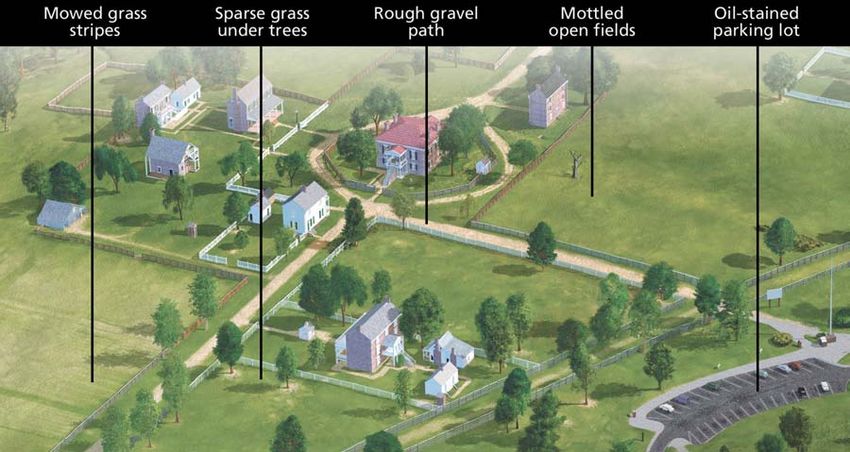
18

from a map in a drawing software application like Adobe Illustrator. Next, you fill the
zones between the contours with gray tones progressing in consistent increments from
dark to light as you go higher. The result is a gray Illustrator file with terraced elevation
zones. Then, the Illustrator file is rasterized in Photoshop and blurred liberally to create a
smooth image with no evidence of the terraces. Finally, you import the blurred grayscale
image into a 3D application and extrude it to represent the terrain surface (Foley, 1997).
The amount of blurring applied is key to success. With too much blurring, the terrain
looks overly smooth and generalized, and with too little blurring, more details become
visible, including the unwanted terraced edges. Complicating matters is the fact that
widely spaced elevation zones require more blurring to appear smooth than do tightly
spaced zones. Producing optimal landscape surfaces depends on trial and error. The view
of Marsh-Billings-Rockefeller National Historical Park, Vermont, uses a primitive DEM
created with this method (figure 5, middle).

I will finish this section by stating the need for an inexpensive and easy-to-use
application for making DEMs from contour lines saved in Adobe Illustrator format,
which would produce DEMs of higher quality than the technique discussed above.

Landscape textures

DEMs look better when they are not bare. At large scales even the most detailed DEM
rendered in a 3D application without any textural covering looks artificial, like molten
plastic. An aerial photograph precisely registered to the DEM and draped onto its surface
goes a long way toward making the final rendered terrain look more presentable. At other
times, such as when aerial photographs are too noisy or have dark and conflicting
shadows, custom-made textures comprised of colors and embossed textures, known as
bump maps, are the better solution. Custom-made textures can derive from multiple
sources, often used in combination with one another, including rasterized vector art,
fractal textures generated in Photoshop and other graphical applications, hand painting in
Photoshop with a Wacom stylus and tablet, and photographs of all kinds. To produce a
grassland texture for the bird’s-eye view of Fort Larned, Kansas, NPS contractor Don
Foley shot a digital photograph of his front lawn from an upstairs window. He then tiled
this small photograph as a larger seamless texture and draped it on the DEM.

The following will help you make effective landscape textures:

• Avoid flat unvarying textures at all costs even if the landscape you are portraying is that
way. Subtle modulations in light and shadow bring a level of realism and visual interest
to even the most boring features. For example, the bird’s-eye view of Appomattox Court
House, Virginia, is comprised largely of empty fields. Instead of representing these areas
with flat green Chris Casady created an image texture that emphasized subtle natural
variations in tone (figure 13).

• Do not over apply landscape textures so that they become noisy and distract from more
important information in the bird’s-eye view. Be especially careful when applying bump
mapping, which can easily become too dark and contrasting.
19

• Readers can’t help but take notice of overly symmetrical, geometric, and repetitive
textures, especially in natural areas. Use them sparingly.

• Clean bright colors may look fine on a traditional map but they are less applicable to
realistic bird’s-eye views. Instead select a color palette comprised of the slightly impure
colors typically found in nature and, if possible, refer to photographs of the site for
greater accuracy. And if most park visitation occurs at a certain time of the year, say, late
summer, the selected colors should reflect that season.

Figure 13. Custom landscape textures bring subtle realism to the bird’s-eye view of Appomattox Court
House, Virginia. Art by Chris Casady.

Buildings—assembly required

Like their brick and mortar counterparts, buildings in a bird’s-eye view take a long time
to construct. The meticulous modeling of small but important architectural details—
eaves, gables, porticos, and the like—accounts for the slow pace. Given the unavoidable
detail, this section looks at how to create building models as efficiently as possible.

Generalization is a logical place to start. Depending on the scale of the scene and its
purpose, not every architectural detail deserves portrayal, thereby saving valuable
production time. One must evaluate all components of a building for what it is they
contribute to our visual understanding of the building in a bird’s-eye view. For example,
does including the rain gutters and downspouts better allow readers to identify a
building? Image resolution is also a factor when generalizing buildings. On buildings that
will appear at thumbnail size, why go to the trouble of modeling the dozens of sub-pixel-
sized porch railings that are below the threshold of visibility? Because only two sides of
20

buildings (plus the roof) are visible in any given view, a simple way to decrease modeling
time is to keep the obscured backsides of buildings blank, much like a movie set. To do
this you must be completely decided about the viewing direction and have no plans to use
the buildings for a virtual reality scene that will be viewable from every which way. The
NPS used this method to decrease costs on the bird’s-eye view of Eisenhower National
Historic Site (figure 25).

The options for generalizing buildings range from simple 2D footprints all the way to
complex 3D models with realistic textures (figure 14). Like the stylized recreational
symbols (camping, hiking etc.) used on NPS visitor-use maps, a building can be distilled
to a much simpler 3D form and still be recognizable to readers. The problem is that,
being the primary information on a bird’s-eye view, buildings demand detailed depiction.
The detail attracts a reader’s eye and subconsciously informs them that these are indeed
places worthy of attention, more so than, say, the parking lot. Sometimes it makes design
sense to show both detailed and generalized buildings in the same scene. For example, for
a park site within an urban setting, depicting the park buildings with more detail than
non-park buildings focuses the reader’s attention on the park. This also spares you hours
of unnecessary labor.

Figure 14. Starting with a simple footprint (1), building depiction becomes more realistic with each
successive image. The most critical steps are going from a blocky “prismatic” model (3) to a model with
angled roofs and flat-shaded detail (5). Building model by Chris Casady.

The NPS is continually on the lookout for new software to more easily produce models.
Photogrammetric modeling software is one of the intriguing methods that we have tried
(we have tested Canoma 1.0, now discontinued, and ImageModeler 4.0). With this
software, which uses oblique aerial or terrestrial photographs of buildings as a guide, the
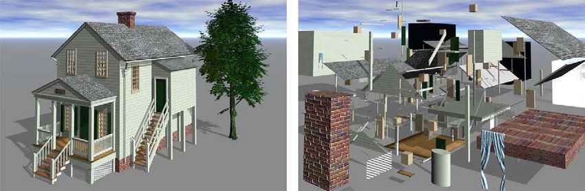
21

user carefully constructs 3D wireframe models over the building shapes seen in the
photographs below. Identifying common points on a building on multiple photographs
increases the accuracy of the resulting 3D model. When the model is complete the
software then “maps” the photographic textures to the surfaces of the building providing
realistic detail (figure 15).

Figure 15. Canoma 1.0 software uses photogrammetric methods to create 3D models from oblique aerial
and terrestrial photographs.

Photogrammetric modeling software is widely used in the related field of urban
simulation to model entire cities. When used in conjunction with LIDAR DEMs (to
determine heights), rectified aerial photographs (to determine locations), terrestrial video
(to obtain facade detail), and semi-automated procedures (to reduce production time), this
software can model thousands of buildings. These are big-budget productions for big-
time cities—London, New York, and Tokyo are among the notable projects (Shiode,
2001). The best-known urban simulation is perhaps Virtual Los Angeles, created by the
Urban Simulation Team, University of California at Los Angeles. They have modeled
large swaths of Los Angeles in sections (see references for URL).

At the NPS, photogrammetric modeling applications have not proven to be the panacea
that we had hoped for. Considering the small size of park sites, which provide little
economy of scale, creating building models with these applications has offered no time
savings. The dense tree growth often found next to buildings in parks also presents
problems. Without unobstructed photographs of buildings from the proper angles,
photogrammetric modeling is next to impossible to use. Finally, there is the highly
subjective matter of aesthetics. Buildings created with photogrammetric modeling
software tend to look like computer simulations rather than the artistic renderings desired
by the NPS

The most detailed and artistic building models produced by the NPS so far have come
from the least sophisticated and most time-consuming techniques. Analogous to the
“stick built” techniques used in real-world construction, this method of modeling
involves assembling sometimes hundreds of 3D objects of various sizes and shapes piece
by piece (figure 16). Building footprints draped on a DEM serve as a guide for
positioning and sizing the assembled buildings in the 3D scene. Borrowing a technique
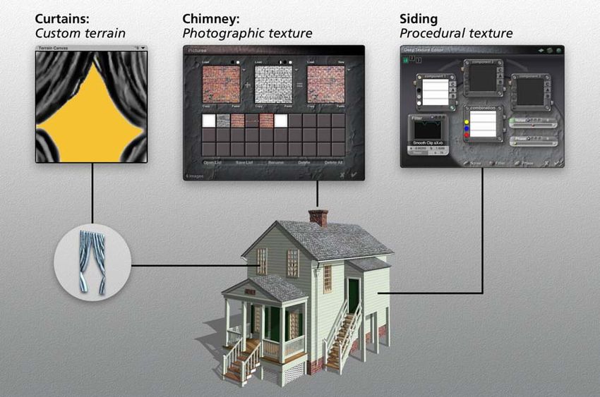
22

from the 19th-century city panoramists, we use digital photographs taken of the buildings
from the ground as an indispensable reference for filling in details on the facades. When
imported into 3D software, the photographs also serve as templates for gauging the
relative sizes of buildings. Strict accuracy, however, is not the intent; our aim is to create
buildings that look realistic and recognizable to readers. In fact, the NPS occasionally
exaggerates the size of the buildings in scenes to improve legibility. For example, at park
sites where the buildings are scattered across expansive tracts of land, at true scale they
are barely noticeable. Exaggerating the size of the buildings—the smaller the scale, the
more exaggeration needed—helps to focus the readers’ attention on them.

Figure 16. (left) Meeks Store is one of 55 buildings, scores of trees, and perhaps a mile of fence found in
the bird’s-eye view of Appomattox Court House National Historical Park, Virginia. (right) The exploded
view of Meeks Store reveals that it is comprised of 308 separate objects. Building model by Chris Casady.

The depiction of buildings involves more than modeling their forms. Exterior textures are
essential for bringing believable realism to buildings, transforming even the most sterile
3D forms into an organic entity. With 3D software, applying exterior textures—shingles,
bricks, stonework, reflective glass, etc.—is often as easy as clicking a mouse in the
libraries of preset textures that come with most 3D applications. If the right texture is not
available in a library, you can create custom textures from photographs and by other
means (figure 17). You many need to accentuate fine textures to make them noticeable
depending on the size and resolution of the depicted building. Bump mapping, a type of
3D embossment, when used in moderation, is an essential technique for giving textures a
more realistic look.
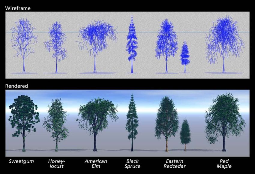
23

Figure 17. The custom textures applied to a model of Meeks Store. Building model by Chris Casady.

Recently the NPS has found a simpler, cheaper, and faster way to model 3D buildings in
Sketchup 5.0, an architectural application that offers user-friendly tools for rapidly
creating 3D buildings. We learned more about the benefits of Sketchup from NPS
contractor, Steven Patricia, an accomplished water colorist who is also a registered
architect. Says Patricia of bird’s-eye views “an artist has to make choices about what is to
be truth and what is to be distortion.” To depict buildings “truthfully” he uses wireframe
models created in Sketchup as a visual reference for painting traditional art. Building
models made in Sketchup are also applicable for an entirely digital workflow. The
models are exportable in common 3D formats (3DS Studio, AutoCAD DXF, and
VRML), complete with attached image textures. File sizes are small, which is an
important consideration when working on projects with many buildings. In a 3D
rendering application like Bryce, the textures on imported Sketchup models are editable,
and realistic bump mapping is easily applied. The NPS has great hopes for Sketchup and
intends to use it for the next appropriate project that comes along.

Trees

Like props on a stage, trees in bird’s-eye views play a secondary role and should be
treated accordingly. When designing a view you soon discover that trees are more
abundant than you ever imagined and grow where you least want them, typically in front
of the most important buildings, hiding their distinctive facades. There are several options
for managing this arboreal profusion: delete, shrink, move, or prune the trees. Visitors to
You can also read