LORAWAN BATTERY-FREE WIRELESS SENSORS NETWORK DESIGNED FOR STRUCTURAL HEALTH MONITORING IN THE CONSTRUCTION DOMAIN - MDPI
←
→
Page content transcription
If your browser does not render page correctly, please read the page content below
sensors
Article
LoRaWAN Battery-Free Wireless Sensors Network
Designed for Structural Health Monitoring in the
Construction Domain
Gaël Loubet 1, * , Alexandru Takacs 1 , Ethan Gardner 2 , Andrea De Luca 2 , Florin Udrea 2 and
Daniela Dragomirescu 1
 1    LAAS-CNRS, Université de Toulouse, CNRS, INSA, UPS, 31400 Toulouse, France;
      alexandru.takacs@laas.fr (A.T.); daniela.dragomirescu@laas.fr (D.D.)
 2    Department of Engineering, University of Cambridge, Cambridge CB3 0FF, UK; elwg2@cam.ac.uk (E.G.);
      ad597@cam.ac.uk (A.D.L.); fu10000@cam.ac.uk (F.U.)
 *    Correspondence: gael.loubet@laas.fr

 Received: 25 January 2019; Accepted: 21 March 2019; Published: 28 March 2019

 Abstract: This paper addresses the practical implementation of a wireless sensors network designed
 to actualize cyber-physical systems that are dedicated to structural health monitoring applications in
 the construction domain. This network consists of a mesh grid composed of LoRaWAN battery-free
 wireless sensing nodes that collect physical data and communicating nodes that interface the
 sensing nodes with the digital world through the Internet. Two prototypes of sensing nodes were
 manufactured and are powered wirelessly by using a far-field wireless power transmission technique
 and only one dedicated RF energy source operating in the ISM 868 MHz frequency band. These
 sensing nodes can simultaneously perform temperature and relative humidity measurements and can
 transmit the measured data wirelessly over long-range distances by using the LoRa technology and
 the LoRaWAN protocol. Experimental results for a simplified network confirm that the periodicity of
 the measurements and data transmission of the sensing nodes can be controlled by the dedicated
 RF source (embedded in or just controlled by the associated communicating node), by tuning the
 radiated power density of the RF waves, and without any modification of the software or the
 hardware implemented in the sensing nodes.

 Keywords: wireless power transmission (WPT); wireless sensor network (WSN); simultaneous
 wireless information and power transfer (SWIPT); cyber-physical systems (CPS); structural health
 monitoring (SHM); Internet of Things (IoT); communicating material

1. Introduction
     By using Internet of Things (IoT) technologies that are now widely available, cyber-physical
systems (CPS) can be implemented to respond to the needs of various applications. In the heart of these
applications lies structural health monitoring (SHM) [1] for buildings, and civil and transportation
infrastructures (e.g., railway and subway stations, bridges, highways, etc.) [2,3], which are part
of the Smart City concepts and paradigms. In parallel, the building information modelling (BIM)
concept [4] has provided new tools to more efficiently plan, design, construct and manage buildings
and infrastructures during the different stages of their lifecycle. At the border between these
concepts (SHM and BIM) the idea of ‘communicating material’ has arisen [5]. A ‘communicating
material’ is intrinsically able to generate, process, store and exchange data from its environment to
dedicated digital systems as a virtual model. A few works have already proposed implementations
of communicating materials based on radio frequency identification (RFID) technology for various

Sensors 2019, 19, 1510; doi:10.3390/s19071510                                   www.mdpi.com/journal/sensors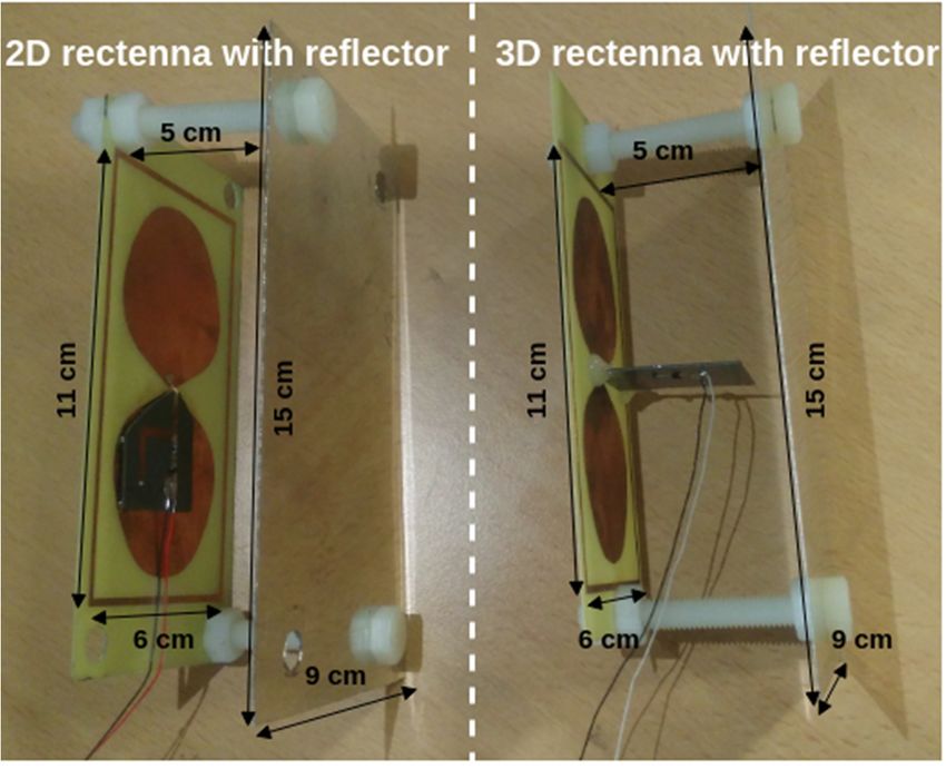
Sensors2019,
Sensors 19,x1510
2019,19, FOR PEER REVIEW 2 2ofof26
26
Sensors 2019, 19, x FOR PEER REVIEW 2 of 26
materials and applications. The main targeted application is the storage and access, at short ranges,
materials
materials and and applications.
applications.The Themain maintargeted
targetedapplication
applicationisisthe thestorage
storageand andaccess,
access,at atshort
shortranges,
ranges,
of some disseminated or measured data in a material like wood [6], textile [7], or concrete [8].
of
of some
some disseminated
disseminated or
or measured
measured data
data in
in aa material like wood [6], textile [7], or concrete [8].
The research project McBIM [9]—communicating material at the disposal of the building
The
The research
research project
project McBIM
McBIM [9]—communicating
[9]—communicating material
materialofat the
atthe disposal
theconcept
disposal of
of the
the building
building
information modelling—aims to provide a practical application of communicating
information
information modelling—aims
modelling—aims to
to provide
provide aa practical
practical application
application of
of the
the concept
concept of
of communicating
communicating
material in the construction domain through communicating reinforced precast concrete. Currently,
material
material in the
the construction
inconcrete construction domain
domain through
through communicating
communicating reinforced
reinforced precast concrete. Currently,
reinforced is the most common construction material thanks to itsprecast concrete.
scalability, Currently,
durability and
reinforced
reinforced concrete
concrete is the most common
is the mostconcrete common construction
construction material
material thanksthanks to its scalability,
to its scalability,durability and
durability
cost [10]. The communicating must be intrinsically able to generate, process, store and
cost [10]. [10].
and cost The communicating concrete must be be
intrinsically able totogenerate, process, store and
exchange data The overcommunicating
several meters from concrete must
its environment intrinsically able
(i.e., the reinforced generate,
precastprocess,
concretestore and
element
exchange
exchange data over several meters from its environment (i.e., the reinforced precast concrete element
that is the data over several
monitored meters
structure) to from its environment
dedicated systems. These (i.e., the reinforced
dedicated precast
systems may concrete
include element
other
that
that is
is the
the monitored
monitored structure)
structure) to
to dedicated
dedicated systems.
systems. These
These dedicated
dedicated systems
systems may
may include
include other
other
structural elements made of communicating concrete (e.g., a floor or a wall) and a unique virtual
structural
structural elements
elements made
made of
of communicating
communicating concrete
concrete (e.g.,
(e.g., aa floor
floor oror aa wall)
wall) and
and aa unique
unique virtual
virtual
model (a BIM), shared or transmitted between all the stakeholders. The system must be functional
model
model (a
(a BIM),
BIM), shared or
shared ortransmitted
transmittedbetween betweenallallthe thestakeholders.
stakeholders. The system must be functional
for the entire lifespan of the element (i.e., several decades) as part ofThe system
a global must
structure beand
functional for
by itself.
for
thethe entire
entire lifespan
lifespan of of the
the element
element (i.e.,
(i.e., several
several decades)
decades) as as part
part of a ofglobal
a global structure
structure and and
by by itself.
itself.
As presented in Figure 1, the properties of precast concrete elements change regularly during
As
As presented
presented in Figure
in Figure 1,1,the theproperties
propertiesofofprecast precast concrete
concrete elements
elements change
change regularly during
regularly
the construction process of a structure, but often virtual/digital information is not shared during
or can the
be
the construction
construction process
process of
of acannota structure,
structure, but often virtual/digital information is not shared or can be
lost. Thus, a new owner havebut often virtual/digital
a complete view of the information
history of their is not shared or
structural can
elements.be lost.
By
lost.
Thus,Thus,
a anew a new
owner owner
cannot cannot
have havea(BIM) a complete
complete view
viewelement,
of the of the history
history of their ofstructural
their structural
elements. elements. By
By joining
joining unique virtual model at each it becomes possible to conserve the entire
joining
a unique a unique virtual model (BIM) at each element, it becomes possible to conserve the entire
history ofvirtual
an element modeland (BIM) at eacha element,
to create virtual model it becomes possible to
of a structure and conserve
each ofthe itsentire history of
components. an
The
history
element ofandan toelement
create aand to create
virtual model aofvirtual
a modeland
structure of each
a structure
of its and each ofThe
components. its components.
virtual model The
can
virtual model can also be updated at each modification (e.g., for each step in the lifecycle, for each
virtual model
also bechange,
updated canatalso bemodification
updated at (e.g., each modification step (e.g.,thefor each step for in theowner
lifecycle, for each
owner etc.) each
and be partially stored in fortheeach
element initself. lifecycle, each change, etc.)
owner change, etc.) and be partially
and be partially stored in the element itself. stored in the element itself.
Changesofofowner
Figure1.1.Changes
Figure ownerfor
fora aprecast
precastconcrete
concreteelement
elementduring
during the
the construction
construction phase of a building.
building.
Figure 1. Changes of owner for a precast concrete element during the construction phase of a building.
As
As presented
presented in Figure2, 2, the
riskrisk of losing information is increased by that
the fact that many
As presentedininFigure
Figure the
2, the of losing
risk information
of losing is increased
information by the fact
is increased by the many industries
fact that many
industries work
work together together on a project and have similar tasks, but do not follow the same methods or
industries workon a project
together on and have and
a project similar
havetasks, buttasks,
similar do not
butfollow
do notthe samethe
follow methods or process
same methods or
process monitoring
monitoring conventions.
conventions.
process monitoring conventions.
Representationof
Figure2.2.Representation
Figure ofthe
theinteractions
interactionsbetween
betweenthe
thestakeholders
stakeholdersworking
workingon
onthe
thedifferent
differenttasks
tasks
Figure
for a 2. Representation
common building of the interactions between the stakeholders working on the different tasks
project.
for a common building project.
for a common building project.
Sensors 2019, 19, x; doi: FOR PEER REVIEW www.mdpi.com/journal/sensors
Sensors 2019, 19, x; doi: FOR PEER REVIEW www.mdpi.com/journal/sensors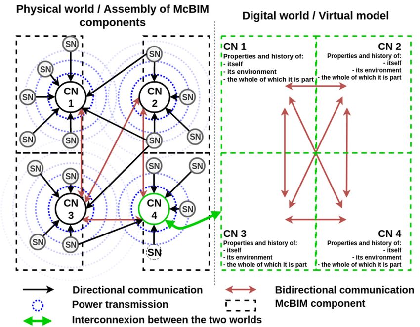
Sensors 2019, 19, 1510                                                                               3 of 26

       Concerning the McBIM project, three main stages of the life cycle of a precast concrete element
are targeted: (i) the manufacture and storage of each element; (ii) the construction of a structure by
the combining of elements; and (iii) the exploitation of the structure, particularly through structural
health monitoring. For instance, the monitoring of the curing process of a fluid screed or a precast
element in terms of temperature and humidity could be a relevant use of communicating concrete
during the manufacturing stage to help with the decision to continue the works (e.g., to unmould, to
tile, etc.). The storage of environmental information of the element within itself and in the BIM allows
the creation of a precise and real-time plan of a structure during the construction phase, whilst also
continuously sharing information between all the stakeholders and track elements. The monitoring of
the temperature at each side of a wall could be relevant during the exploitation phase to quantify the
real thermal resistance of this wall and to certify some standards. Other uses, such as investigating
maturity or applying preventative treatment through the detection of cracks, are also relevant in the
construction domain. Thus, with a unique WSN several different applications can be met during the
entire lifespan of the element according to the use of specific sensors.
       Finally, literature that provides solutions for some specific applications with concrete is outlined.
In [8] a solution based on RFID technology is proposed for monitoring moisture and temperature into
concrete. The communication is short-range (centimetres) and the system only works when deployed
and monitored by a user. This solution requires human interactions and therefore answers only a task
during manufacturing and exploitation stages and cannot be fully automatized. A solution to monitor
mechanical stress—through a load cell—and temperature of a concrete element is provided in [11].
This solution uses a battery which can be charged in the near-field thanks to an inductive wireless
power transfer system and uses the M-BUS wireless protocol to communicate over a few metres.
Again, human interactions are needed, here for the charging process. The tracking of precast concrete
elements is provided in [12,13] by using embedded RFID tags in the concrete elements. In these
cases, no measurement is performed, human interactions are needed for the short range reading,
a smartphone connected to the Internet is required and only the construction phase of a structure
is targeted. Several companies provide solutions to monitor concrete structures. For instance, [14]
proposes a wireless temperature and humidity sensor with a battery based on SigFox (Labège, France)
technology to be embedded into concrete and monitor its curing process for the two cases of in situ
and precast casting. Some sensor nodes using batteries and middle range wireless communication are
provided by [15] to characterize concrete in-situ. Finally, [16] provides an external and generic sensor
to monitor concrete structure. All these solutions have a lifespan estimated at a few years, which is far
less than the lifespan of a reinforced concrete structure.
       In this paper, a smart wireless micro-node mesh network is proposed to design cyber-physical
systems for SHM applications in the construction domain. This is the first step towards designing
fully autonomous communicating concrete. The issues concerning installation and maintenance costs
are considered, as well as the need of having a reliable system for decades. The wireless sensor
network (WSN) presented in Figure 3 is composed of two kinds of nodes: sensing nodes (SNs) and
communicating nodes (CNs).
       The sensing nodes are designed to sense the physical world (i.e., the monitored structure) and
communicate data collected from their environments to the communicating nodes over a distance
ranging from several meters to kilometres. These nodes must be energy autonomous and reliable for
the entire lifespan of the monitored structure because they cannot be accessed once deployed. Thus,
to avoid any maintenance, and for increasing their lifetime, the SNs are designed to be battery-free
and wirelessly powered by a RF source driven by (or even integrated into) the CNs through a far-field
wireless power transmission (WPT) system. As communication and WPT work on the same frequency
band, this architecture answers the paradigm of simultaneous wireless information and power transfer
(SWIPT) [17,18].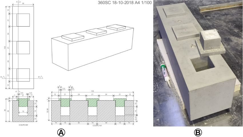
Sensors 2019, 19, 1510 4 of 26
Sensors 2019, 19, x FOR PEER REVIEW 4 of 26
Figure 3.
Figure 3. Schematic
Schematic diagram
diagram of
of the
the architecture
architectureof
ofthe
thewireless
wirelesssmart-nodes
smart-nodesmesh
meshnetwork.
network.
The
Thecommunicating
communicating nodes
nodes are are
designed
designedto aggregate, process,process,
to aggregate, store andstoreexchangeand data
exchangegenerated
data
by the SNs with
generated by the theSNs
other withCNstheand with
other CNstheand
virtual
withmodel through
the virtual the Internet.
model throughAs thethey are accessible,
Internet. As they
they do not need
are accessible, to be
they doenergy
not need autonomous
to be energy for the entire lifetime
autonomous for of
thethe element.
entire Moreover,
lifetime of the the CNs
element.
are able to power the SNs by controlling the RF source dedicated to
Moreover, the CNs are able to power the SNs by controlling the RF source dedicated to the WPT. the WPT.
In
Inthis
thispaper,
paper,an animplementation
implementationof ofaa LoRaWAN
LoRaWANbattery-free
battery-freewireless
wirelesssensing
sensingnode nodeisispresented
presented
and
andcharacterized.
characterized. It It is
is powered
powered via via far-field
far-field WPT
WPT and and measures
measures temperature
temperature and and relative
relativehumidity
humidity
which
which are are then communicated
communicated by by using
using the theLoRa
LoRatechnology
technologyand andthethe LoRaWAN
LoRaWAN protocol
protocol to to
an
an ‘exploded’
‘exploded’ communicating
communicating node node(LoRa(LoRa gateway
gateway andand WPT WPT system
system are are currently
currently separated).
separated). Its
Its periodicity
periodicity of measurement
of measurement andand communication
communication is controlled
is controlled by thebyWPT the system
WPT system through through the
the tuning
tuning
of the of the transmitted
transmitted power.power.Thus, Thus,
as theasneedthe need of measurements
of measurements cannot cannot be fully
be fully specified
specified during
during the
the design
design phase
phase and andcancan change
change during
during thethedifferent
differentphases
phasesofofthe thelifecycle
lifecycle of of the
the element, the the control
control
of
ofthe
theperiodicity
periodicity through
through the WPT
the WPTsystem allows allows
system the hardware and the software
the hardware and thetosoftware
remain unmodified.
to remain
Moreover,
unmodified. some experiments
Moreover, somewere conducted
experiments werewith a networkwith
conducted of two SN prototypes
a network of two of SNsensing
prototypesnodes. of
Although
sensing nodes.our main objective is to provide a communicating reinforced precast concrete, the first
experiments
Although were
our carried out forisgeneric
main objective to provide in-the-air SHM applications
a communicating reinforced and not yet
precast in reinforced
concrete, the first
concrete.
experiments The current objective
were carried outis to
forprovide
generica proof-of-concept of a wirelesslyand
in-the-air SHM applications powered
not yet andinbattery-free
reinforced
wireless
concrete.sensing node designed
The current objective is fortocyber-physical systems dedicated
provide a proof-of-concept to structural
of a wirelessly health and
powered monitoring
battery-
applications
free wirelessinsensing
the construction
node designeddomain. forThis proof-of-concept
cyber-physical systemsmust be powered
dedicated wirelesslyhealth
to structural over
several
monitoringmetres, must senseinsome
applications the relevant
constructionenvironmental
domain. parameters (in this case,must
This proof-of-concept temperature
be powered and
relative humidity, but other types of sensors could be integrated according
wirelessly over several metres, must sense some relevant environmental parameters (in this case, to the targeted application,
such as mechanical
temperature stress humidity,
and relative sensors) and butmust
otherexchange data wirelessly
types of sensors could be(in this caseaccording
integrated for long range,
to the
but some application,
targeted communication suchtechnologies
as mechanical arestress
investigated
sensors)according
and musttoexchange
the targeted dataapplication).
wirelessly (in In the
this
near
case future,
for longthe prototypes
range, but some willcommunication
be embedded into a reinforced
technologies are concrete
investigatedbeamaccording
to experiment
to thewith the
targeted
targeted environment
application). In the near which is a the
future, more difficult medium
prototypes for RF propagation.
will be embedded into a reinforced concrete beam to
Recently,
experiment several
with implementations
the targeted environment of energy
whichautonomous LoRaWAN
is a more difficult medium sensing nodes
for RF dedicated to
propagation.
various applications,
Recently, several essentially for SHM,of
implementations with various
energy software or
autonomous hardware defined
LoRaWAN sensing periodicity,
nodes dedicated from
seconds
to various to applications,
hours, and with various
essentially forkinds
SHM,ofwith sensors,
various such as temperature
software or hardware anddefined
humidity [19,20],
periodicity,
mechanical
from seconds stress [20,21],
to hours, pH [19]
and with variousor electrical currentsuch
kinds of sensors, [22],as have been presented.
temperature and humidity Some are
[19,20],
battery-free
mechanical[20,22,23],
stress [20,21],some harvest
pH [19] ambient energy (e.g.,
or electrical solar[22],
current [19,21,23],
have thermal [19], mechanical
been presented. Some[20], are
inductive
battery-free [22],[20,22,23],
etc.) and otherssome are basedambient
harvest on backscattering
energy (e.g.,[23,24].solar
Some solutions thermal
[19,21,23], that combine [19],
mechanical [20], inductive [22], etc.) and others are based on backscattering [23,24]. Some solutions
that combine multiple sources are proposed, too [19,21,23]. These projects are listed in Table 1.
Sensors 2019, 19, x; doi: FOR PEER REVIEW www.mdpi.com/journal/sensors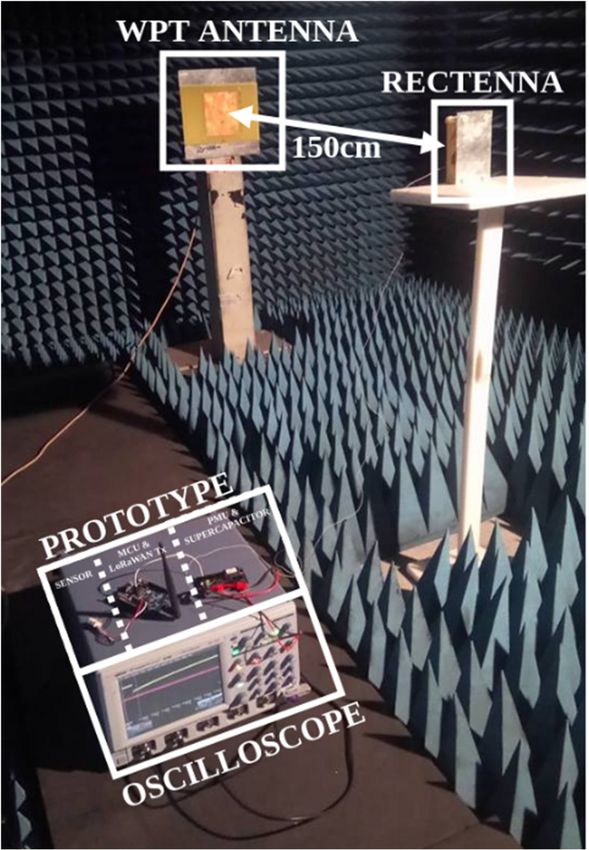
Sensors 2019, 19, 1510                                                                                              5 of 26

multiple sources are proposed, too [19,21,23]. These projects are listed in Table 1. Nevertheless, and
although the feasibility of WPT for powering a LoRaWAN node was demonstrated theoretically in [25],
no complete implementation was provided until [26]. The advantage of WPT over ambient energy
harvesting is that it is not dependent on the availability of the fluctuating ambient sources. Some
estimates of available harvestable energy in buildings are shown in [27].

      Table 1. Comparative study of implementations of LoRaWAN sensing nodes supplied by an
      energy-harvesting system.

                                        Energy                            Periodicity of
   [Reference]            Energy
                                        Storage       Sensor Type       Measurement and/or          Application(s)
      Year               Source(s)
                                      Capacitance                         Transmission
                                                      Temperature
       [20]          Mechanical
                                        100 mF       Humidity (rain)    3 h 30 min (estimation)      Bridges SHM
       2016          (vibrations)
                                                     Vehicles counter
                                                                                                    SHM; Precision
                                                                                                   agriculture; Smart
       [24]                                                                                           contact lens;
                    Backscattering       N/A              N/A                   N/A
       2017                                                                                             Flexible
                                                                                                    epidermal patch
                                                                                                         sensor
                                                        Electricity
       [22]              Electrical
                                         22 mF       consumption/AC         Seconds (few)             Smart grids
       2018              induction
                                                         current
       [21]              Solar and    2 F and 1400                                                SHM of construction
                                                       Crackmeter               N/A
       2018               battery         mAh                                                         materials
                                                      Temperature
       [19]              Solar and                                                                environment (water)
                                         20 Ah         Humidity                 Hour
       2018               thermal                                                                     monitoring
                                                         pH
       [23]         Backscattering
                                         33 mF            N/A            20 min (estimation)             N/A
       2018           and solar
                                                                                                    Communicating
                                                                        Controlled by the WPT
                                                      Temperature                                      material
    This work                                                                   system
                         RF WPT          22 mF          Relative                                     SHM in harsh
      2019                                                               (minutes to hours, or
                                                       humidity                                      environments
                                                                                 more)
                                                                                                          CPS

     A complete specification of the implemented prototype of the sensing node will be the core of
Section 2. Section 3 will highlight the obtained experimental results for a SN prototype and for a
network of two prototypes of sensing nodes over the air. Discussions and future improvements will be
discussed in Section 4.

2. Design and Implementation of the Prototype of Sensing Nodes
     Due to its need for complete energy autonomy, the design of the sensing node is more challenging
than the design of the communicating nodes. As previously described, the SNs must be battery-free
and wirelessly powered, generate data by sensing their environment and transmitting these data
wirelessly to the CNs.

2.1. Topology of the Sensing Nodes
     Figure 4 shows the architecture chosen for the sensing node prototype. The SNs use a temperature
and relative humidity sensor to sense their environment, which will be, in the end, reinforced precast
concrete elements. The collected data are recorded by a microcontroler unit (MCU) in a LoRaWAN
frame to be transmitted to the CNs through a wireless unidirectional radiofrequency communication
based on LoRa technology. In order to help achieve energy autonomy, the SNs must be low power and
as simple as possible. Therefore, they must carry out minimal data processing and should not store the
collected data once transmitted. To provide the energy autonomy for decades without access, the SNs
are battery-free and wirelessly powered through a far-field RF WPT system, which is controlled by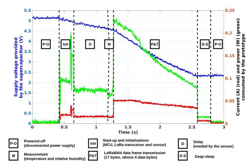
Sensors 2019, 19, x FOR PEER REVIEW 6 of 26
communication based on LoRa technology. In order to help achieve energy autonomy, the SNs must
be low power and as simple as possible. Therefore, they must carry out minimal data processing and
should2019,
Sensors not19,store
1510 the collected data once transmitted. To provide the energy autonomy for decades 6 of 26
without access, the SNs are battery-free and wirelessly powered through a far-field RF WPT system,
which is controlled by the CNs. A rectenna is used in the SNs to harvest the dedicated generated RF
the
powerCNs. A rectenna
density is used initthe
and transform SNs
into DCtopower
harvestwhich
the dedicated generated
is supplied RF power
to a power density unit
management and
transform it into DC power which is supplied to a power management unit (PMU).
(PMU). This PMU has the role of efficiently managing the energy provided by the rectenna. It needs This PMU has
the role of
to store thisefficiently
energy inmanaging the energy
a supercapacitor andprovided by the
when there rectenna.
is enough It needs
energy to storeallthis
to power theenergy
active
in a supercapacitor and when there is enough energy to power all the active
components (sensor, MCU and LoRa transceiver), deliver this energy to perform a measurement components (sensor,
and
MCU and LoRa transceiver), deliver this energy to perform a measurement and
a complete wireless transmission. As the SNs are inaccessible once deployed, no software or a complete wireless
transmission. As the SNscan
hardware modifications arebe
inaccessible once deployed,
made. Nevertheless, no software
by controlling the or
RFhardware modifications
power density illuminatingcan
be made. Nevertheless, by controlling the RF power density illuminating the SNs,
the SNs, the activation and periodicity of the measurement and transmission can be managed by the activation and
periodicity
the CNs. of the measurement and transmission can be managed by the CNs.
Figure 4.
Figure Schematic diagram
4. Schematic diagram of
of the
the architecture
architecture of
of the
the battery-free
battery-free wireless
wireless sensing
sensing node.
node.
2.2. Rectennas
2.2. Rectennas
To ensure the energy autonomy of the SNs, different strategies can be employed. As presented
To ensure the energy autonomy of the SNs, different strategies can be employed. As presented
in Table 1, there are some published works on LoRaWAN sensing nodes based on energy harvesting
in Table 1, there are some published works on LoRaWAN sensing nodes based on energy harvesting
techniques. The available energy sources and the best strategies to scavenge them in buildings and
techniques. The available energy sources and the best strategies to scavenge them in buildings and
for SHM applications are highlighted in [27]. Unfortunately, these sources are too low, too fluctuating
for SHM applications are highlighted in [27]. Unfortunately, these sources are too low, too fluctuating
and sometimes unavailable for our targeted applications. For instance, light sources, air flows and
and sometimes unavailable for our targeted applications. For instance, light sources, air flows and
thermal gradients are not available in concrete. The mechanical sources (e.g., vibrations) are fluctuating
thermal gradients are not available in concrete. The mechanical sources (e.g., vibrations) are
and hardly related to the uses of the structure (e.g., bridge, residential building, etc.). And the RF
fluctuating and hardly related to the uses of the structure (e.g., bridge, residential building, etc.). And
power densities measured in a laboratory in [27] are very low, specifically between 1.69 pW/cm2 in
the RF power densities measured in a laboratory in [27] are very low, specifically between
the 2.45 GHz ISM band and 57.37 nW/cm2 in the 900 MHz GSM band. Finally, the strategy of the RF
1.69 pW/cm² in the 2.45 GHz ISM band and 57.37 nW/cm² in the 900 MHz GSM band. Finally, the
wireless power transmission was chosen because of the complete control of the energy source and the
strategy of the RF wireless power transmission was chosen because of the complete control of the
possibility of managing the activation and periodicity of measurement and data transmission by tuning
energy source and the possibility of managing the activation and periodicity of measurement and
the transmitted power. There are two different approaches for RF WPT: the magnetic or near-field
data transmission by tuning the transmitted power. There are two different approaches for RF WPT:
WPT as presented in [8,28,29] in the case of SHM of reinforced concrete structures applications, and the
the magnetic or near-field WPT as presented in [8,28,29] in the case of SHM of reinforced concrete
far-field RF WPT used in this project. The far-field solution can increase the useful range between the
structures applications, and the far-field RF WPT used in this project. The far-field solution can
RF source and the sensing nodes. This maximum distance is related to the chosen frequency through
increase the useful range between the RF source and the sensing nodes. This maximum distance is
the free space losses and to propagation medium through its dielectric properties. It should be noted
related to the chosen frequency through the free space losses and to propagation medium through its
that the capabilities of the far-field WPT systems are limited today mainly by regulations (i.e., the
dielectric properties. It should be noted that the capabilities of the far-field WPT systems are limited
maximum effective isotropic radiated power (EIRP) that can be radiated in the ISM bands [30]) and
today mainly by regulations (i.e., the maximum effective isotropic radiated power (EIRP) that can be
not by the technology itself. For instance, the maximum EIRP for the ISM 868 MHz frequency band is
radiated in the ISM bands [30]) and not by the technology itself. For instance, the maximum EIRP for
2 W (or +33 dBm).
the ISM 868 MHz frequency band is 2 W (or +33 dBm).
In order to scavenge the generated RF power densities, specially designed rectennas (the acronym
for “rectifying antenna”) are used. They are tuned to operate efficiently around the ISM 868 MHz band.
Sensors 2019, 19, x; doi: FOR PEER REVIEW www.mdpi.com/journal/sensors
The choice of this frequency is justified by a compromise between the free space losses and the size of
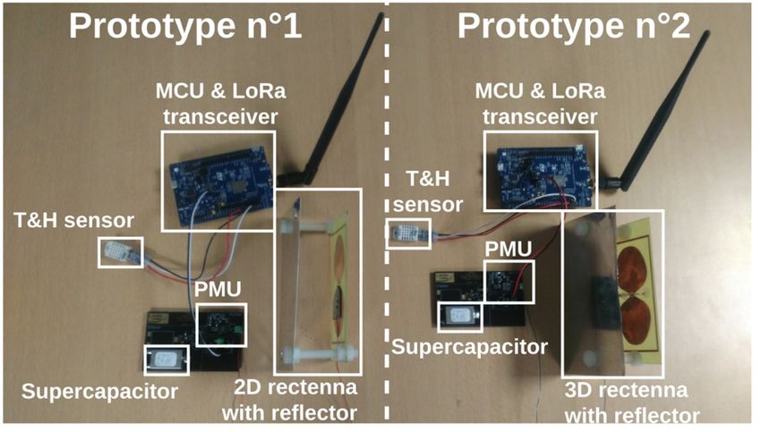
the required antenna. The used rectennas, presented in Figure 5, are composed of: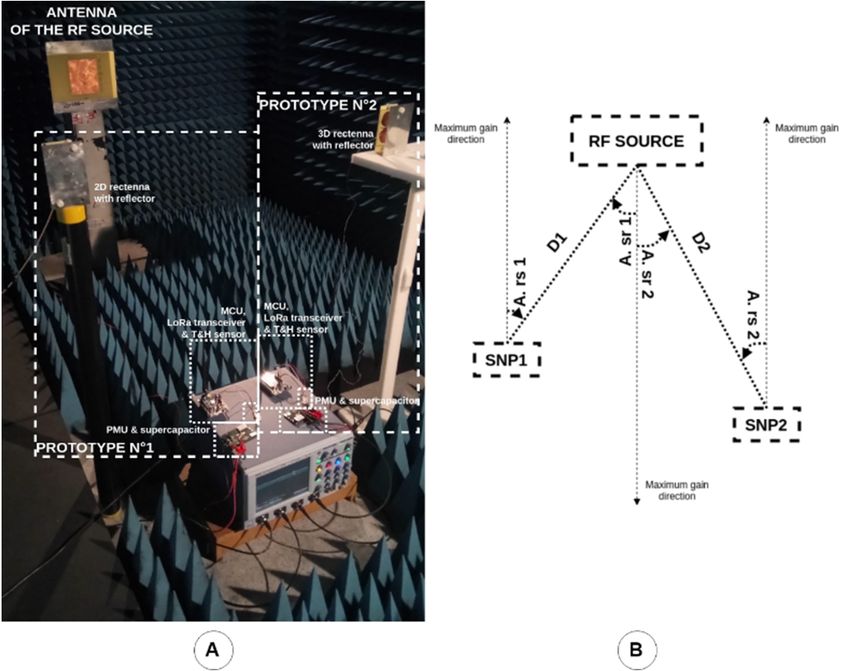
(2D) rectenna. For the second rectenna, the RF rectifier is orthogonally connected with the antenna to
have a three-dimensional (3D) rectenna.
(iii) a metallic reflector (15 cm × 9 cm) positioned at 5 cm behind the rectennas (2D and 3D),
which can increase the antenna gain (respectively from +2.2 dBi to +6.6 dBi) while having a
three-dimensional structure comparable in terms of volume with the three-dimensional rectenna
Sensors 2019, 19, 1510 7 of 26
used in [32]. The manufactured rectennas are represented in Figure 6.
The use of the metallic reflector increases the rectenna performance by improving the directivity
and the gain of the
(i) a compact (11antenna
cm × 6 in cm)theand
opposite direction
broadband of the
dipole reflector.
antenna The adding
enclosed of a metallicring
by a rectangular reflector
[31],
increases the DC power
manufactured on FR4 harvested.
substrate (thickness: 0.8 mm, relative electric permittivity: 4.4 and loss
Undesirable
tangent: 0.02) harmonics are generated
which captures during the
and converts the rectifying
generatedprocess, both at the
electromagnetic input and
energy fieldoutput
into a
portsRF of the diode,
signal which
around theis ISM
a nonlinear
868 MHz component.
band. Its An impedance
simulated matching circuit
(HFSS—High composed
Frequency of a
Structure
bent short-circuited
Simulator—from stub and an
Ansys Inc.inductor of 33 nH
(Canonsburg, PA,isUSA))
inserted before the
maximal gainRFis rectifier
+2.2 dBito atbe a band-pass
this frequency.
filter aand
(ii) to avoid
single the re-radiation
Schottky diode (Broadcom by the Inc.
antenna
(SanofJose,
the generated
CA, USA) harmonics.
HSMS 2850Thus, mountedthe RF in power
series
conversion efficiencyhigh-frequency
configuration) is maximized. Again, a low-pass
RF rectifier filter is inserted
(manufactured after the
on Rogers RF rectifier (Chandler,
Corporation to provide
a DCAZ, signal to the
USA) PMU.
RT/Duroid 5870 substrate, thickness: 0.787 mm, relative electric permittivity: 2.3
The results depicted
and loss tangent: 0.0012) in Figurewhich7 demonstrate
converts the that the manufactured
guided RF signal into rectennas operate
DC power. Forefficiently
the first
for low power densities of the incident RF waves. These generated power
rectenna, the RF rectifier is connected with the antenna in an overlapping manner to have densities are higher than a
thoseplanar
available in buildings [27] and, consequently, a dedicated RF power source
two-dimensional (2D) rectenna. For the second rectenna, the RF rectifier is orthogonally is required. Thus,
DC powers
connectedgreater
withthan 50 µW can
the antenna be harvested
to have if the incident
a three-dimensional power
(3D) density exceeds 0.42 µW/cm²
rectenna.
and 0.50 µW/cm² respectively for the 2D and 3D rectenna.
(iii) a metallic reflector (15 cm × 9 cm) positioned at 5 cm behind the rectennasMoreover, these rectennas (2D are relatively
and 3D),
broadband, covering the ISM 868 MHz and 915 MHz bands, and
which can increase the antenna gain (respectively from +2.2 dBi to +6.6 dBi) whilea part of the GSM 900 MHz bands.
having a
Regarding Figure 7, the 2D rectenna is superior to the 3D rectenna with
three-dimensional structure comparable in terms of volume with the three-dimensional rectenna the use of the metallic
reflector
usedatin868 MHz.
[32]. The Nevertheless,
manufacturedboth designs
rectennas areare within one
represented inorder
Figureof6.magnitude in terms of DC
power. More details concerning the rectennas used in this SN prototype are reported in [33].
Sensors 2019, 19, x FOR PEER
Figure
Figure 5. REVIEW
5. (A) Block
(A) Block diagram
diagram and
and (B)
(B) schematic
schematic of
of the
the manufactured
manufactured rectenna.
rectenna. 8 of 26
Sensors 2019, 19, x; doi: FOR PEER REVIEW www.mdpi.com/journal/sensors
Figure 6. Photograph of the manufactured rectennas.
rectennas.
Sensors 2019, 19, 1510 8 of 26
Sensors 2019, 19, x FOR PEER REVIEW 8 of 26
The use of the metallic reflector increases the rectenna performance by improving the directivity
and the gain of the antenna in the opposite direction of the reflector. The adding of a metallic reflector
increases the DC power harvested.
Undesirable harmonics are generated during the rectifying process, both at the input and output
ports of the diode, which is a nonlinear component. An impedance matching circuit composed of a
bent short-circuited stub and an inductor of 33 nH is inserted before the RF rectifier to be a band-pass
filter and to avoid the re-radiation by the antenna of the generated harmonics. Thus, the RF power
conversion efficiency is maximized. Again, a low-pass filter is inserted after the RF rectifier to provide
a DC signal to the PMU.
The results depicted in Figure 7 demonstrate that the manufactured rectennas operate efficiently
for low power densities of the incident RF waves. These generated power densities are higher than
those available in buildings [27] and, consequently, a dedicated RF power source is required. Thus,
DC powers greater than 50 µW can be harvested if the incident power density exceeds 0.42 µW/cm2
and 0.50 µW/cm2 respectively for the 2D and 3D rectenna. Moreover, these rectennas are relatively
broadband, covering the ISM 868 MHz and 915 MHz bands, and a part of the GSM 900 MHz bands.
Regarding Figure 7, the 2D rectenna is superior to the 3D rectenna with the use of the metallic reflector
at 868 MHz. Nevertheless, both designs are within one order of magnitude in terms of DC power.
More details concerning the rectennas
Figure used inofthis
6. Photograph the SN prototyperectennas.
manufactured are reported in [33].
Figure 7. Measured
Figure 7. rectenna performances:
Measured rectenna performances:(A) (A)DC
DCvoltage
voltageversus
versusfrequency
frequency(load:
(load:1010 kΩ,
kΩ, input
input
power: +0 dBm)
power: dBm) and
and (B)
(B) DC
DC power
powerversus
versusilluminating
illuminatingpower
powerdensities (frequency:
densities (frequency: 868868
MHz,
MHz,load:
load:
10kΩ);
10 kΩ); both
both the 2D-rectenna with
with reflector
reflector (red)
(red)and
andthe
the3D-rectenna
3D-rectennawith
withreflector
reflector(blue).
(blue).
2.3.
2.3. Power
Power Management Unit
Management Unit
To
Toefficiently
efficiently manage
manage and and store
store the
the DC
DCpower
powerprovided
providedby bythe
therectenna,
rectenna,a apower
power management
management
unit
unit (PMU) is used. The Texas Instruments (Dallas, TX, USA) bq25504 [34] is chosen because of of
(PMU) is used. The Texas Instruments (Dallas, TX, USA) bq25504 [34] is chosen because itsits
minimum
minimum required input DC
required input DC power
power (15
(15 µW approximately).This
µW approximately). ThisPMU
PMUalsoalsocontains
contains a DC-to-DC
a DC-to-DC
convertor. Figure 8 shows the PMU operational behaviour. The PMU
convertor. Figure 8 shows the PMU operational behaviour. The PMU must efficiently charge must efficiently charge thethe
supercapacitor with the DC power provided by the rectenna and discharge
supercapacitor with the DC power provided by the rectenna and discharge the supercapacitor tothe supercapacitor to power
all the active
power all thecomponents (the temperature
active components and relative
(the temperature and humidity sensor, the
relative humidity MCUthe
sensor, andMCUthe LoRaWAN
and the
transceiver) when enough
LoRaWAN transceiver) whenstored energy
enough is available.
stored To optimize
energy is available. To its storageitsoperation,
optimize a maximum
storage operation, a
power
maximumpointpower
tracking
point(MPPT) hardware
tracking (MPPT)function
hardware is implemented in the PMU.inRegarding
function is implemented the PMU. its operation,
Regarding
its operation,
the PMU stores thethe
PMU stores the
available available
power untilpower until the
the voltage at voltage
the ports at of
thethe
ports of the supercapacitor
supercapacitor exceeds a
exceeds threshold
selected a selected threshold (Vmax =and
(Vmax = 5.25V) 5.25V)
thenand then supplies
supplies the active the components
active components untilsame
until this this voltage
same
voltage goes down under another selected threshold (V = 2.30V). Moreover,
goes down under another selected threshold (Vmin = 2.30V). Moreover, both over- and under-voltage
min both over- and under-
voltage protections
protections are usedare byused by the When
the PMU. PMU. theWhen the (under-)
(under-) over-voltage
over-voltage threshold
threshold is attained
is attained the
the active
active components
components and theand the supercapacitor
supercapacitor are disconnected
are disconnected in orderintoorder to prevent
prevent a deep (dis)charge.
a deep (dis)charge. The PMU
The PMU aintegrates
integrates cold-starta procedure.
cold-start procedure.
Thus, if aThus, if a minimal
minimal voltage voltage
of around of around
350 mV350 andmV and a
a minimal
Sensors 2019, 19, x; doi: FOR PEER REVIEW www.mdpi.com/journal/sensors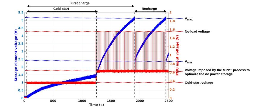
Sensors 2019, 19, 1510 9 of 26
Sensors 2019, 19, x FOR PEER REVIEW 9 of 26
DC power
minimal of 15 µW
DC power areµW
of 15 provided to the to
are provided PMU, it can itbecan
the PMU, self-powered
be self-poweredand begin the storage
and begin of the
the storage
of the input power in the supercapacitor. Once enough energy is stored to reach almost 1.3 V voltage at
input power in the supercapacitor. Once enough energy is stored to reach almost 1.3 V voltage
at the
the ports of the supercapacitor,
supercapacitor, thethePMU
PMUswitches
switcheson oncompletely,
completely,optimizes
optimizesitsitsoperation
operation and
and more
more
efficiently charges the supercapacitor. When
efficiently charges the supercapacitor. When a voltagea voltage higher than 1.3
1.3 V is available at the ports ofthe
V is available at the ports of
supercapacitor, the cold-start procedure is no longer necessary,
the supercapacitor, the cold-start procedure is no longer necessary, even even if there was was
if there no DC noinput power
DC input
provided
power for a long
provided for a period. The PMU
long period. intrinsic
The PMU consumption—announced
intrinsic consumption—announced around 15 µW—is
around limiting
15 µW—is
regarding the minimum power that must be scavenged by the rectenna to allow
limiting regarding the minimum power that must be scavenged by the rectenna to allow the complete the complete charge
of theofsupercapacitor.
charge the supercapacitor.
Figure
Figure 8. 8. Voltage
Voltage waveforms
waveforms at at
thethe ports
ports of of
thethe supercapacitor
supercapacitor (blue)
(blue) and
and rectenna
rectenna output
output voltage
voltage
(red),
(red), forfor a –8
a –8 dBm
dBm RFRF power
power at at
thethe input
input ofof the
the RFRF rectifier.
rectifier.
2.4. Supercapacitor
2.4. Supercapacitor
An AVX Corporation (Greenville, SC, USA) BZ01CA223ZSB supercapacitor [35] of 22 mF of
An AVX Corporation (Greenville, SC, USA) BZ01CA223ZSB supercapacitor [35] of 22 mF of
capacitance (noted as C) is chosen in order to store enough energy to power all the active components
capacitance (noted as C) is chosen in order to store enough energy to power all the active components
during the required time for measurements (temperature and relative humidity) and the LoRaWAN
during the required time for measurements (temperature and relative humidity) and the LoRaWAN
transmission of a data frame. The supercapacitor exhibits a low loss current of 10 µA which must be
transmission of a data frame. The supercapacitor exhibits a low loss current of 10 µA which must be
take into consideration to estimate properly the required power that must be scavenged by the rectenna
take into consideration to estimate properly the required power that must be scavenged by the
to power the PMU and to allow the complete use of the supercapacitor to store energy. The cycles of
rectenna to power the PMU and to allow the complete use of the supercapacitor to store energy. The
charges and discharges are managed by the PMU between Vmax and Vmin voltages. The energy stored
cycles of charges and discharges are managed by the PMU between Vmax and Vmin voltages. The
(noted as E) by the supercapacitor can be estimated as:
energy stored (noted as E) by the supercapacitor can be estimated as:
C 2 2
E== 2∙ · Vmax − Vmin (1)(1)
2
ByBy using
using Equation(1),
Equation (1),the
theenergy
energystored
storedbybythe
the2222 mF
mF supercapacitor
supercapacitor is estimated
estimated toto 245
245mJmJininits
itsvoltage
voltagerange
range(between
(betweenVVmax = 5.25
max = 5.25VVand
andVVmin
min== 2.30
2.30 V).V). Figure
Figure 9 shows
9 shows the
the consumption
consumption ofof
thethe
SNSN
prototype
prototype forfor a complete
a complete operation
operation (measurement
(measurement andand wireless
wireless communication).
communication). ItsIts consumption
consumption is is
estimated at 214 mJ. Thus, enough energy is stored by the PMU in the supercapacitor
estimated at 214 mJ. Thus, enough energy is stored by the PMU in the supercapacitor to power the to power the
sensor,
sensor, the
the MCU
MCU and
and the
the LoRa
LoRa transceiver
transceiver duringa acomplete
during completeoperation.
operation.
Sensors 2019, 19, x; doi: FOR PEER REVIEW www.mdpi.com/journal/sensors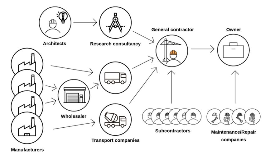
Sensors2019,
Sensors 19,x1510
2019,19, FOR PEER REVIEW 1010ofof26
26
Figure
Figure9.9.Supply
Supplyvoltage
voltage(blue),
(blue),current
currentconsumption
consumption(red),
(red),and
andpower
powerconsumption
consumption(green)
(green)of
ofthe
the
SN
SNprototype.
prototype.
2.5.Microcontroller
2.5. MicrocontrollerUnit
Unitand
andLoRa
LoRaTransceiver
Transceiver
ToTo manage
manage the the temperature
temperature and and relative
relative humidity
humiditysensor,
sensor, to tocapture
capturethe themeasured
measureddata datain inaa
LoRaWAN data frame and to control the LoRa transceiver, a microcontroller
LoRaWAN data frame and to control the LoRa transceiver, a microcontroller unit is used. The LoRa unit is used. The LoRa
frame generated
frame generated by by thethe MCU
MCU is is then
then transmitted
transmitted by by aa LoRa
LoRa transceiver.
transceiver. These These processes
processes are are
accomplished thanks to a Murata Manufacturing Co., Ltd. (Nagaokakyo-shi,
accomplished thanks to a Murata Manufacturing Co., Ltd. (Nagaokakyo-shi, Kyoto Prefecture, Japan) Kyoto Prefecture,
Japan) CMWX1ZZABZ-091
CMWX1ZZABZ-091 all-in-one all-in-one
LoRaWAN LoRaWAN communication
communication modulemodule [36][36] (composedofof aa
(composed
STMicroelectronics(Schiphol,
STMicroelectronics (Schiphol,Amsterdam,
Amsterdam,Netherlands)
Netherlands)STM32L072CZ
STM32L072CZ[37] [37]MCU
MCUbased basedon onan anARM
ARM
Cortex M0+ and a Semtech (Camarillo, CA, USA) LoRa transceiver
Cortex M0+ and a Semtech (Camarillo, CA, USA) LoRa transceiver SX1276 [38]). A B-L072Z- SX1276 [38]). A B-L072Z-LRWAN1
development
LRWAN1 board [39]board
development by STMicroelectronics
[39] by STMicroelectronics(Schiphol, (Schiphol,
Amsterdam, Netherlands)
Amsterdam, including
Netherlands)
the aforementioned hardware was chosen. As stated, the transceiver
including the aforementioned hardware was chosen. As stated, the transceiver manages the manages the LoRa physical
LoRa
layer protocol, whereas the MCU manages the sensor, the
physical layer protocol, whereas the MCU manages the sensor, the LoRaWAN protocol stack andLoRaWAN protocol stack and the the
applicationsoftware.
application software.
As presented
As presented in inFigure
Figure9,9,onceoncepowered,
powered,the theMCUMCUswitches-on
switches-onand andinitializes
initializesitselfitselfand
andall allthe
the
other active components (the temperature and relative humidity sensor
other active components (the temperature and relative humidity sensor and the LoRa transceiver) and the LoRa transceiver) (‘Init’
and ‘D’
(‘Init’ stages).
and Then it manages
‘D’ stages). Then it the measurement
manages from the sensor
the measurement from(providing
the sensortwo measurements
(providing two
encoded on two bytes) (‘M’ stage), processes the data and creates
measurements encoded on two bytes) (‘M’ stage), processes the data and creates a LoRaWAN a LoRaWAN frame (17 bytes long,
frame
whose
(17 bytes 13 long,
bytes whose
are induced13 bytes by theare LoRaWAN
induced byprotocol)
the LoRaWANand drives the LoRa
protocol) andtransceiver
drives thetoLoRa send
the LoRaWAN data frame (17 bytes long) (‘P and T’ stage). Once
transceiver to send the LoRaWAN data frame (17 bytes long) (‘P and T’ stage). Once the complete the complete data frame is sent,
the system goes into a deep-sleep mode (‘D–S’ stage). All these operations
data frame is sent, the system goes into a deep-sleep mode (‘D–S’ stage). All these operations are are performed each time
the SN prototype
performed each time is supplied and the entire
the SN prototype loop lasts
is supplied andnearly 2.13 s.loop
the entire The lasts
largest amount
nearly 2.13ofs. DC
Thepower
largestis
required by the LoRa transceiver during the transmission of the LoRaWAN
amount of DC power is required by the LoRa transceiver during the transmission of the LoRaWAN data frame. Nevertheless,
for our
data frame.applications,
Nevertheless, the for
measurements
our applications, and thethewireless communication
measurements must not
and the wireless be performed
communication
continuously
must (e.g., the temperature
not be performed continuously and thethe
(e.g., humidity shouldand
temperature be measured
the humidity and transmitted
should be measured hourly or
once a day/week, etc.). The transmission respects LoRaWAN class
and transmitted hourly or once a day/week, etc.). The transmission respects LoRaWAN class A A standard (the node transmits
data but (the
standard cannot
node betransmits
interrogated),
data but with a +2 be
cannot dBm radio frequency
interrogated), with aoutput
+2 dBmpower at 868 MHz
radio frequency (ISM
output
power at 868 MHz (ISM band), an activation by personalization (ABP) and without causing the
band), an activation by personalization (ABP) and without causing an acknowledgment from an
network. This allfrom
acknowledgment aids tothelimit the number
network. This allofaids
exchanges
to limitandthe reduce
numberthe of global
exchanges power and consumption.
reduce the
The bandwidth
global is 125 kHz and
power consumption. Thethe spreading
bandwidth is factor
125 kHz is 12,
and allowing a data-rate
the spreading factor ofis293
12,bps. It is probable
allowing a data-
that this configuration can be further optimized to consume less energy.
rate of 293 bps. It is probable that this configuration can be further optimized to consume less energy.
Forthe
For thetargeted
targetedapplication,
application,the thecommunication
communicationbetween betweenSNs SNsand andCNsCNsmustmustbe bewireless
wirelessand and
unidirectional(only
unidirectional (onlyuplink)
uplink)in inorder
orderto toreduce
reducethe theDC DCconsumption
consumptionby bydeleting
deletingthe theactive
activereception
reception
process. The targeted distance between SN and CN is in the range of tens of metres (middle range)
Sensors 2019, 19, x; doi: FOR PEER REVIEW www.mdpi.com/journal/sensorsSensors 2019, 19, 1510 11 of 26
process. The targeted distance between SN and CN is in the range of tens of metres (middle range) or
kilometres (long range). LoRa technology and the LoRaWAN protocol are chosen for implementing
our SN prototype because of: (i) the intrinsic long-range capabilities and (ii) the availability of a reliable
infrastructure in the laboratory. Thus, a long-range (1.3 km) wireless communication between the SN
prototype (located at LAAS-CNRS Toulouse, France, GPS coordinates: 43◦ 330 45.300 N 1◦ 280 38.400 E)
and a LoRa gateway (installed on the INSA campus Toulouse, France, GPS coordinates: 43◦ 340 14.800 N
1◦ 270 58.500 E) can be performed. The data measured and transmitted by the SN are then routed by the
TheThingsNetwork [40] network, up to servers, where these can be recovered and processed to obtain
a complete cyber-physical system.
However, the choices of LoRa technology and the LoRaWAN protocol are not necessarily the
best regarding the targeted application. Table 2 shows a short comparison between three technologies
(LoRaWAN, Bluetooth Low Energy (BLE) and RuBee) identified as possible solutions to implement the
wireless communication between the SNs and the CNs for different communication ranges (long and
middle). It should be noted that the RuBee technology that is based on near-field communication, is not
yet commercially available. It defines intrinsically an auxiliary channel for the WPT and is defined as
insensitive to reinforced concrete and water. Conversely, BLE used the ISM 2.45 GHz band which is
very sensitive to water and thus to concrete. Finally, LoRa is the most consuming solution among the
three presented but with, in return, the longest reach. To estimate properly the power consumption of
each standard, a hardware module must be selected and the duration of data communication (only
uplink or bidirectional as function of the selected standard and/or application) must be considered.
Table 2. Comparative study of three wireless communication technologies identified as possible
solutions for the wireless communication between the SNs and the CNs.
Minimal Data
Frequency Band
Technology Standard Directionality Range Frame Size
(ISM)
(byte)
Uplink
LoRaWAN 433/868/915 MHz Long
LoRa (Downlink 14
[41] (far-field) (km)
restricted)
Bluetooth Low Bidirectional
IEEE 802.15.1 2.4 GHz Middle
Energy “Uplink-only” 11
[42] (far-field) (tens of m)
(BLE) available
131 kHz
IEEE 1902.1 Middle
RuBee Bidirectional (near-field) 5
[43] (tens of m)
(65 kHz for WPT)
2.6. Temperature and Relative Humidity Sensor
To measure the temperature and relative humidity, an Adafruit Industries (New York City, NY;
USA) DHT22 [44] active sensor is used. Each measurement is coded on 2 bytes and has a resolution
respectively of 0.1 ◦ C and 0.1%. The measured average consumption of this sensor for its initialization
and a unique measurement is 30 mW for a voltage varying from Vmax to Vmin or, in other words, nearly
64 µJ are needed to initialize and use this sensor for temperature and relative humidity measurements.
This represents nearly 30% of the consumed energy and 26% of the stored and available energy. This
sensor needs a ‘stabilized’ supply voltage between 3 V and 5 V during at least one second before
performing its first measurement. Additionally, two seconds are needed between two consecutive
measurements. The communication with the MCU is assured by a one-wire homemade protocol. Thus,
this active sensor is not low-power, rather slow and is selected mainly by its availability and ease of
use, with the objective to have a complete proof of concept. In addition, it is not dedicated to harsh
environment and could not be embedded in concrete. More optimal sensing solutions are introduced
and discussed in Section 4.3 as well as other kinds of sensor that could be relevant to integrate in the
sensing node to monitor concrete elements.Sensors 2019, 19, 1510 12 of 26
2.7.Sensors 2019, 19,
Complete x FOR PEER REVIEW
Operation 12 of 26
The
2.7. supercapacitor
Complete Operation is initially empty and the PMU is switched on by using a cold start-up
procedure, which requires an input voltage higher than 350 mV and a DC power higher than 15 µW.
The supercapacitor is initially empty and the PMU is switched on by using a cold start-up
When the cold-start is achieved and a DC power higher than 15 µW is available, the PMU charges
procedure, which requires an input voltage higher than 350 mV and a DC power higher than 15 µW.
efficiently the supercapacitor providing that its current loss is lower than the provided power. Once
When the cold-start is achieved and a DC power higher than 15 µW is available, the PMU charges
enough energy
efficiently the is stored, the active
supercapacitor components
providing are supplied.
that its current Thus,
loss is lower thethe
than supercapacitor
provided power. is charged
Once
andenough
discharged between two threshold voltages, as presented in Figure 8. Specifically,
energy is stored, the active components are supplied. Thus, the supercapacitor is charged the software
initializes the MCU,
and discharged the sensor—with
between two thresholda voltages,
delay of asalmost one second
presented in Figure before being usable—and
8. Specifically, the softwarethe
LoRa transceiver. Then the SN prototype senses temperature and relative
initializes the MCU, the sensor—with a delay of almost one second before being usable—and humidity and performsthe
a LoRaWAN transmission,
LoRa transceiver. Then thebefore being deactivated
SN prototype and shifting
senses temperature to a deep-sleep
and relative humidity and mode and then
performs a
completely
LoRaWAN powering off. Asbefore
transmission, presented
being in deactivated
Figure 9, theand complete
shiftingoperation lasts approximately
to a deep-sleep mode and then 2.13 s
(830 ms to initialize
completely poweringthe system
off. As and make aintemperature
presented Figure 9, theand relative
complete humidity
operation measurement
lasts approximately and2.13
1.30 s
s (830 msato
to transmit initialize the
LoRaWAN datasystem
frame).andThemake a temperature
system and 214
needs at least relative
mJ tohumidity measurement
work properly, where and
64 mJ
are1.30 s to sensor,
for the transmitasa detailed
LoRaWAN data The
earlier. frame). The system
recovering, needs at least
processing 214 mJ to
and storing of work properly,
data on where
the servers has
64 mJ are for the sensor, as detailed earlier. The recovering, processing
not been currently implemented. A visual check through a web-browser of the reception of the dataand storing of data on the
servers
frame has not
is done been
on the currently implemented.
TheThingsNetwork A visual check through a web-browser of the reception
website.
of A
the data frame of
photograph is done on the
the two SN TheThingsNetwork
prototypes manufactured website. is shown in Figure 10. At this stage of the
A photograph of the two SN prototypes manufactured
research the SN prototypes are either integrated or miniaturized is shown
but allowin Figure 10. At this stage
a proof-of-concept of the
validation
research the SN prototypes are either integrated or miniaturized but allow
of the architecture highlighted in Figure 4. Moreover, the choices in terms of sensor and communication a proof-of-concept
validation of the architecture highlighted in Figure 4. Moreover, the choices in terms of sensor and
technology do not provide a real low-power solution. Nevertheless, having a functional complete
communication technology do not provide a real low-power solution. Nevertheless, having a
SN prototype with the available sensor (not low power) and using LoRa technology and LoRaWAN
functional complete SN prototype with the available sensor (not low power) and using LoRa
protocol means that a more optimal system in terms of energy efficiency can be developed in the future
technology and LoRaWAN protocol means that a more optimal system in terms of energy efficiency
for in the air applications. Moreover, its adaptation to be embedded in reinforced concrete must take
can be developed in the future for in the air applications. Moreover, its adaptation to be embedded
intoinconsideration new hard
reinforced concrete mustconstraints
take into especially regarding
consideration new hardthe attenuation induced byregarding
constraints especially this particular
the
medium. The following functionalities are currently implemented:
attenuation induced by this particular medium. The following functionalities are
(i) currently implemented:
the energy autonomy is performed by the WPT system (RF power source and rectennas),
(i) the energy autonomy
the supercapacitor is performed by the WPT system (RF power source and rectennas),
and the PMU;
the supercapacitor and the PMU;
(ii) the measurement is performed by a temperature and relative humidity sensor;
(ii) the measurement is performed by a temperature and relative humidity sensor;
(iii) the(iii)
unidirectional wireless communication is warranted by the developed software implemented
the unidirectional wireless communication is warranted by the developed software
in the MCUinand
implemented the the
MCU LoRa
andtransceiver; and
the LoRa transceiver; and
(iv) the(iv)
reconfigurability of the periodicity of measurement
the reconfigurability of the periodicity andand
of measurement data communication
data communicationisispossible
possibleby
bytuning
tuning the
the amount of transmitted
amount of transmittedpower
powerviaviathe
the
RFRF source.
source.
Figure 10.10.Photograph
Figure Photographofofthe
thesensing
sensing node
node prototypes usedfor
prototypes used forexperiments.
experiments.
Sensors 2019, 19, x; doi: FOR PEER REVIEW www.mdpi.com/journal/sensorsYou can also read