LV/LV TRANSFORMERS - GLOBAL SPECIALIST IN ELECTRICAL AND DIGITAL BUILDING INFRASTRUCTURES - E-Cataleg
←
→
Page content transcription
If your browser does not render page correctly, please read the page content below
LV/LV
                 TRANSFORMERS
GUIDE
TECHNICAL

GLOBAL SPECIALIST IN ELECTRICAL AND
DIGITAL BUILDING INFRASTRUCTURES
The first transformer application came about because of
                                      the need to change voltage in AC supplies. The second
                                      consists of isolating circuits in order to protect people
                                      and property.
                                      Nowadays, industrial and commercial environments, as
                                      well as domestic environments, offer a huge range of
                                      applications requiring the development of all types of
                                      transformer, in very extensive power ranges.
                                      The products always have a seemingly simple
                                      appearance, and all look similar: it is therefore important
                                      to understand the different types and associated
                                      characteristics in order to make the right choice.
                                      This guide covers transformers for control applications,
                                      and equipment used in control and automation enclosures
                                      or in enclosures dedicated to one item of equipment,

                                      and also low-voltage installation transformers used as
                                      an interface in LV distribution networks in industry and
                                      services.
LEGAL INFORMATION
In accordance with its policy
of continual improvement, the
Company reserves the right
to modify specifications and
drawings without prior notice. All
the illustrations, descriptions and
technical data contained in this
documentation are supplied for
information purposes only and
cannot be deemed as binding on
the Company.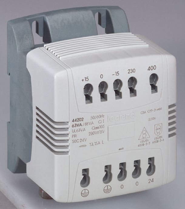
CONTENTS
                 TRANSFORMER FUNCTIONS AND TYPES
                          Why use a transformer?��������������������������������������������������������������������������������� 2
                          How transformers work��������������������������������������������������������������������������������� 2

                 FUNCTIONS
                          Insulation��������������������������������������������������������������������������������������������������������� 3
                          Change of voltage������������������������������������������������������������������������������������������� 4
                          Secondary functions��������������������������������������������������������������������������������������� 5

                 TRANSFORMER TYPES
                          By insulation level������������������������������������������������������������������������������������������� 6
                          Standard insulation����������������������������������������������������������������������������������������� 6
                          Improved insulation ��������������������������������������������������������������������������������������� 6
                          By application ������������������������������������������������������������������������������������������������� 7
                          Control transformers������������������������������������������������������������������������������������� 7
                          Equipment transformers ������������������������������������������������������������������������������� 7
                          Standard installation transformers��������������������������������������������������������������� 7
                          Special installation transformers (Medical)������������������������������������������������� 7

                 STANDARDS
                          Master panel��������������������������������������������������������������������������������������������������� 8

                 INSTALLING TRANSFORMERS
                          Series-parallel connection��������������������������������������������������������������������������� 10
                          Protection on the primary and secondary��������������������������������������������������� 11
                          Tapping points on the primary��������������������������������������������������������������������� 12
                          No-load voltage – on-load voltage��������������������������������������������������������������� 13
                          Making current ��������������������������������������������������������������������������������������������� 15
                          Power: effect of cos φ����������������������������������������������������������������������������������� 16
                          Efficiency������������������������������������������������������������������������������������������������������� 17
                          Transformer losses��������������������������������������������������������������������������������������� 18
                          Temperature class ��������������������������������������������������������������������������������������� 19
                          Instantaneous power ����������������������������������������������������������������������������������� 19
                          Derating according to the ambient temperature ��������������������������������������� 20
                          Miscellaneous questions ����������������������������������������������������������������������������� 22

                 SIZING OF CONTROL AND EQUIPMENT TRANSFORMERS ��������������������� 23
                 EXAMPLES OF APPLICATIONS WITH TRANSFORMERS
                          ELV circuits (reminder of safety voltages according to the humidity
                                        conditions)��������������������������������������������������������������������������������� 24
                                        1- Safety extra-low voltage (SELV) ����������������������������������������� 24
                                        2- Protective extra-low voltage (PELV)����������������������������������� 24
                                        3- Functional extra-low voltage (FELV)����������������������������������� 24
                          Change of neutral earthing system������������������������������������������������������������� 24

                                                                                   LV/LV TRANSFORMERS TECHNICAL GUIDE                              1
WWW.LEGRAND.FR
TRANSFORMER
    FUNCTIONS AND TYPES

    WHY USE A TRANSFORMER?                    HOW TRANSFORMERS WORK
    Transformers are used to transfer         Transformers consist of a winding called the primary and a winding called the
    electricity from a primary circuit to a   secondary.
    secondary circuit via a magnetic field.   A variable speed generator connected to the primary winding causes a current
    A secondary circuit can therefore be      circulating in the turns of this winding, which creates a magnetic field that varies over
    created with expected characteristics     time.
    and functions, and 2 main functions in      Primary winding                                               Secondary winding
    particular:                                     N1 turns                                                       N2 turns
    - Isolation
    - Change of voltage                               Primary
                                                                                 Magnetic Φ                           Secondary
    These 2 functions can be combined (eg:            current                                                   I2
                                                                I1                  flux                                current
    isolating transformer on 230 V primary/
    24 V secondary), although most
    applications only need the isolation
    function (eg: 230 V primary/230 V                Primary
    secondary).                                      voltage                                                         Secondary
                                                        U1                                                            voltage
                                                                                                                        U2

                                                                                    Core

                                              This magnetic field, channelled by a ferromagnetic core, passes through the secondary
                                              winding. Each turn in the secondary winding then creates a new induced voltage (back
                                              electromotive force).
                                              This secondary circuit can then be used to supply another voltage and a given power.
                                              Electricity is therefore transferred from the primary circuit to the secondary circuit
                                              by means of magnetic energy, which allows this secondary circuit to be electrically
                                              “isolated”.
                                              Changes of voltage are linked to the number of turns in the primary and secondary
                                              windings.
                                              Isolation is represented schematically by the space between the primary and
                                              secondary circuit, and in the diagram below, by the space between the windings and
                                              the magnetic body.

                                                     Primary voltage U1                                Secondary voltage U2

2
FUNCTIONS

Isolation

Isolation requires physical separation between the primary            Thanks to isolation of the secondary circuit, the same fault
circuit and the secondary circuit, which is achieved by insulated     situation will not allow an earth loop, and therefore no difference
components and/or distance in the air between conductive              in potential will be felt by the person: in this case the secondary
elements, and between conductive elements and exposed                 circuit is said to be “floating”, and will not be dangerous, even
conductive parts.                                                     with voltages higher than 50 V.
This function can protect people against indirect contact.            According to the standards, this ability to protect people
- the electrical power made available in buildings always has         without an additional device is only possible if it involves
one of its poles that is connected to earth (neutral). Hence, in TT   reinforced insulation or double insulation (see section
system for example, if a phase accidentally touches accessible        “Transformer types”)
conductive parts (machine body), any contact with this metal
part will offer a possible earth loop by passing through the
body, and then becomes dangerous → The use of RCCBs or
RCBOs is then mandatory.

                                                                                        Fault on a
                                                                                        connection
                                   P

                                              230 V

                                   N
                                                       Physical separation
                                                      between primary and
                                                           secondary
                                    Earth                                                  Earth

                                                                        FUNCTIONS       LV/LV TRANSFORMERS TECHNICAL GUIDE                  3
     WWW.LEGRAND.FR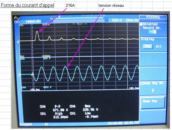
FUNCTIONS

    Change of voltage

    The equation U2/U1 = N2/N1 defines the
                                                         Primary winding                                   Secondary winding
    change of voltage obtained.
                                                             N1 turns                                           N2 turns
    U1 and U2 are the primary and secondary
    voltages, N1 and N2 represent the                           Primary
                                                                                       Magnetic Φ                 Secondary
    number of turns in the primary and                          current
                                                                          I1                                I2      current
                                                                                          flux
    secondary.
    This function can either adapt the
    installation voltage to the voltage                      Primary
                                                             voltage
    permitted by the equipment (400 V →                         U1
                                                                                                                 Secondary
                                                                                                                  voltage
    230 V or vice versa, or even other                                                                              U2
    voltages), and also lower the voltage
    to safe levels: in the latter case we talk
    about extra-low voltage (ELV: < 50 V AC).
                                                                                           Core

    In the latter case of extra-low voltages,
    the transformer can directly protect
                                                                                                           Safety voltage
    people by ensuring contact with both
    secondary poles is safe.                                P
    According to the regulations, this
    ability is verified without additional                                                          24 V
                                                                          230 V
    equipment if the installation satisfies
    the requirements concerning Safety
    extra-low voltage (SELV: see page 25).                  N
                                                                                   Circuit separation
    The combination of the isolation function                                          (isolation)
    and ELV offers a high level of safety for
    people.                                                 Earth                                                 Earth

            The auto-transformer is the
            easiest way to change voltage,
            but it does not provide any
    safety because it does not incorporate
    any electrical isolation between the
    power supply circuit and load circuit
    (only 1 winding for the primary and
                                                 Input
                                                             Pri

    secondary connection).
    It does however prove an economical
                                                                       Sec

                                                                                  Output
    solution if only the voltage needs to be
    changed.

4
Secondary functions

FILTERING ELECTROMAGNETIC INTERFERENCE
A standard isolating transformer offers minimal ability to filter electromagnetic interference.
However, to increase this ability, it is possible to insert an electrostatic shield between the primary and secondary windings, that can be
connected to earth.
Its efficacy depends on the primary/secondary capacitance, which itself depends on the transformer construction topology. The
lower the capacitance is, the more effective the transformer will be in weakening propagation of interference between the primary
and secondary.
Filtering interference has applications in large retail developments for example, in order to eliminate 3rd order harmonics emitted
by fluorescent lighting.
Also in the medical sector, to isolate the main building from interference generated in other sectors: hydrotherapy, ionising
radiation etc, and in industry, when there is a need to isolate sensitive sites, such as computer rooms, measurement laboratories,
computer-controlled machines, etc.

                                                                         FUNCTIONS        LV/LV TRANSFORMERS TECHNICAL GUIDE                  5
     WWW.LEGRAND.FR
TRANSFORMER
    TYPES

    By insulation level

    There are different insulation levels for transformers.

    STANDARD INSULATION
    This consists of separation between windings and between winding and earth with sufficient insulation thicknesses or distances
    to ensure compliance with minimum insulation requirements. A standard isolating transformer cannot claim to keep people safe
    without extra equipment.
    This insulation is also called basic insulation.

    IMPROVED INSULATION
    There are 2 possible types:
    ■■ Reinforced insulation
    Consisting of increased insulation thickness (foil/air insulation), between the primary and secondary circuits.
    ■■ Double insulation
    Consisting of the basic insulation plus extra insulation. This is mainly used for the insulation between the primary and secondary
    via a metal conductive part => Eg: Basic insulation between the primary and metal conductive part and extra insulation between
    the metal conductive part and the secondary (the metal conductive part is often the magnetic body).
    From the point of view of the standards, only transformers complying with this latter category can claim to protect people indirectly
    without additional devices.

                                                                           STANDARDS
                                     NAME                                                                             SYMBOL
                                                        NAME OF STANDARD             INSULATION TYPE

     STANDARD              Isolating transformers      IEC/EN 60076-11
                                                                                  Basic insulation
     INSULATION            Control transformers        IEC/EN 61558-2-2

                                                                                                              A bar “---” is added
                                                                                  Reinforced insulation       between the 2 circles
     IMPROVED              Isolating transformers      IEC/EN 61558-2-4           Basic insulation + extra
     INSULATION            Safety transformer          /2-6/2-8/2-5/2-15          insulation: double
                                                                                  insulation

6
By application

CONTROL TRANSFORMERS                                              STANDARD INSTALLATION TRANSFORMERS:
These transformers comply with the requirements concerning        These are simple isolating transformers. They comply with
control contactors, relays, etc. The minimum characteristics      IEC/EN 60076-11.
are covered by standard IEC/EN 61558-2-2, with for example
                                                                  This type of transformer is suitable for the requirements of
a maximum voltage drop, the indication of the permissible
                                                                  changing voltage or neutral earthing systems that do not need
instantaneous power.
                                                                  reinforced insulation or double insulation. It is essential to add
For the Legrand range, these transformers comply with the         a device to protect people.
“isolation” standards IEC/EN 61558-2-4 for secondaries higher
than 50 V or “safety” type.                                       TRANSFORMERS FOR MEDICAL LOCATIONS:
IEC/EN 61558-2-6 for secondaries lower than 50 V.
                                                                  These are transformers for separating specific circuits.
                                                                  In addition to complying with IEC/EN 61558-2-4, they also
EQUIPMENT TRANSFORMERS
                                                                  conform to EC/EN 61558-2-15 which notably requires limitation
These transformers do not need to comply with “control”           of the secondary/earth leakage current to 0.5 mA at no load,
standard IEC/EN 61558-2-2, and are particularly suitable for      limitation of the inrush current, presence of an electrostatic
fitting in a special enclosure, often physically connected to a   shield, presence of elements for temperature monitoring.
device.

                                                         TRANSFORMER TYPES          LV/LV TRANSFORMERS TECHNICAL GUIDE                 7
     WWW.LEGRAND.FR
STANDARDS

    Transformers are subject to standardisation, and must therefore comply with the standards.
    At present, a single document, IEC 61 558, examines the question from all angles and takes account of the majority of application
    scenarios.

    DEVELOPMENTS IN THE STANDARDS                                         OTHER STANDARDS GOVERNING TRANSFORMERS
    All the publications have now been gathered into a single             - IEC 60 076-11
    document: IEC 61 558. This contains two sections, making it              for dry-type transformers.
    easier to use.                                                        - UL 5085
    Section 1 for the general rules. Section 2 which gives instructions      for transformers    for   general   use,   including   control
    to users so they can comply with regulatory constraints or               transformers.
    requirements of the standards. Section 2 is itself divided into       - CSA C 22.2 no. 66
    several parts, at least three of which are relevant to us:               same as above.
    - Part 2.2: Control transformers.                                     - UL 60 950
    - Part 2.4: Isolating transformers for general use.                    CAN/CSA C 22.2 no. 60 950.00
    - Part 2.6: Safety transformers for general use.                        IEC 60 950/EN 60 950
                                                                             which specify the rules for dealing with information technology
    - Part 2.15: Transformers for medical locations.
                                                                             equipment.
    Transformer standards are identified by symbols, which are
                                                                          - IEC 1204/EN 61 204
    also standardised.
                                                                             which explains the performance characteristics and safety
                                                                             requirements for low-voltage power supply devices with DC
                                                                             output.
                                                                          - EN 61 131.2
                                                                             governs programmable controllers, equipment test
                                                                             requirements and especially the power supply values, in AC
                                                                             and DC, of CPUs.

8
TRANSFORMER STANDARDS
There are various standards which cover transformers. ■■ Definitions:
The applicable standard is determined by the transformer - Electric shock: physiopathological effect resulting from
function(s). These functions are as follows: current passing through the human body.
■■ Change of voltage: - Direct contact: contact between people and live parts.
Isolating transformer (basic insulation between - Indirect contact: contact between people and conductive parts
primary and secondary). that have accidentally become live as a result of an insulation
fault.
Autotransformer (no insulation between primary In short:
and secondary). Isolating transformers
Main transformers (single-phase and three-phase)
used for protection EN 61 558-2-4
against electric
■■ Control circuit power supply: Safety transformers (single-phase
shock
and three-phase) EN 61 558-2-6
Control transformer (basic insulation between
primary and secondary). Control transformers EN 61 558-2-2
Main transformers
Transformers for medical locations
used for functional
■■ Protection against electric shock EN 61 558-2-15
reasons
Protection against direct contact and indirect contact: Isolating transformers EN 60 076-11
Safety transformers
(reinforced insulation between primary and
secondary, no-load voltage < 50 V).
Protection against indirect contact:
Isolating transformers
(reinforced insulation between primary and
secondary).
Isolating transformers for medical locations.
Transformer functions can either be determined by the
equipment designer or be imposed by the installation
instructions or equipment standard. The range of standards
applicable to transformers is summarised in the table opposite.
STANDARDS LV/LV TRANSFORMERS TECHNICAL GUIDE 9
WWW.LEGRAND.FRINSTALLING
TRANSFORMERS
Series-parallel connection
The secondary voltages U1 and U2 should be the same for
O2 parallel connection.
Secondary 2: U2
Primary O1
I2
Secondary 1: U1
I1
SERIES CONNECTION PARALLEL CONNECTION
Link between terminals E2 and S1, operating voltage between Link between terminals E1 and E2
terminals E1 and S2: and link between terminals S1 and S2,
The voltage obtained is the sum of the voltages of both operating voltage between terminals E1 and S2:
windings, the nominal power stays the same.
The voltage obtained is the voltage on each winding,
the nominal power stays the same.
I1 I2 O1 O2 I1 I2 O1 O2
Output with series Output with parallel
connection connection
U output = U1 + U2 U output = U1 = U2
Nominal power Nominal power
Some transformers are supplied with an extra link. This is provided for the requirements of certain installations that require a
link between the secondary and the conductive part.
Caution, this link must not be fitted
between the transformer primary terminals.
10Transformer supply line protection
A transformer is a device that cannot generate overloads. Its supply line only needs protection against short-circuits. Short-circuit
protection is mandatory for all installation scenarios and must be installed at the head of the line.
When a transformer is energised, the magnetic circuit may become saturated, depending on where the power supply sine wave
is on energisation. This saturation causes significant overcurrents, that can reach as much as 25 times the nominal current,
decreasing over 4 to 5 periods (approximately 10 ms).
To avoid any problem with the protection tripping, fit a delayed protection device on the primary, with either an aM fuse or D circuit
breaker.
Transformer protection
In accordance with IEC/EN 61558, transformers must be protected on the secondary against overloads and short-circuits. As the
standards do not impose particular requirements, the manufacturer can choose what protection device to use and where to place
it. Legrand recommends protection on the secondary. The rating, type and location of the protection device is stated on the front
of the equipment.
Working line protection
(after transformer secondary)
This line must be protected against:
- Overloads: check that the protection rating chosen is the same or lower than the transformer secondary current
- Short-circuits: check that a short-circuit at the furthest point on the line will trip the protection device in less than 5 seconds (NF
C 15-100, paragraph 434)
In cases where the transformer only supplies one working line, and provided that the calculations have demonstrated perfect
compatibility, the transformer protection (on the secondary) and line protection can be combined. A single protection device thus
performs both functions.
In cases where the transformer supplies several working lines, overloads and short-circuits must be calculated individually for
each line.
INSTALLING TRANSFORMERS LV/LV TRANSFORMERS TECHNICAL GUIDE 11
WWW.LEGRAND.FRINSTALLING TRANSFORMERS
Tapping points on the primary
Some transformers and power supplies have tapping points on the primary.
SCENARIO 1: SCENARIO 2: SCENARIO 3:
The incoming voltage at the transformer The load power is lower than the nominal The output current, especially at a high
primary terminals is different from 230 V power. The voltage drop expected value, causes a voltage drop in the cables
or 400 V: see the wiring diagram below. in the transformer is not therefore supplying the equipment. If the cables are
fully consumed and the voltage at the long, this loss can prevent the equipment
transformer secondary may then be a bit supplied from working properly. The
too high. In this case, proceed as if the working voltage should therefore be
input voltage at the primary terminals increased a little. To do this, proceed as
were 245 V (rather than 230 V) or 415 V if the input voltage at the secondary were
(rather than 400 V) to decrease the 215 V (rather than 230 V) or 385 V (rather
working voltage. than 400 V).
In all 3 cases, the input voltage should be corrected in the transformer to adjust the secondary voltage.
415 V
400 V
Incoming voltage at the transformer
385 V
primary
245 V
and 230 V
215 V
use of tapping points on the transformer
+ 15 0 - 15 230 400
primary terminals
Primary
12No-load voltage
This is the secondary voltage obtained A transformer is not a voltage regulator.
when the transformer is supplied at The voltage drop is expressed as a %.
the rated primary voltage and the rated
Do not confuse this with Usc!! The Usc is used to define the Isc short-circuit current
frequency, without a secondary load.
value at the transformer primary. It is used to check compatibility of the line Isc with the
When the transformer is brought on load, breaking capacity of the supply line protection device.
the current and resistance in the winding
(Isc at the transformer primary = Ip/Usc – Example: nominal supply current in the 100 A
wires causes a voltage drop. This voltage
transfo and Usc = 2% → Isc = 5000 A at the transformer primary).
drop marks the difference between the
no-load voltage and the on-load voltage.
The on-load voltage corresponds to the Let’s take the case of a transformer Cat. No. 0 427 87.
voltage obtained when the transformer Its stated voltage drop for cos φ 1 is 10.7% (see technical characteristics table in the
is loaded at its nominal rating. If the catalogue).
transformer is not fully loaded, the This means that if the primary voltage is indeed 230 V or 400 V and the transformer is
expected voltage drop is only partly loaded with 100% of the nominal power (100 VA in our example), we get:
consumed and the transformer on-load
On-load voltage 230 V (+/- standard tolerances)
voltage will therefore be higher.
No-load voltage: 230 V + 10.7% = 255 V
Note: For EN 60076-1 power But if the transformer is only loaded with 50% of the nominal power (or 50 VA), the
transformers, the rated voltage secondary voltage will not then be 230 V on load, but 242 V.
stated on the transformer
corresponds to the no-load voltage. 280 V
For EN 61558 transformers, the rated
voltage stated on the transformer 275 V
corresponds to the on-load voltage. 270 V
265 V
260 V
255 V
250 V
245 V
240 V
235 V
230 V
225 V
220 V
0% 10% 20% 30% 40% 50% 60% 70% 80% 90% 100%
INSTALLING TRANSFORMERS LV/LV TRANSFORMERS TECHNICAL GUIDE 13
WWW.LEGRAND.FRINSTALLING TRANSFORMERS
No-load voltage (continued)
If, in addition, the input voltage is not 230
V, but higher; for example power supply 280 V
245 V (the voltage delivered by the power
275 V
grid may be 230 V +10% = 253 V), the
voltage should be increased accordingly 270 V
at the secondary (blue line on the 265 V
diagram opposite), which will give:
260 V
- 245 V at 100% of the nominal power
- 258 V at 50% of the nominal power 255 V
- 265 V at 20% of the nominal power 250 V
- 270 V at no-load 245 V
If use of the secondary voltage requires 240 V
a more finely-tuned voltage (supplying
relays for example), we recommend 235 V
choosing a transformer with tapping 230 V
points from the control and signalling
225 V
transformer range or asking for a
transformer configured to your exact 220 V
requirements. In this case, we would 0% 10% 20% 30% 40% 50% 60% 70% 80% 90% 100%
replace the 0 427 87 with a 0 442 63.
With a 0 442 63 transfo for the same
application as in the above example:
280 V
Supply voltage 245 V between the +15 V
and 230 V terminals 275 V
0 442 63 → 270 V
- 230 V at 100% of the nominal power 265 V
- 240 V at 50% of the nominal power 260 V
- 247 V at 20% of the nominal power 255 V
- 251 V at no-load
250 V
245 V
240 V
235 V
230 V
225 V
220 V
0% 10% 20% 30% 40% 50% 60% 70% 80% 90% 100%
14Making current
Powering up a transformer causes very rapid magnetisation of the magnetic circuit in the transformer. The magnetising current
(or making current) can be very high (up to 25 In).
It is a transient current (a few milliseconds) that reaches its maximum if starting occurs when the voltage sine wave passes
through “0”. The remanent induction is then also at maximum. In this exact scenario, in a 1/2 period (10 ms), you should provide
twice the nominal induction.
In conclusion, the value of the making currents is very random. It depends on the instant when power-up occurs.
Caution, powering up a transformer is likely to create interference on the primary supply and the secondary supply. On distribution
networks and industrial networks, the making currents can for example create unwarranted trips and significant voltage surges.
Readout on start-up of a 142557 transformer (Single-phase 6.3 kVA) with 230 V power supply.
(Primary nominal current 28.5 A)
Inrush current waveform supply voltage
INSTALLING TRANSFORMERS LV/LV TRANSFORMERS TECHNICAL GUIDE 15
WWW.LEGRAND.FRINSTALLING TRANSFORMERS
Power: effect of cos φ (P in W)
The voltage and current are in the form of a sine wave.
Voltage
Depending on the equipment used, they can be time-shifted by
an angle φ called the “phase shift angle”. Current
Power
This shift is due to the fact that the load consists of a resistive
part (resistance), that corresponds to the circuit active power Average power
and a reactive part (reactance), that corresponds to the reactive
power (inductive and/or capacitive component).
The voltage as a function of time is written: 180 V
170
A
u(t) = V sin(ωt) 160
W Cos Phi 0.8
150
The current is written: 140
130
i(t) = I sin(ωt + φ) (φ phase shift in radians) 120
110
The active power is written: 100
90
P(t) = u(t) x i(t) 80
70
To get round this phase shift effect, the stated transformer 60
power ratings are average Ps (nominal and permissible 50
40
instantaneous), and are expressed in VA, not in W, with the 30
equation: 20
10
Apparent power P in VA = UxI 0
-10 0 5 10 15 20 25
Active power P in W = UxIxcos(phi) in single-phase, -20
-30
and = UxIx√3cos φ in three-phase
The graphs opposite show what the active power becomes with 180 V
170
different cos φ for: A
160
W Cos Phi 0.4
- a voltage of 12 V (12 V rms – peak 17 V) and 150
140
- a current of 7 A (7 A rms – peak 10 A). 130
120
If the use behind the transformer has a low cos φ, a transformer 110
100
with a higher nominal power rating should be provided to 90
correct this. 80
70
For example, fluorescent tubes without compensation usually 60
50
have a cos φ of 0.5. The tube power rating should be halved in 40
order to define the transformer power rating. 30
20
A few examples of cos φ: 10
0
- Incandescent lighting cos φ = 1 -10 0 5 10 15 20 25
-20
- Fluorescent lighting with electronic ballast cos φ = 1 -30
- Fluorescent tube lighting: with compensation cos φ = 0.85 and
without compensation cos φ = 0.5
- Motors: normal operation cos φ = 0.75 to 0.92 and on start-up
cos φ = 0.3 to 0.5. If nothing is indicated, it is prudent to use
cos φ = 0.8.
16Efficiency
Efficiency can be used to characterise the proportion of losses
180 V
170 compared to the power consumption
A
160
W Cos Phi 1
150
140
130 Efficiency is written:
120
110 active P supplied to the secondary
100 =
90 total active P absorbed
80
70
60 U2 x I2 x Cos ф
50
=
40
U2 x I2 x Cos ф + No-load loss + load loss
30
20
10 Hence, a transformer without much load will not be very
0
-10 0 5 10 15 20 25 efficient: the losses become significant (especially the no-load
-20 losses which remain constant) compared to the power
-30
consumed by the load.
180 V This efficiency will also be degraded if this load is significantly
170
A phase-shifted (cos ф < 1).
160
W Cos Phi 0.6
150
140
130
120 Reactive power (in Var) Apparent power:
110
100 UI sinφ P = UI
90
80
70
60
50
40
30
20
10
0
-10 0 5 10 15 20 25 Active power
-20 φ UI cos φ
-30
180 V
170
A
160
W Cos Phi 0.2
150
140
130
120
110
100
90
80
70
60
50
40
30
20
10
0
-10 0 5 10 15 20 25
-20
-30
INSTALLING TRANSFORMERS LV/LV TRANSFORMERS TECHNICAL GUIDE 17
WWW.LEGRAND.FRINSTALLING TRANSFORMERS
Transformer losses
A transformer’s losses are made up of the no-load losses and load losses:
1 NO-LOAD LOSSES 2 LOAD LOSSES
Often called iron losses. Load losses (or Joule effect losses) result from heat caused
They occur in the ferromagnetic core. They depend on the by the current flowing in the primary and secondary windings.
frequency and the supply voltage. These losses are proportional to the square of the transformer
load.
They do not depend on the load at the transformer secondary.
They represent the energy dissipated in the form of heat caused
Magnetisation of the laminations is accompanied by energy
by the current flowing in the primary winding and the secondary
losses in the form of heat. There are two types:
winding.
- Hysteresis loss: magnetisation of the material is not totally
Since the winding resistance varies as a function of the
reversible. The AC power supply creates a change of flux
temperature(*), the load losses are higher when the transformer
direction on each voltage half-wave, forcing the iron atoms
has been working for several hours and the temperature has
to permanently rearrange themselves. This causes friction,
stabilised, compared to start-up.
which generates losses. These are hysteresis losses. They
depend on the magnetising current and the material memory. In the LEGRAND catalogue, load losses are given at stabilised
temperature at nominal load.
- Eddy current losses: are caused by induced currents, at right-
angles to the electrically-conducting lamination, which try to
cancel out a magnetic field passing through it. These induced
currents increase with the size of the surface area crossed by
this magnetic field. Eddy current losses depend on the square
of the lamination thickness. This is why the transformer
magnetic circuit is not formed from a block of steel, but
created by a stack of laminations isolated from one another.
TOTAL LOSSES = NO-LOAD LOSSES + LOAD LOSSES
(*): RT1 = RT0 (1+ ( (T1-T0))
RT1 is the winding resistance at temperature T1
RT0 is the winding resistance at temperature T0
is the temperature coefficient. This depends on the material used.
(For copper, a = 3.92927308 x 10⁻³K-1 at Tambient 20°C, for aluminium, = 3.90625 x 10⁻³K-1 at Tambient 20°C)
18Temperature class
A transformer’s temperature class indicates that in normal use, at an ambient temperature of 25°C (if no ambient temperature is
specified, or at the ambient temperature indicated by the manufacturer if displayed on the product), the transformer windings will
not exceed the following temperatures:
Class B: 130°C
Class F: 155°C
Class H: 180°C
Maximum instantaneous power (MIP)
A transformer’s maximum instantaneous power is a “peak” power that the transformer is capable of providing for a very brief time
(from a few ms to a few seconds).
This characteristic is important when it comes to sizing the transformer, as it must be sufficient to cope with inrush current from
certain inductive loads.
(See sizing on page 24)
INSTALLING TRANSFORMERS LV/LV TRANSFORMERS TECHNICAL GUIDE 19
WWW.LEGRAND.FRINSTALLING TRANSFORMERS
Derating according to ambient temperature
When the ambient temperature increases, it is sometimes necessary to reduce the transformer working power to comply with its
temperature class (see “Temperature class” section).
EQUIPMENT TRANSFORMERS
■■ Power derating according to ambient temperature
(conforming to the class, not conforming to EN 61558)
700 VA 630 VA
450 VA
310 VA
220 VA
160 VA
600 VA
100 VA
63 VA
40 VA
500 VA
Power
400 VA
300 VA
200 VA
100 VA
0 VA
25°C 30°C 35°C 40°C 45°C 50°C 55°C 60°C 65°C 70°C
Ambient T°
20CONTROL AND SIGNALLING TRANSFORMERS
■■ Power derating according to ambient temperature
(conforming to the class, not conforming to EN 61558)
2700 VA 2500 VA
1600 VA
2600 VA 1000 VA
2500 VA 630 VA
400 VA
2400 VA 250 VA
2300 VA 160 VA
100 VA
2200 VA 63 VA
40 VA
2100 VA
2000 VA
1900 VA
1800 VA
1700 VA
1600 VA
1500 VA
1400 VA
1300 VA
Power
1200 VA
1100 VA
1000 VA
900 VA
800 VA
700 VA
600 VA
500 VA
400 VA
300 VA
200 VA
100 VA
0 VA
25°C 30°C 35°C 40°C 45°C 50°C 55°C 60°C 65°C 70°C
Ambient T°
INSTALLING TRANSFORMERS LV/LV TRANSFORMERS TECHNICAL GUIDE 21
WWW.LEGRAND.FRMISCELLANEOUS
QUESTIONS
■■ Sometimes no-load voltage is detected between the ■■ Sometimes problems occur when connecting boilers.
conductive part and neutral:
In most cases, the problem is resolved by connecting the
This may be a simple capacitive voltage: on trying to connect a neutral to the conductive part.
load, the voltage collapses immediately.
However, not all boilers have the same installation instructions,
It may be due to contamination of the conductive part. In this so it is essential to refer to the boiler manufacturer’s
case, a measurement elsewhere than on the transformer instructions for use.
between the conductive part and neutral also indicates voltage.
This means it is a problem with the installation.
22SIZING THE
TRANSFORMER
(CONTROL)
Every circuit needs a specific transformer power rating: this is Empirically and to simplify matters, this power is calculated
sizing. using the following equation:
In the case of Control transformers, it is not enough to add up Pinrush = 0.8 x (Σ Pm + Σ Pv + Pa)
the power ratings of the load circuits. It is also necessary to take Σ Pm: sum of all the contactor holding powers
account of the maximum instantaneous power, which should be
Σ Pv: sum of all the indicator powers
sufficient to take on the inrush power of the loads (essentially
contactor coils, but also various motors or actuators). Pa: inrush power of the largest contactor
For equipment including automation devices, the appropriate Example: A machine-tools control enclosure containing:
transformer should primarily be selected on the basis of • 10 contactors for 4 kW motors, with 8 VA holding power
2 parameters: • 4 contactors for 18.5 kW motors, with 20 VA holding power
- The maximum power needed at a given moment (inrush • 1 contactor for 45 kW motors, with 20 VA holding power,
power) 250 VA inrush power at cos φ 0.5
- The Cos φ (see page 16 Power: effect of cos φ) • 12 remote control relays, with 4 VA holding power
In addition, it should be necessary to confirm your choice with • 45 LED indicators, with 1 VA consumption
one of the following parameters:
This gives the following calculations:
- Permanent power
Σ Pm = 10 X 8 VA = 80 VA
- Voltage drop (see page 13 No-load voltage)
4 x 20 VA = 80 VA
- Ambient temperature (see page 19)
1 x 20 VA = 20 VA
To determine the inrush power, we have agreed the following
12 x 4 VA = 48 VA
factors:
228 VA
- Two inrushes cannot happen at the same time
Σ Pv = 45 x 1 VA = 45 VA
- The power factor cos φ is 0.5
Pa = 250 VA
- 80% maximum of devices are supplied at the same time.
Pinrush = 0.8 (228 + 45 + 250) = 418 VA at cos φ 0.5
For control transformers, simply read the size from the table below:
RATED M.I.P AT COS Φ =
POWER (VA) 0.2 0.3 0.4 0.5 0.6 0.7 0.8 0.9 1
40 69 63 58 55 52 50 49 49 58
63 120 110 98 90 85 81 78 78 89
100 210 180 170 150 140 140 130 130 150
160 390 340 300 270 250 230 220 220 230
250 540 490 450 420 400 380 370 370 440
400 1900 1400 1200 980 800 800 700 600 600
630 2200 1700 1400 1000 1000 900 800 800 700
1000 3400 2800 2300 2000 1800 1600 1500 1400 1300
1600 14,300 12,000 10,300 9100 8200 7500 7000 6600 6800
SIZING THE TRANSFORMER (CONTROL) LV/LV TRANSFORMERS TECHNICAL GUIDE 23
WWW.LEGRAND.FREXAMPLES OF APPLICATIONS
WITH TRANSFORMERS
ELV circuits
The ELV limits are defined in the regulations:
in AC: U ≤ 50 V in DC: U ≤ 120 V
DISCONNECTION PROTECTION PROTECTION
AND SHORT- AGAINST
VOLTAGE RANGE POWER SUPPLY EARTHING AGAINST DIRECT RECEIVERS WHEN SUBMERGED
CIRCUIT INDIRECT CONTACT
PROTECTION: CONTACT
Safety transformer PROHIBITED Of all live conductors NO if U≤25 VAC NO if U≤25 VAC - U25 VAC YES if U>25 VAC volumes 0, 1 and 2 in bathrooms
(Safety) (or 60 VDC) (or 60 VDC) - protection against direct contact
Z must always be guaranteed
Safety transformer Live conductor Of all live conductors NO if U≤12 VAC NO if U≤12 VAC USE PROHIBITED
PELV IEC/EN 61558-2-6 connected to earth (or 30 VDC) (or 30 VDC)
(Protection) YES if U>12 VAC YES if U>12 VAC
(or 30 VDC) (or 30 VDC)
Z
Transformer of Live conductor Of all live conductors YES (RCD) YES (IP 2x devices) USE PROHIBITED
FELV
indeterminate connected to earth
(Functional)
origin
Z
Change of neutral earthing system
Example of changing from an IT system without neutral → TN-S with creation of neutral.
Standard system diagram of an island with three-phase TN-S system (can be applied to a single-phase system).
IT or TT TN-S
DR-1A
L1 L1
L2 L2
L3 L3
N
PE PE
Connection of protective
conductors
Equipotential link between
conductive parts
24To know more,
check export.legrand.com
All technical data of the products inside this workshop specifications book are available
on : https://www.export.legrand.com/en
>Click on >DOCUMENTATION & SOFTWARE
>Documentation
LV/LV TRANSFORMERS
FURTHER DOCUMENTATION ..... TECHNICAL GUIDE 25FOLLOW US
ON
www.legrand.com
www.youtube.com/legrand
twitter.com/legrand_news
Head office
and International Department
EXB19045 - November 2019
87045 Limoges Cedex - France
Tel: + 33 (0) 5 55 06 87 87
Fax: + 33 (0) 5 55 06 74 55You can also read