Maintenance Manual 4 -Inch Internal Valve F635 Series
←
→
Page content transcription
If your browser does not render page correctly, please read the page content below
Maintenance Manual
4½-Inch Internal Valve
     F635 Series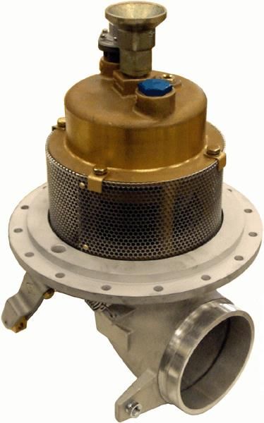
Meggitt Fuelling Products
                                                                          Maintenance Manual
                                                         4½-Inch Internal Valve – F635 Series

                                                   LIST OF EFFECTIVE PAGES
On a revised page, the portion of text or illustrations affected by the change is indicated by a vertical line in the outer margin
of the page. When a revision is issued, the entire document is reissued with the current revision number and date shown on
all pages. For major revisions, the basic number is incremented. For minor revisions, the number following the decimal is
incremented. Dates of issue for original and subsequent revisions are as follows:

                        Original 1.0 ....................................................................................................... 11/01/2004
                        Revision 1.1 ...................................................................................................... 12/15/2005
                        Revision 1.2 ...................................................................................................... 02/01/2006

The total number of pages in this technical document is 23 consisting of the following:

                                                                                   Title, 2 – 23

                                                                      TABLE OF CONTENTS
SUBJECT                                                                                                                                                                         PAGE

Introduction ........................................................................................................................................................................ 3
Description and Operation .................................................................................................................................................. 3
Fault Isolation ...................................................................................................................................................................... 8
Disassembly ....................................................................................................................................................................... 10
Cleaning ............................................................................................................................................................................. 11
Inspection .......................................................................................................................................................................... 12
Assembly ........................................................................................................................................................................... 13
Push Rod Installation ......................................................................................................................................................... 16
Illustrated Parts List ........................................................................................................................................................... 17

                                                                                                                                    Revision 1.2 – 02/01/2006
Meggitt Fuelling Products
Maintenance Manual
4½-Inch Internal Valve – F635 Series
INTRODUCTION
1. General
This manual provides component maintenance shop instructions for the 4½-Inch Internal Valve (valve).
2. Revision Service
This manual will be revised as necessary to show the current information.
3. Weights and Measurements
Weights and measurements in this manual are expressed primarily in English (U.S. customary) and selected Metric (SI) units.
DESCRIPTION AND OPERATION
1. Description
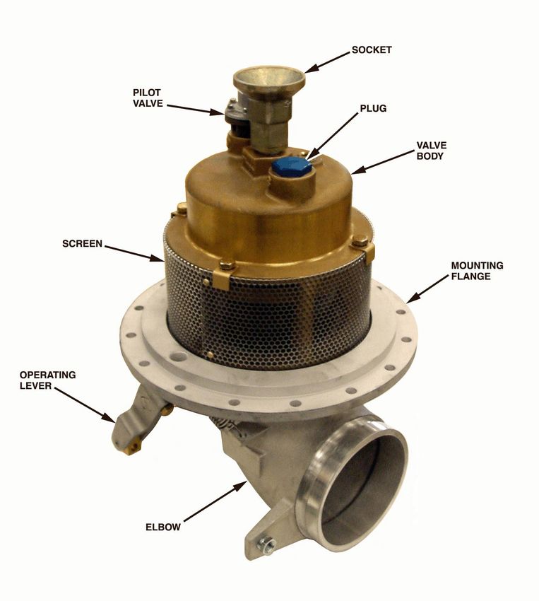
A. The 4½-Inch Internal Valve (valve) (see Figure 1) is designed to provide automatic control as well as normal and
emergency shutoff functions and tank liquid level control with low surge, low pressure drop, and high reliability.
When used with the F613 jet level sensor, fuel pressure pro- vides the actuation force for opening and closing the
valve during tank filling. During bottom loading, the valve is opened by the pressure in the fuel line.
B. The basic valve can be used for off-loading. Single or dual stage tank filling control is available by adding one or
two pilot valves. An operating lever is provided for attachment of a cable to open the valve during off-loading.
2. Operation
A. Starting Fuel Flow into the Tank
1) Basic Valve with no Pilot valves
Open the main valve manually using the operating lever.
2) Single Stage Pilot (F635A)
The pilot valve opens with jet receiving pressure transmitted through a jet level sensor. The main valve opens as
determined by the system flow capacity. The upstream pressure then opens the main piston, establishing flow
into the tank.
Meggitt Fuelling Products
        Maintenance Manual
4½-Inch Internal Valve – F635 Series

       Figure 1. 4½-Inch Internal Valve
Meggitt Fuelling Products
Maintenance Manual
4½-Inch Internal Valve – F635 Series
3) Dual Stage Pilot (F635B)
The primary and secondary pilot valves open with jet receiving pressure transmitted through primary and secondary
jet level sensors. The main valve opens as determined by the system flow capacity. The upstream pressure then
opens the main piston, establishing flow into the tank.
B. Stopping Fuel Flow into the Tank
1) Basic Valve with no Pilot Valves
Close the main valve manually using the operating lever.
2) Single Stage Pilot (F635A)
The primary pilot valve closes when the rising fuel level in the tank reaches the single jet level sensor. The jet
receiving pressure is shut off and the main valve closes.
3) Dual Stage Pilot (F635B)
The primary pilot valve closes when the rising fuel level in the tank reaches the primary jet level sensor. The
primary jet receiving pressure is shut off and the main valve is throttled to, resulting in reduced fuel flow. The
secondary pilot valve closes when the rising fuel level in the tank reaches the secondary jet level sensor. The
secondary jet receiving pressure is shut off and the main valve closes, resulting in an accurate final fuel level in
the tank.
C. Pilot Operation
When the fuel pressure applied to the pilot valve increases to approximately 6 psi, the pilot valve will open. When the pilot
valve opens, the fuel trapped in the main piston chamber is relieved into the tank. Fuel flow into the tank stops when the
fuel level reaches the jet level sensor shutoff point. Pressure to the pilot valve is relieved and the pilot valve closes.
When the pilot valve closes, fuel fills the main piston chamber and the main piston is closed by spring force and fuel
pressure.
D. Off-Loading Fuel
Fuel off-loading is accomplished by manually operating the lever. The lever pushes the main piston to its open position,
allowing fuel to flow.
3. Leading Particulars (Refer to Table 1)
4. Model Variations
Refer to Table 2 for the available valve variations. Refer to the ILLUSTRATED PARTS LIST section for additional details.Meggitt Fuelling Products
Maintenance Manual
4½-Inch Internal Valve – F635 Series
Table 1. Leading Particulars
Service ............................................................................................................................Automotive and Aviation Fuels
Pressures
Operating Pressure Range ............................................................................................................................ to 150 psi
Jet Receiving Pressure (F613) .......................................................................................................... 15 psi (0.5 gpm)
Flow Rate (maximum) ......................................................................................................................................... 1100 gpm
Fluid Temperature ............................................................................................................... –40 to 140EF (–54 to 60EC)
Ambient Temperature ......................................................................................................... –40 to 140EF (–54 to 60EC)
Weight (basic model) (approximate) ................................................................................................... 20 pounds (9,1 kg)
Envelope Dimensions..................................................................................................................................... See Figure 2
Table 2. Model Variations
MOD LETTER DESCRIPTION
(Basic) Manually operated valve, 4½-inch Victaulic inlet, short radius elbow, aluminum weld ring
A Single Stage Pilot – Adds primary pilot valve for simple automatic bottom loading shutoff control
B Dual Stage Pilot – Adds primary and secondary pilot valves for accurate automatic bottom loading
shutoff control
D Without weld ring
E Steel weld ring instead of aluminum
F Long radius elbow instead of short radius.
G Stainless steel weld ring (replaces aluminum weld ring)
J Adds Viton seals
K Adds Victaulic body
M Brass and iron free unitMeggitt Fuelling Products
Maintenance Manual
4½-Inch Internal Valve – F635 Series
Figure 2. Envelope DimensionsMeggitt Fuelling Products
Maintenance Manual
4½-Inch Internal Valve – F635 Series
FAULT ISOLATION
1. General
Refer to Table 3 for fault isolation information. Locate suspected faulty component and take appropriate remedial action.
Table 3. Fault Isolation
FAULT POSSIBLE CAUSE CORRECTIVE ACTION
BOTTOM FILLING OPERATION
Valve will not open Insufficient fuel pressure at pilot valve Check and correct the air pressure supply.
(50, IPL Figure 1)
Pilot valve diaphragm (6, IPL Overhaul or replace the pilot valve.
Figure 2) leaking
Jammed main piston (13, IPL Figure Overhaul the valve.
1) due to contamination
Surging fuel flow Insufficient fuel pressure at pilot valve Check and correct the air pressure supply.
(50)
Valve will not close Jammed main piston (13) due to Overhaul the valve.
contamination
Main piston seal (22) or cap strip Replace the seal and the cap strip.
(42) damaged
Operating cable incorrectly Adjust the operating cable.
adjusted
Incorrectly installed or damaged plug Re-install the plug. Replace the plug if
(31) damaged.
Tension spring (9) missing or Replace or connect the spring.
disconnected
BOTTOM FILLING OPERATION
Internal leakage Main piston seal (22) or cap strip Replace the seal and the cap strip.
(42) damaged Overhaul the valve.
Damaged seat on main piston
(13) or contamination of sealing surfacesMeggitt Fuelling Products
Maintenance Manual
4½-Inch Internal Valve – F635 Series
Table 3. Fault Isolation (continued)
FAULT POSSIBLE CAUSE CORRECTIVE ACTION
Internal leakage Incorrectly installed or damaged plug Re-install the plug. Replace the plug if
(31) damaged.
OFF-LOADING OPERATION
Valve will not open Operating cable incorrectly Adjust the operating cable.
adjusted
Jammed main piston (13) due to Overhaul the valve.
contamination
Main piston seal (22) or cap strip Replace the seal and the cap strip.
(42) damaged
Valve will not close Jammed main piston (13) due to Overhaul the valve.
contamination
Main piston seal (22) or cap strip Replace the seal and the cap strip.
(42) damaged
Operating cable incorrectly Adjust the operating cable.
adjusted
OFF-LOADING OPERATION
Leakage when valve is closed Contaminated pilot valve (50) Overhaul or replace the pilot
(NOTE: Leakage of up to 20 valve.
cc/minute is allowed.)
Excessively worn or contaminated Replace the seal.
main piston packing (28)
Excessively worn or contaminated Replace the quad ring.
quad ring (9)
Damaged seat on main piston Overhaul the valve.
(22) or contamination of sealing
surfaces
Shaft leakage Excessively worn or contaminated Replace the packing.
packing (27)
Excessively worn or contaminated Replace the seal.
seal (40)Meggitt Fuelling Products
Maintenance Manual
4½-Inch Internal Valve – F635 Series
DISASSEMBLY
1. Disassembly of the Valve (Refer to IPL Figure 1)
A. Removing the Plugs or the Pilot Valves
1) Unscrew and remove the plug(s) (33) or the pilot valve(s) (50) and the packings (25) from the valve body (11).
2) For P/N F635B only, remove the orifice (51) and the packing (52).
B. Removing the Screen
Remove the bolts (31) and the retainers (20) securing the screen (23) to the valve body (11). Do not remove the rivets (45).
C. Removing and Disassembling the Elbow
1) Disconnect and remove the spring (9) from the elbow (1) and the lever (3).
WARNING: THE ELBOW AND THE VALVE BODY ARE UNDER HEAVY SPRING PRES- SURE. YOU MUST BE VERY CAREFUL TO
RESTRAIN THEM DURING DISAS- SEMBLY.
2) Remove the bolts (37) and the washers (35), and carefully separate the elbow (1) from the sump plate (15) and
the valve body (1). Remove the spring (19) and the packings (28 and 29).
3) Remove the nut (36), the washer (35) and the bolt (38) securing the lever (3) to the shaft (6). To remove the
link (8), drive out the pin (39).
4) Unscrew and remove the gland (7) from the elbow (1). Remove the seal (40) and the packing (27).
5) Remove the shaft (6), the washer(s) (44) and the cam (2) from the elbow (1).
D. Disassembling the Valve Body
CAUTION: BE CAREFUL TO PREVENT DAMAGING OUTSIDE DIAMETER OF THE NUT ASSEMBLY WHEN HOLDING IT.
1) Use a suitable pin to hold the nut assembly (4) from turning. Unscrew and remove the socket (14) from the
piston shaft (16). Remove the packing (26) from the socket.
2) Remove as a subassembly, the piston (13), the piston shaft (16), the nut assembly (4), the retaining ring (41)
and the rod cap (17) from the valve body (11). Remove the retaining ring, the rod cap, the metering rod and the
nut assembly from the piston.Meggitt Fuelling Products
Maintenance Manual
4½-Inch Internal Valve – F635 Series
3) Remove the packing (30), the cap strip (42) and the piston seal (22) from the valve body (11).
CAUTION: WHEN REMOVING THE BUSHINGS, BE CAREFUL TO AVOID DAMAGING THEIR BORES.
4) If replacement is necessary, use a suitable tool to remove the bushings (1A, 4A and 11A) from their bores.
5) If replacement is necessary, remove the bushings (34 and 43) from the elbow (1) and the sump plate (15).
2. Disassembly of the Pilot Valve (Refer to IPL Figure 2)
1) Remove the screws (8), the washers (9) and the cover (7) from the fitting (1).
2) Remove the diaphragm (6) from the fitting (1).
3) Remove the retaining ring (5), the washer (4), the spring (3) and the poppet (2) from the fitting (1).
CLEANING
1. Cleaning Materials
Refer to Table 5 for recommended cleaning materials. Suitable equivalent cleaning materials may be substituted for the items
listed.
Table 5. Recommended Cleaning Materials
DESCRIPTION SPECIFICATION SOURCE
Brush, Bristle, stiff, nonmetallic –– Commercially available
Dry Cleaning Solvent P-D-680, Type 2 Commercially available
Pick, Teflon –– Commercially available
Plastic Bags –– Commercially available
Tissues, lint-free –– Commercially availableMeggitt Fuelling Products
Maintenance Manual
4½-Inch Internal Valve – F635 Series
2. Cleaning Procedures
WARNING: DRY CLEANING SOLVENT IS FLAMMABLE AND TOXIC TO EYES, SKIN, AND RESPIRATORY TRACT. SKIN/EYE
PROTECTION REQUIRED. AVOID REPEATED/ PROLONGED CONTACT. USE ONLY IN WELL VENTILATED AREAS.
GOOD GEN- ERAL VENTILATION IS NORMALLY ADEQUATE. KEEP AWAY FROM OPEN FLAMES OR OTHER
IGNITION SOURCES.
A. Clean all metal parts by washing thoroughly in dry cleaning solvent. Remove stubborn deposits by scrubbing with a
nonmetallic stiff bristle brush. Brush all threaded areas. Use a Teflon pick to remove obstructions from the ports,
the seal or packing grooves and the flow passages.
NOTE: All of the parts must be free of corrosion, dirt, grease, oil, or any other foreign matter.
WARNING: WEAR EYE PROTECTION WHEN DRYING PARTS WITH COMPRESSED AIR. DO NOT DIRECT AIRSTREAM AT
PERSONNEL OR LIGHT METAL PARTS.
B. Dry parts with clean lint-free tissues or clean, dry compressed air.
C. Package clean parts in plastic bags.
INSPECTION
1. General
A. Under strong light and magnification, visually check all parts in accordance with the general criteria specified in
paragraph 2 below.
B. Repair minor damage in accordance with local standard procedures. If damage is major or be- yond simple repair,
replace the part rather than attempt any extensive repairs.
2. Component Checks (Refer to Table 6)
Table 6. Component Checks
DESCRIPTION
(IPL Figure 1 Item CHECK CRITERIA
No.)
General 1) Visually check all parts as applicable for nicks, cracks, cuts, burrs, corrosion,
breaks, scoring, deformation, dents, thread damage, or any other obvious
defects.
2) Make sure that the ports, passages, recesses and sealing grooves are clean and
unobstructed.
3) Check all sealing and seating surfaces for damage or corrosion which would
affect sealing.Meggitt Fuelling Products
Maintenance Manual
4½-Inch Internal Valve – F635 Series
Table 6. Component Checks (continued)
DESCRIPTION
(IPL Figure 1 Item CHECK CRITERIA
No.)
Main Piston (13) 1) Replace the piston if there is scoring on the outside diameters of the piston
body.
2) Replace the piston if bare metal shows through the anodized surface.
3) The bonded seal in the seating face must not have any cut, crack or chip
which would affect sealing.
Valve Body (11) Check the main piston seating surface for any damage or corrosion which would
affect sealing.
ASSEMBLY
1. Replacement Parts Kits
Refer to the ILLUSTRATED PARTS LIST section for recommended replacement parts kit information.
2. Assembly Materials
Refer to Table 7 for recommended assembly materials. Suitable equivalent materials may be sub- stituted for the items listed.
Table 7. Recommended Assembly Materials
DESCRIPTION SPECIFICATION SOURCE
Petrolatum – Commercially available
Sealant, Pipe Thread SWAK Swagelok Corporation
29500 Solon Road
Solon, Ohio 44139
3. Assembly of the Pilot Valve
A. Lubrication
Prior to assembly, lightly lubricate the diaphragm and the screw threads with petrolatum.Meggitt Fuelling Products
Maintenance Manual
4½-Inch Internal Valve – F635 Series
B. Assembly Procedure (Refer to IPL Figure 2)
1) Install the poppet (2), the spring (3) and the washer (4) in the fitting (1). Secure the parts by installing the
retaining ring (5).
2) Put the diaphragm (6) on the fitting (1). Make sure that the diaphragm cup is facing upwards as shown in IPL
Figure 2.
3) Install the cover (7) and secure it with the screws (8) and the washers (9).
4. Assembly of the Valve (Refer to IPL Figure 1)
A. Lubrication
Prior to assembly, lightly lubricate the seals, the cap strip, the packings and the screw threads with petrolatum.
B. Installing New Bushings
CAUTION: DO NOT USE TEFLON TAPE ON THE THREADS OF THE BUSHINGS.
1) If a bushing (34 or 43) has been removed, apply a small bead of pipe thread sealant (SWAK) around the
threads at the small end of the bushing, approximately 1/16-inch (1,5 mm) from the end. Apply a bead of
sealant along the length of the threaded bore of the mating part. Install the bushing and tighten it securely.
2) If a bushing (1A, 4A or 11A) has been removed, use suitable tools to press a new bushing into the bushing
bore. Make sure that the bushing is fully bottomed out and is not damaged during installation.
C. Assembling the Valve Body
1) Install the piston seal (22) and the cap strip (42) in the seal groove of the valve body (11).
2) Install spring (19) and piston (13) in the valve body (11). Depress the piston into the valve body and use a small
wooden dowel placed through the openings in the valve body to retain it.
3) Install the packing (26) on the cap (14).
4) Assemble the cap (14) and the piston shaft (16).
5) Install the packing (30) into groove between the bushing (11A)b and the valve body (11) (at the top of the valve
body)
6) Install the cap and piston shaft assembly through the top of the valve body (11).
7) Invert the valve body (11) and install the spring (18).Meggitt Fuelling Products
Maintenance Manual
4½-Inch Internal Valve – F635 Series
8) Install the clip (17) on the rod (5) and secure it with the retaining ring (41).
9) Insert the rod (5) into the nut assembly (4).
10) Install the nut assembly (4) with the rod (5) into the piston shaft (16) and through the bottom of the piston (13).
11) Hold the cap (14) and tighten the nut assembly (4). Use the holes in the nut assembly to tighten the nut
assembly, to avoid scratching its outer diameter.
12) Remove the wooden dowel. Cycle the piston several times to make sure it moves freely.
D. Assembling and Installing the Elbow
1) Install the cam (2) and the shaft in the elbow (1).
2) Install the seal (40) in the internal seal groove of the gland (7). Install the packing (27) in the packing groove of
the gland. Install the gland in the elbow (1) and tighten it securely.
3) If removed, install the link (8) in the clevis of the lever (3) and secure it by installing the pin (39).
4) Install the washer(s) (44) and the lever (3) on the shaft (6). Secure the lever with the bolt (38), the washer
(35) and the nut (36). Tighten the nut securely.
5) Using the lever (3), actuate the linkage several times. The linkage must operate smoothly with no binding or
jamming.
6) Install the packings (28 and 29) in the packing grooves of the valve body (11).
7) Install the sump ring (15) and the elbow (1) on the valve body (11) and install the bolts (37) and the washers
(35). Tighten the bolts securely, using a cross pattern.
8) Install the spring (9) between the lugs of the elbow (1) and the lever (3).
E. Installing the Screen
Install the screen (23) on the valve body (11) and secure it with the bolts (31) and the retainers (20). Tighten the bolts
securely.
F. Installing the Plugs or the Pilot Valves
1) For P/N F635B only, install the orifice (51) and the packing (52) in the secondary pilot port.
2) Install the packings (25) on the pilot valve(s) (50) or the plug(s) (33). Install the pilot valves or the plugs in the
ports of the valve body and tighten them securely.Meggitt Fuelling Products
Maintenance Manual
4½-Inch Internal Valve – F635 Series
PUSH ROD INSTALLATION
1. Push Rod Installation Notes
A. With the internal valve and the vent installed, measure the dimension “A” from the end of the vent shaft to the
bottom of the internal valve socket (14, IPL Figure 1).
B. Subtract 0.5 inch from dimension “A” and cut the push rod to this length (dimension “B”).
C. Remove any burrs from the inside of the pipe and install the plug (P/N 4052-16-1).
D. Remove the vent shaft and thread the push rod socket onto it. Reinstall the vent shaft and adjust the push rod for a
no-slack setting. Lock the setting by tightening the jam nut.
E. Remove the cotter pin. This should provide 1/16-inch of free movement between the valve and the vent. Make sure
that the jam nut is tightened/locked securely.Meggitt Fuelling Products
Maintenance Manual
4½-Inch Internal Valve – F635 Series
ILLUSTRATED PARTS LIST
1. General
This section lists, describes, and illustrates all detail parts required for maintenance support of the 4½- Inch Internal Valve.
2. Scope of Information
A. The listing is indented to show the relationship between each part and its next higher assembly. Item numbers used in
the parts list are keyed to the corresponding numbers of the accompanying illustration.
B. MODIFICATION CODE
The modification code indicates the parts usage with respect to the end item. When the MOD column is blank, the part
usage is applicable to all versions unless otherwise specified in the DESCRIPTION column. Modification codes used in this
manual are listed in the following table.
C. How to Identify a Part
1) When the part number is known: Refer to the parts list for the item number, description, modification codes,
and quantity. Refer to the illustration to verify the physical appearance and location of the part.
2) When the part number is not known: Review the illustrations to identify the part by physical appearance
and location. Refer to the accompanying parts list to obtain the part number, description, modification
codes, and quantity.
D. Abbreviations
ALT Alternate part.
AR Used as required.
ASSY Assembly.
FIG. Figure.
IPL Illustrated Parts List.
MOD Modification.
REF Reference item.Meggitt Fuelling Products
Maintenance Manual
4½-Inch Internal Valve – F635 Series
IPL Figure1, 4 ½ - Inch Internal Valve (Sheet 1 of 2)Meggitt Fuelling Products
Maintenance Manual
4½-Inch Internal Valve – F635 Series
IPL Figure1, 4 ½ - Inch Internal Valve (Sheet 2 of 2)Meggitt Fuelling Products
Maintenance Manual
4½-Inch Internal Valve – F635 Series
UNITS PER
FIG. PART NUMBER DESCRIPTION MOD ASSY
ITEM CODES
1 F635 VALVE, INTERNAL, 4½-INCH . . . . . . . . . . . . REF
1 2712515 ELBOW . . . . . . . . . . . . . . . . . . . . . . . . . . . . 1
1A S-062-4A BEARING, SLEEVE . . . . . . . . . . . . . . . . . . 1
2 2712517-1 CAM . . . . . . . . . . . . . . . . . . . . . . . . . . . . . . . 1
3 2712518 LEVER . . . . . . . . . . . . . . . . . . . . . . . . . . . . . 1
4 2712519 NUT ASSEMBLY . . . . . . . . . . . . . . . . . . . . . 1
4A F-031-3A BUSHING, SLEEVE . . . . . . . . . . . . . . . . . 1
5 2712520 ROD, METERING . . . . . . . . . . . . . . . . . . . . 1
2732813 ROD, METERING . . . . . . . . . . . . . . . . . . . . B 1
6 2712521 SHAFT . . . . . . . . . . . . . . . . . . . . . . . . . . . . . 1
7 2712522-1 GLAND . . . . . . . . . . . . . . . . . . . . . . . . . . . . . 1
8 2712524-1 LINK . . . . . . . . . . . . . . . . . . . . . . . . . . . . . . . 1
9 2775163-101 SPRING . . . . . . . . . . . . . . . . . . . . . . . . . . . . 1
10 4021S-2H3 GASKET (Shipped separately as loose . . . . 1
item)
10 A 2701365 GASKET (Shipped separately as loose . . . . G 1
item)
11 4051-1 BODY, VALVE . . . . . . . . . . . . . . . . . . . . . . . 1
11 A 2733349 BEARING, SLEEVE 1
13 4051-2-5 PISTON . . . . . . . . . . . . . . . . . . . . . . . . . . . . 1
14 4051-5 SOCKET . . . . . . . . . . . . . . . . . . . . . . . . . . . 1
15 4051-8 PLATE, SUMP . . . . . . . . . . . . . . . . . . . . . . . 1
15 A 2723147 PLATE, SUMP . . . . . . . . . . . . . . . . . . . . . . . G 1
16 4051-9 SHAFT, PISTON . . . . . . . . . . . . . . . . . . . . . 1
17 4051-11-1 CAP, ROD . . . . . . . . . . . . . . . . . . . . . . . . . . 1
18 4051-11-2 SPRING . . . . . . . . . . . . . . . . . . . . . . . . . . . . 1
19 2661177 SPRING . . . . . . . . . . . . . . . . . . . . . . . . . . . . 1
20 4051-13 RETAINER . . . . . . . . . . . . . . . . . . . . . . . . . . 1
21 4051-14-1 RING, WELD PAN (Shipped separately . . . 1
as loose item) (Not used on Mod D)
21 A 2701296-2 RING, WELD PAN (Shipped separately . . . G 1
as loose item)
22 2731616-1 SEAL, PISTON . . . . . . . . . . . . . . . . . . . . . . . 1
23 4051-17 SCREEN . . . . . . . . . . . . . . . . . . . . . . . . . . . 1
25 CMS29512-10 PACKING, PREFORMED . . . . . . . . . . . . . . 2
26 2661058A111 PACKING, PREFORMED . . . . . . . . . . . . . . 1
27 2661058A212 PACKING, PREFORMED . . . . . . . . . . . . . . 1
28 2661058A252 PACKING, PREFORMED . . . . . . . . . . . . . . 1
29 2661058A263 PACKING, PREFORMED . . . . . . . . . . . . . . 1
30 2661058BD118 PACKING, PREFORMED . . . . . . . . . . . . . . 1Meggitt Fuelling Products
Maintenance Manual
4½-Inch Internal Valve – F635 Series
UNITS
FIG. DESCRIPTION MOD PER
ITEM PART NUMBER 1234567 CODES ASSY
31 2706000-518-12 BOLT, HEX HEAD . . . . . . . . . . . . . . . . . . . 4
.
CMS90725-32 BOLT, HEX HEAD (Used with . . . . . . . . . . ALT
CMS35333-41
32 CMS35333-41 WASHER, LOCK (Used with . . . . . . . . . . . ALT
CMS90725-32
33 CAN814-10D PLUG (Not used on Mod B) . . . . . . . . . . . . 2
CAN814-10D PLUG . . . . . . . . . . . . . . . . . . . . . . . . . . . . . A 1
34 CAN932-4 PLUG . . . . . . . . . . . . . . . . . . . . . . . . . . . . . 3
CAN932-4 PLUG . . . . . . . . . . . . . . . . . . . . . . . . . . . . . A,B 2
35 CMS35333-41 WASHER, LOCK (Quantity 16 shipped . . . 25
separately as loose items) . . . . . . . . . . .
35 A CMS35338-39 WASHER, LOCK (Shipped separately . . . G 16
as loose items) . . . . . . . . . . . . . . . . . . .
36 CMS35649-2312 NUT, PLAIN HEX . . . . . . . . . . . . . . . . . . . . 1
37 CMS90725-34 BOLT, HEX HEAD (Quantity 16 shipped . 24
as loose items) . . . . . . . . . . . . . . . . . . .
37 A CMS35650-3254 NUT, PLAIN HEX (Shipped separately . . . G 16
as loose items) . . . . . . . . . . . . . . . . . . .
38 CMS90725-38 BOLT, HEX HEAD . . . . . . . . . . . . . . . . . . . 1
39 CMS171656 PIN, SPRING . . . . . . . . . . . . . . . . . . . . . . . 1
40 86-0062-N517-8 SEAL . . . . . . . . . . . . . . . . . . . . . . . . . . . . . 1
41 5105-18 RING, RETAINING . . . . . . . . . . . . . . . . . . 1
42 4631062-250 STRIP, CAP . . . . . . . . . . . . . . . . . . . . . . . . 1
43 2721205-1 BUSHING . . . . . . . . . . . . . . . . . . . . . . . . . 1
44 CAN960-816 WASHER, FLAT . . . . . . . . . . . . . . . . . . . . AR
45 CAN470A4-4 RIVET . . . . . . . . . . . . . . . . . . . . . . . . . . . . AR
50 2681193 VALVE, PILOT (See IPL Figure 2 . . . . . . . A 1
for details)
2681193 VALVE, PILOT (See IPL Figure 2 . . . . . . . B 2
for details)
51 2681192-2 ORIFICE . . . . . . . . . . . . . . . . . . . . . . . . . . B 1
52 2661058A114 PACKING, PREFORMED . . . . . . . . . . . . . B 1Meggitt Fuelling Products
Maintenance Manual
4½-Inch Internal Valve – F635 Series
IPL Figure 2. Pilot Valve
UNITS
FIG. DESCRIPTION MOD PER
ITEM PART NUMBER 1234567 CODES ASSY
2
2681193 VALVE, PILOT . . . . . . . . . . . . . . . . . . . . . . . . A,B REF
1 2681194 FITTING . . . . . . . . . . . . . . . . . . . . . . . . . . . . 1
2 2813374-101 POPPET . . . . . . . . . . . . . . . . . . . . . . . . . . . . 1
3 2681196 SPRING . . . . . . . . . . . . . . . . . . . . . . . . . . . . 1
4 CAN960C10L WASHER, FLAT . . . . . . . . . . . . . . . . . . . . . . 1
5 MS16633-4018 RING, RETAINING . . . . . . . . . . . . . . . . . . . . 1
6 2633219 DIAPHRAGM . . . . . . . . . . . . . . . . . . . . . . . . 1
7 2681197 COVER . . . . . . . . . . . . . . . . . . . . . . . . . . . . 1
8 LP35275-230 SCREW, SELF-LOCKING . . . . . . . . . . . . . . 6
9 CNAS620C6 WASHER, FLAT . . . . . . . . . . . . . . . . . . . . . . 6Meggitt Fuelling Products
Maintenance Manual
4½-Inch Internal Valve – F635 Series
REPLACEMENT PARTS KIT AVAILABLE
KIT PART
NUMBER DESCRIPTION ITEMS IN KIT
KITF635-1 F635 Seal Replacement 10 (2 each), 22, 25, 26, 27, 28, 29, 30, 40 and 42, IPL
Figure 1
KITF635-2 F635A Seal Replacement 10 (2 each), 22, 25, 26, 27, 28, 29, 30, 40 and 42, IPL
Figure 1, and 6, IPL Figure 2
KITF635-3 F635B Seal Replacement 10 (2 each), 22, 25, 26, 27, 28, 29, 30,40, 42 and 52,
IPL Figure 1, and 6 (2 each), IPL Figure 2You can also read