MANUAL Aqua Cool 100 - Rental Units v5.1 2021 - Orange Climate
←
→
Page content transcription
If your browser does not render page correctly, please read the page content below
MANUAL

                     Aqua Cool 100

                    Rental Units v5.1 2021

                                  OC Verhulst
For further documentation see:    Albert Einsteinweg 10
                                  5151 DL Drunen
http://www.oc-verhulst.nl/        The Netherlands
                                  Tel.: +31(0)416 – 672 200
                                  Fax: +31(0)416 – 340 785
                                  www.oc-verhulst.nl

                                  OC Verhulst is a trade name of Verhulst Klimaattechniek
                                  B.V., part of Orange Climate.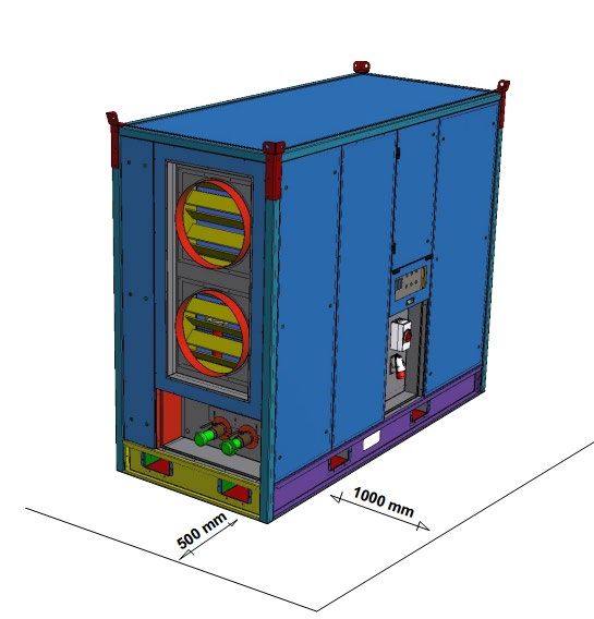
Contents

Contents ...................................................................................................................................................... 2
1.     Introduction .......................................................................................................................................... 5
2.     Warranty .............................................................................................................................................. 6
3.     Description of the Aqua Cool ................................................................................................................ 7
     3.1.     Design types................................................................................................................................. 7
     3.2.     Aqua Cool system principle........................................................................................................... 7
4.     General maintenance / securing ........................................................................................................... 8
     4.1.     Maintenance of the Aqua Cool ...................................................................................................... 8
5.     Description of the components ............................................................................................................. 9
     5.1.     Brief description of the cabinet layout. ........................................................................................... 9
     5.2.     (Air control) dampers .................................................................................................................... 9
     5.3.     Filter ............................................................................................................................................. 9
       5.3.1.         Filter maintenance ................................................................................................................ 9
     5.4.     Cooling battery ........................................................................................................................... 10
       5.4.1.         Maintenance 5.4 & 5.5 ........................................................................................................ 10
     5.5.     Drip tray...................................................................................................................................... 10
       5.5.1.         Drip tray maintenance ......................................................................................................... 10
     5.6.     Droplet eliminator/separator ........................................................................................................ 10
       5.6.1.         Droplet eliminator maintenance ........................................................................................... 10
     5.7.     Siphon ........................................................................................................................................ 11
       5.7.1.         Siphon maintenance ........................................................................................................... 11
     5.8.     Fan ............................................................................................................................................. 11
       5.8.1.         Fan maintenance ................................................................................................................ 12
     5.9.     Housing ...................................................................................................................................... 12
       5.9.1.         Maintenance of housing ...................................................................................................... 12
     5.10.        Control panel .......................................................................................................................... 12
       5.10.1.        Control panel maintenance.................................................................................................. 13
     5.11.        Switch panel ........................................................................................................................... 14
       5.11.1.        Maintenance of electrical equipment and switches .............................................................. 14
6.     Maintenance schedule for operating personnel + qualified personnel .................................................. 15
     6.1.     Damaged or missing pictograms ................................................................................................. 16
7.     Control Technology ............................................................................................................................ 17
     7.1.     Air inlet temperature sensor: ....................................................................................................... 17
     7.2.     Supply air temperature (internal/external) sensor: ....................................................................... 17
     7.3.     Fluid supply / return temperature sensor: .................................................................................... 17
     7.4.     Dual position switch (start/stop):.................................................................................................. 17

Version 5.1_2021 (6 July 2021)                                                                                                                  2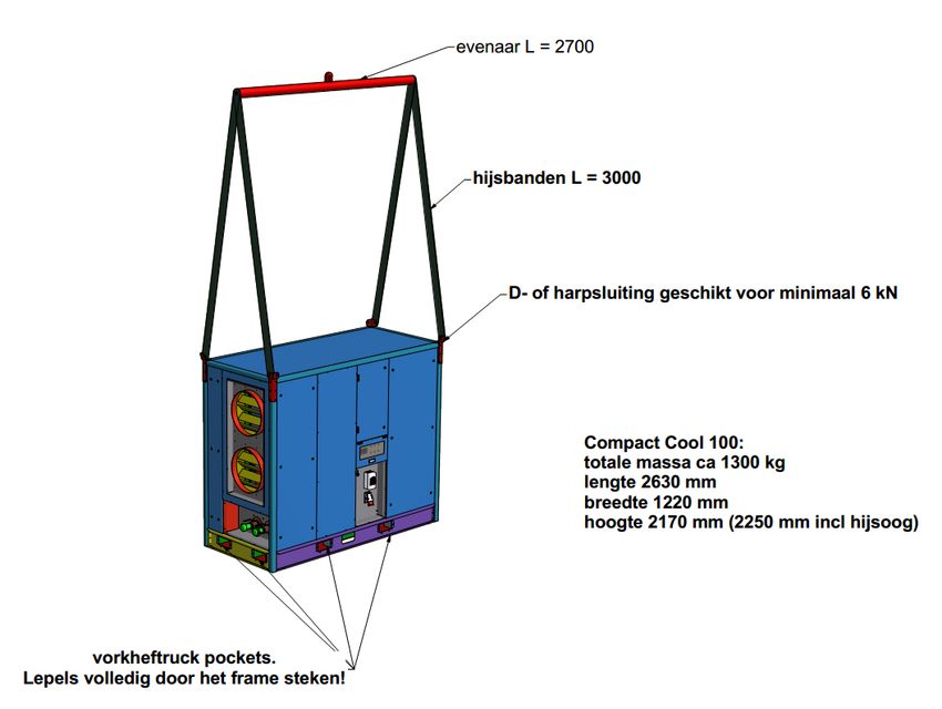
7.5.      Control panel: ............................................................................................................................. 17
     7.6.      Fans: .......................................................................................................................................... 17
     7.7.      Three-way valve: ........................................................................................................................ 17
     7.8.      Defrosting cycle: ......................................................................................................................... 18
     7.9.      tERA Portal:................................................................................................................................ 18
     7.10.         Control Technology error messages:....................................................................................... 18
       7.10.1.        Dirty filter message | not urgent: .......................................................................................... 18
       7.10.2.        Error message: ................................................................................................................... 18
       7.10.3.        Status message: ................................................................................................................. 18
       7.10.4.        Defrosting cycle active: ....................................................................................................... 19
8.     Set-up and installation ........................................................................................................................ 19
     8.1.      Preparations ............................................................................................................................... 19
     8.2.      Delivery and transport ................................................................................................................. 19
       8.2.1.         Vertical transport ................................................................................................................. 19
       8.2.2.         Horizontal transport ............................................................................................................. 20
     8.3.      Temporary storage ..................................................................................................................... 20
     8.4.      Final placement .......................................................................................................................... 21
     8.5.      Installation .................................................................................................................................. 21
     8.6.      Commissioning ........................................................................................................................... 22
     8.7.      Pre-commissioning check ........................................................................................................... 22
9.     Starting .............................................................................................................................................. 23
     9.1.      Decommissioning ....................................................................................................................... 23
10.         Safety............................................................................................................................................. 24
     10.1.         General safety instructions ...................................................................................................... 24
     10.2.         Statutory requirements ............................................................................................................ 24
     10.3.         Safety measures ..................................................................................................................... 24
11.         Display instruction .......................................................................................................................... 26
     11.1.         Graphical operating display .................................................................................................... 26
     11.2.         Display and operating buttons ................................................................................................. 26
     11.3.         P&ID diagram ......................................................................................................................... 28
     11.4.         IO list C.PCOe Mini ................................................................................................................. 29
     11.5.         User interface with display ...................................................................................................... 30
       11.5.1.        Function keys...................................................................................................................... 30
       11.5.2.        Adjusting the contrast.......................................................................................................... 30
       11.5.3.        Alarm messages ................................................................................................................. 30
     11.6.         Selection of menus ................................................................................................................. 31
     11.7.         Main menu and start-up .......................................................................................................... 32
     11.8.         Switching on/Switching off the unit .......................................................................................... 33

Version 5.1_2021 (6 July 2021)                                                                                                                3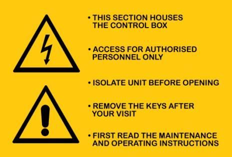
11.9.        Setpoint .................................................................................................................................. 34
     11.9.1.      Setpoint temperature........................................................................................................... 34
     11.9.2.      Setpoint speed .................................................................................................................... 34
     11.9.3.      Setpoint voltage .................................................................................................................. 34
     11.9.4.      Defrosting setting ................................................................................................................ 34
     11.9.5.      Manual mode ...................................................................................................................... 35
  11.10.       Information.............................................................................................................................. 36
  11.11.       Table of alarm messages ........................................................................................................ 38
  11.12.       Other functions ....................................................................................................................... 40
     11.12.1.         Indicator lights connected to digital output ....................................................................... 40
     11.12.2.         Supply air sensor - Automatic selection ........................................................................... 40
  11.13.       Menu settings  ........................................................................................... 40
     11.13.1.         Fan ................................................................................................................................. 40
     11.13.2.         Belimo............................................................................................................................. 40
     11.13.3.         Belimo............................................................................................................................. 41
     11.13.4.         Configuring the unit ......................................................................................................... 41
     11.13.5.         Alarm .............................................................................................................................. 41

Version 5.1_2021 (6 July 2021)                                                                                                            4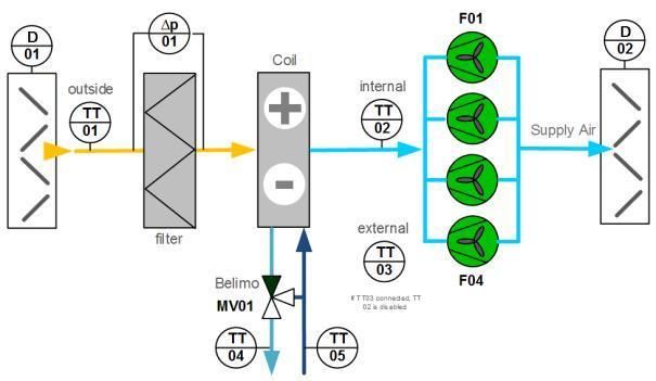
1.         Introduction

Read this manual carefully before putting the Aqua Cool into operation. Familiarise yourself with the operation
and handling of the machine and strictly follow the instructions provided.

This manual contains important information on the commissioning of your Aqua Cool. It also contains
instructions intended to protect you from possible accidents when using the unit and to prevent damage to the
unit. In addition, information regarding the maintenance of the Aqua Cool is included in order to promote
trouble-free operation.

For clarity, important items are indicated in bold along with the text 'CAUTION'. These are important
instructions that protect you from danger or refer to the risk of damage to the unit. Please bear all these
comments in mind.

If you have any questions or would like further clarification on specific issues relating to the unit, please do not
hesitate to contact one of our team in the Repair & Maintenance department on +31(0)416-672 200.

The data published in this manual are based on the latest information. They may be subject to subsequent
amendments. OC Verhulst reserves the right to change the construction and/or design of our Aqua Cool
without prior notice at any time or to modify previously made deliveries accordingly.

The Aqua Cool comes in one version: Aqua Cool 100.

Version 5.1_2021 (6 July 2021)                                                                        5
2.         Warranty

The warranty on the Aqua Cool is subject to the general terms and conditions of the NVKL.

The warranty lapses immediately and automatically if:

    •   Service and maintenance are not carried out strictly in accordance with the instructions, repairs are
        not carried out by OC Verhulst personnel or are carried out without the prior written permission of OC
        Verhulst.

    •   Changes to the equipment have been made without the prior written permission of OC Verhulst.

    •   Settings and/or safeguards have been changed without the prior written permission of OC Verhulst.

    •   Non-original parts or refrigerants or lubricants other than those prescribed are used.

    •   The equipment has not been placed and/or connected in accordance with the placement and
        installation instructions.

    •   The equipment is used improperly, incorrectly, negligently or not in accordance with its type and/or
        intended purpose.

In the aforementioned cases, OC Verhulst is indemnified against any product liability claims. In case of a
warranty claim, the order number of the respective unit must always be provided.

Version 5.1_2021 (6 July 2021)                                                                   6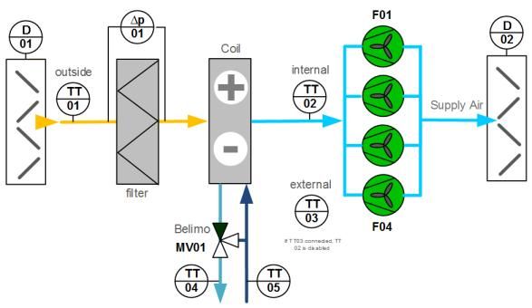
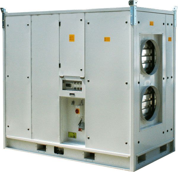
3.         Description of the Aqua Cool

The Aqua Cool is an air supply unit with a cold water coil. This unit was specially developed for supplying fresh
(outside) air into marquees and for temporary cooling in laboratories, for example. The Aqua Cool uses an
external cooling unit. The Aqua Cool converts the cold water into fresh, cool air.

The Aqua Cool can be used in environments up to 50°C.

The Aqua Cool has primarily cold water connections, but can also be equipped with hot water connections for
defrosting the cooling battery, for example. The Aqua Cool can be connected with an electric plug.

 Aqua Cool 100            16A       3P

    3.1.     Design types

The Aqua Cool 100 has a nominal output of 100 kW, maximum cooling capacity at 12,500 m3/h and is suitable
for both indoor and outdoor installation.

    3.2.     Aqua Cool system principle

 Aqua Cool 100
 D01                                                   Outside air inlet damper (manually operated)
 TT01                                                  Outside air inlet temperature
 ΔP                                                    Delta - P dirty filter switch
 Filter                                                Filter
 Coil                                                  Battery
 MV01                                                  Belimo 3-way valve
 TT04                                                  Return water temperature
 TT05                                                  Supply water temperature
 TT02                                                  Supply air temperature (internal)
 TT03                                                  Supply air temperature (external)
 F01 & F02                                             Fans 2 pcs (Aqua Cool 100)
 D02                                                   Supply air damper (manually operated)

Version 5.1_2021 (6 July 2021)                                                                     7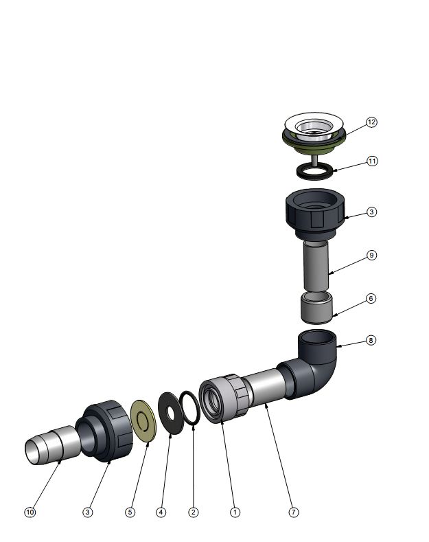
4.         General maintenance / securing

A warning label is attached to your Aqua Cool stating: "secure unit before opening". This means that before
opening the unit for service or maintenance work, switch off the unit using the main switch and lock the main
switch in the "off" position using a padlock. In this way you can avoid a dangerous situation during the
maintenance, should the unit be switched back on. Switching off and locking the main switch prevents this kind
of risk.

    4.1.     Maintenance of the Aqua Cool

Regular and careful maintenance of your Aqua Cool is essential for long-term, efficient and trouble-free
operation. A number of maintenance tasks can be caried out by the operating personel, see chapter 6.
Maintenance must be carried out by authorised and qualified personnel, see chapter 6. For maintenance, you
can use the service organisation of OC Verhulst, which offers you a maintenance contract for this. If you notice
any defects and/or deviations, please report this to our service organisation immediately. When reporting, it is
important to mention the order number of the unit (this number is indicated on the model plate of the unit). If
necessary, consult the wiring diagram during the inspection work.

The inspection schedules in these operating instructions have been compiled as a guideline for maintenance
work. OC Verhulst does not guarantee the completeness of this information and can therefore not accept
liability for any inaccuracies!

! CAUTION:
      The main switch of the unit must be switched off and locked at all times when handling or
      working on the unit!

! CAUTION:
      If a unit is installed on a roof, the effect of gusts of wind must be taken into account when
      opening and closing service doors.

Version 5.1_2021 (6 July 2021)                                                                    8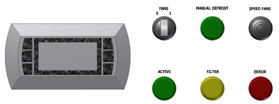
5.         Description of the components

    5.1.        Brief description of the cabinet layout.

Seen from the front to the back in the direction of airflow.
   - Housing with 2 holes (500 mm)
           o External air intake connection
           o Water-side connection by means of Bauer coupling ball valve. (cold / hot water)
   - 2x air control dampers
   - Intake filter G4
   - Three-way cold water system
   - Cooling coil incl. defrosting heater
           o plastic drip tray
           o droplet eliminator
           o siphons
   - 2 fans
           o Directly driven with EC motors
           o Removable from the side
   - 2x air control dampers
   - Housing with 2x connections (500mm)
           o For attaching supply air hoses
   - Control panel (behind plastic, transparent panel)
           o Accessible from outside
   - Switch panel behind closed door (CE)
           o Can only be opened with special tools

The dampers of the Aqua Cool 100 are manually operated and can be locked. Electrical connection (16
ampere) Menneke plug, 5-pin without 0. In the following subchapters, all components are listed separately
and the required maintenance is indicated.

    5.2.        (Air control) dampers

The external air intake is equipped as standard with a volume control damper with manual operation and
locking device. The dampers in the air outlet are also manually operated with a locking device. The dampers
are standard contra-rotating dampers with aluminium housing, aluminium damper blades and plastic
maintenance-free actuator.

       5.2.1.   Damper maintenance
The volume control dampers must be checked regularly for proper functioning and wear.

    5.3.        Filter

The intake filter is a G4 filter consisting of pleated filter material with a metal frame. The filters are mounted
in a metal sliding profile.

           5.3.1.    Filter maintenance

The filters must be replaced when the specified final resistance is reached. A non-urgent fault message on
the display of the Aqua Cool indicates that the filters must be replaced. Replace the filters with new ones of
the same type, ensuring correct positioning and safe (working) conditions.

When changing the filters, you should also clean the filter section.

Check the existing pressure sensors for proper functioning.

! CAUTION:

Version 5.1_2021 (6 July 2021)                                                                        9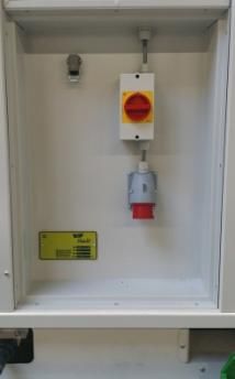
Be careful when changing filters. Chemical, biological or microbiological substances may
           have collected in the filter. These substances can be hazardous to health. They may also end
           up as residue at the bottom of the section. Always use personal protective equipment (safety
           glasses, gloves and P2 dust mask), never throw filters around, pack the dirty filters before
           moving them (in a box or bag). In very dry and dusty conditions, it may be desirable to
           moisten the filters slightly before removing them. Always dispose of used filters as chemical
           waste.

    5.4.        Cooling battery

A three-way cold water system is mounted on the front of the Aqua Cool. This system ensures that the
desired air supply conditions of the unit are achieved.

The three-way mixing system is suitable for water as a water/glycol mixture. This can be either hot or cold.
The flow rate can be regulated by means of valves via the unit control system.

CAUTION!
      A water/glycol mixture should always be used when there is a risk of frost.

The three-way mixing valve of the cooling battery is controlled by PLC.

           5.4.1.   Maintenance 5.4 & 5.5

The cooling coil front (inlet) unit can be reached by removing the filters. You should check the coil annually
for contaminants, and clean the coil if necessary using a high pressure water jet or compressed air, avoiding
damage to the fins. Repair any damage with a so-called 'Fin comb'.

When servicing coils, be aware of the hazards of the medium used; a neutral temperature is desired and the
medium must be sufficiently cooled. Even after switching off the heater (or cooler), the coil may remain hot
(or cold) for some time.

CAUTION!
      When disconnecting both the coil and the defrosting heater, the coil must be drained on the
      water side or stored frost-free.

    5.5.        Drip tray

The drip tray below the cooler collects the condensation water that runs off the cooler, including dirt.

           5.5.1.   Drip tray maintenance

Dirt, possibly including substances of a biological or microbiological nature, collects in the drip trays of
coolers. These substances may pose a threat to health. Therefore, be careful when cleaning these drip
trays. The drip tray under the cooler must be checked for dirt and cleaned if necessary.

    5.6.        Droplet eliminator/separator

The droplet eliminator is mounted at the end of the drip tray to keep condensation away from the cooling
element. The droplet eliminator guides this to the drip tray.

           5.6.1.   Droplet eliminator maintenance

Check the droplet eliminator for contamination every six months, dismantle and clean if necessary.

Version 5.1_2021 (6 July 2021)                                                                      10
5.7. Siphon
The draining of condensation (drip-tray) must be carried out using the siphon provided. This siphon serves
as a water shut-off to prevent possible unpleasant odours and to drain possible excess water from the drip
tray.
5.7.1. Siphon maintenance
The negative pressure siphon (silicone rubber non-return valve) must be cleaned. Please ensure correct
assembly. See picture.
Position number Description
1-2-3 3-piece coupling
4 diaphragm seat
5 Silicone diaphragm
6 Reducing ring 32-25
7 PVC pipe 32 L=40 / L=260
8 PVC elbow 32
9 PVC pipe 25 L=50
10 Hose coupling PVC 32 glue 30 hose
11 Flat ring (rubber)
12 Simplex plug 5/4"
5.8. Fan
The air flow through the heat exchangers is provided by directly driven plug fans with EC motors. The fans
are speed-controlled by means of a rotary knob located on the control panel.
The fans are controlled by the PLC and communicate via ModBus.
Because EC motors are used, there is no risk of the fans turning in the wrong direction. Please note that a
leakage current is present.
! CAUTION:
Version 5.1_2021 (6 July 2021) 11The main switch of the unit must be
switched off and locked at all times
when handling or working on the unit!
! CAUTION:
After switching off the supply voltage,
it will take some time before the fans
have come to a complete stop. Please
bear this in mind when opening the
service doors/hatches!
5.8.1. Fan maintenance
Clean the fan impeller if necessary. Make sure that the balancing weight on the impeller is not moved or
removed.
Check the impeller for imbalance. The imbalance is noticeable when the Aqua Cool vibrates noticeably on
the outside. In this case, remove the fan and have it rebalanced. It is also possible to have this done on site
by a specialised company.
Check wiring.
The motor is maintenance-free.
5.9. Housing
The housing of the Aqua Cool consists of double-walled (sandwich) panels made of Sendzimir-galvanised
sheet steel 1 mm thick, with an internal and external 100µ powder coating in RAL7035 as standard.
The housing has a wall thickness of approximately 50 mm. The insulation consists of expanded insulation
material and is fully bonded to the inner and outer sheets of the sandwich panel.
The housing has 2 connections for air inlet and 2 connections for air outlet. All connections are around 500
mm.
5.9.1. Maintenance of housing
The housing must be inspected periodically, both internally and externally, and if necessary cleaned with a
non-aggressive cleaning agent. Touch-up or reapply damaged coating.
Check all inspection doors/hatches for proper sealing and if necessary treat the rubbers against sticking and
replace if damaged. Check the roof for damage and leaks and touch it up if necessary.
5.10. Control panel
The control panel is located under the switch panel (via the door under the switch panel).
Version 5.1_2021 (6 July 2021) 12For more information on the control panel and how to operate it, see chapter 11(Display instructions).
5.10.1. Control panel maintenance
The control panel should only be cleaned periodically on the outside with a non-aggressive cleaning agent.
Inspect the panel and if necessary report any damage and have it repaired by OC Verhulst.
Version 5.1_2021 (6 July 2021) 135.11. Switch panel
The switch panel is fully compliant with NEN-EN-60204-1. On delivery of the Aqua Cool, the electrical
diagram is located in the logbook (inside the service door/hatch).
The electrical control is carried out by the control unit housed in the controller compartment.
Please refer to the operating instructions of the control system used in your unit (and, if applicable, the
electrical diagram) for details on how to operate and reset the various protection devices.
! CAUTION:
Work on the electrical system may only be carried out by trained and certified personnel.
5.11.1. Maintenance of electrical equipment and switches
Maintenance is mainly limited to removing dust and dirt at least twice a year and, if necessary, cleaning the
contacts. In addition, the functioning of the process control equipment must be checked periodically.
Version 5.1_2021 (6 July 2021) 146. Maintenance schedule for operating personnel + qualified
personnel
Number of inspections
Components to be checked on the Aqua Cool per year *
Air control dampers
Check the dampers for proper functioning and wear Regularly
Check the condition of the volume control damper (dirt, seals, actuator) 2
Filters
Check the pressure differential across the filters, replace the filters if necessary 2
Check the mounting of the filters (leakage) 2
Cooling elements (or heater)
Check elements for contamination, clean where necessary 1
Check the condition of the coil (dirt, leakage, corrosion, obstructions) 2
Check the condition of the drip tray (dirt, drain, leakage) and siphon 2
Check the condition of the heat exchanger (dirt, leakage, corrosion, obstructions) 1
Clean the heat exchanger with a soft brush 1
Check condition of drip tray (dirt, drain, leakage) and siphon, clean if necessary 1
Fans
Check the condition of the fans (dirt, corrosion, shaft clearance, imbalance) 1
Clean the ventilator fans and the drive if necessary 1
Check the set-up for good airflow (katabatic winds, blind spot, short circuit, intake of fumes) 1
Check the fastening bolts for tightness 1
Check electrical connections for tightness 1
Control panel / switch panel
Check that the controller compartment is clean and dry 2
Check the condition of the cables (worn, burned, damaged) 2
Check the condition of the insulation (dirt, moisture, damage) 2
Check that the controller compartment is clean and dry 1
Check the condition of the switches (dirt, corrosion) 1
Check the condition of the contacts (dirt, corrosion, burns) 1
Check all connections for tightness 1
Check the condition of the cable insulation (worn, burned, damaged) 1
Check the settings of the thermal protections 1
Check the condition of fuses (tightness, value) 1
General
Check the unit set-up (vibration dampers, foundation, is it level?) 1
Check the condition of the housing (tightness, dirt, corrosion) 1
Check the condition of the insulation 1
Check that all pictograms are still present 1
* or after each rental period
Maintenance by qualified personnel once a year
• Check the condition of the heat exchanger (dirt, leakage)
• Check the pressure differential across the filters, replace the filters if necessary
• Check the mounting of the filters (leakage)
• Check the condition of the fans (noise, dirt, temperature, corrosion)
• Check the amperage of the fans (amperage: see electrical diagram)
• Check the function and setting of the "dirty filter signal" protective device
• Check the protective functions included in the control unit (see control unit operating instructions for
these)
Version 5.1_2021 (6 July 2021) 15! CAUTION:
When checking the functioning of protections by disconnecting connections on the terminal
strip, make sure that they are reconnected in the original manner, and that all connections are
firm.
6.1. Damaged or missing pictograms
The Aqua Cool is equipped with the following pictograms as standard:
- Control panel location
- Watch out for rotating parts
- Secure before opening
- OC Verhulst model plate
High Voltage Rotating Parts
Missing or damaged pictograms should be (re)affixed as follows.
When affixing pictograms, proceed as follows:
• Clean the surface with a non-aggressive degreaser.
• Heat this section with a hairdryer until it is hand-warm.
• Remove the protective sheet and stick the pictogram in the correct position.
• Press the pictogram firmly and make sure that no air bubbles form underneath.
After application, allow the adhesive layer to cure for 24 hours before bringing the pictogram into contact with
water and/or cleaning agents.
Version 5.1_2021 (6 July 2021) 167. Control Technology
Components for control technology are integrated into the Aqua Cool. The control strategy is determined by
selecting cooling or heating via the software.
For control technology, please refer to the user manual supplied with the product, which can also be found on
our website www.oc-verhulst.nl.
In OC Verhulst units that are frequency-controlled or equipped with EC technology, residual current devices,
neutral grounding can be used as extra protection, provided that local safety regulations are observed. A
grounding fault can cause a direct current in the discharge current. Do not use type A residual current devices
as they are not suitable for DC leakage currents. If residual current devices are used, they must comply with
local regulations. The residual current devices used must be suitable for protecting a unit with a direct current
(DC) in the grounding leakage flow (3-phase DC bridge). In addition, they must be suitable for a high leakage
current and for a short discharge current when switched on.
7.1. Air inlet temperature sensor:
Temperature sensor is mounted in the space between outdoor air inlet dampers and filters.
7.2. Supply air temperature (internal/external) sensor:
The internal temperature sensor is mounted in the space between the fans and supply dampers. It is also
possible to connect an external temperature sensor via a connection outside the cabinet. When this is
connected, the control strategy automatically changes to external temperature sensor.
7.3. Fluid supply / return temperature sensor:
For flow control, a temperature sensor is mounted on the supply and return lines of the coil.
7.4. Dual position switch (start/stop):
The fans and the three-way valve can be switched on or off via the dual position switch. Optionally, it is
possible to control the unit with a time schedule (see defrosting cycle).
7.5. Control panel:
Everything can be set via the control panel. The main screen contains the most important data. Fan speed,
three-way valve control and temperature setpoint.
7.6. Fans:
The fans are controlled via a potentiometer (0-100%) and a dual position switch stop /start). The controller
translates this to the EC fan via ModBus and is controlled by it.
7.7. Three-way valve:
The valve is controlled via 0-10V. The control is based on a PI control with setpoint and supply air
temperature or room temperature.
Version 5.1_2021 (6 July 2021) 177.8. Defrosting cycle:
Defrosting cycle is started manually via a push button. The first time the button is pressed, the defrosting
cycle of 10 minutes starts. After each press, 10 minutes are added. The time can be read from the display.
Pressing the push button for 5 seconds resets the defrosting cycle and restarts the standard control strategy.
During the defrosting cycle, the fan is reduced to a percentage of the speed set in the controller.
The defrosting cycle can also be set as a time schedule. Via the display, an ending time and eight different
start times can be set. The unit will then switch on at the set time and run for the set duration. It switches off
automatically (after the duration) and on again at the next set time.
7.9. tERA Portal:
A tERA portal can be connected to the Carel controller. The tERA portal is a GPRS box that allows you to
read and operate everything remotely. It is also possible to log (graphs, tables).
7.10. Control Technology error messages:
The display has the possibility to switch on three lights: green, orange and red. The various combinations are
error messages or confirmation of being in operation.
On On Off Off Off
Off On On Off Off
Off Off On On Off
Unit is on. Unit is on. Unit is off. Unit is off. Unit is switched
off.
Dirty filter & Urgent fault.
Works according Non-urgent dirty Urgent fault.
to settings. filter message.
7.10.1. Dirty filter message | not urgent:
Delta-P switch over the filter. When pressure drop is too high, the switch will engage and illuminate an
orange light called 'Filter'.
7.10.2. Error message:
All faults will be displayed via a red light called 'error'. These errors can be reset manually, automatically or
remotely (if a tERA box is present).
7.10.3. Status message:
When the dual position start/stop switch is on and there is no urgent fault, it will be active. When there is an
urgent fault, the error light will be active and the status off (unit will switch off). In case of a non-urgent fault,
the fault and status message will be active and the unit will continue to run.
Version 5.1_2021 (6 July 2021) 187.10.4. Defrosting cycle active:
Light active when defrosting cycle is active. Also readable from the display of the Carel controller (countdown
timer).
8. Set-up and installation
! CAUTION:
This chapter contains important instructions on how to safely install your Aqua Cool!
8.1. Preparations
The following preparations are important for setting up the Aqua Cool:
- The unit is designed for both indoor and outdoor installation.
- The Aqua Cool should be placed on a stable surface.
- The set-up must be designed in such a way that there is sufficient space around the unit for
inspection and service work. The need to work safely must be borne in mind. This requires a
clearance of at least 1 metre on the inspection side. Moreover, free space is necessary for
unimpeded air supply and extraction. Attention must be paid to prevent an air short circuit between
the air injection and intake. The intake of fresh outside air must be taken into account (no exhaust
fans or other exhaust openings in the immediate vicinity of the air intake opening).
- The foundation must be such that the unit can be set up level, with the load sufficiently supported,
and vibration transmission minimised.
Safety!
- Before the Aqua Cool can be put into operation, all inlet and outlet openings must be fitted with ducts
or grilles. All inspection doors / hatches must be closed. This is to prevent physical injury.
! CAUTION:
To ensure that the unit functions properly, it must be set up completely level (height should
be compensated with shims under the unit or vibration dampers).
If you have any questions or doubts about the set-up options, please contact OC Verhulst.
Information on dimensions and weights is given in the technical data mentioned above and on the scale
drawing of your unit.
8.2. Delivery and transport
We advise you to check your Aqua Cool immediately upon delivery by OC Verhulst for transport damage.
Report any transport damage immediately to the carrier and within 24 hours to OC Verhulst. If transport
damage is not reported immediately, all warranty claims become null and void.
Also check that the delivery is complete (see the packing list) and that the necessary documentation is
present (in the control compartment).
8.2.1. Vertical transport
When transporting to the installation site, please ensure that the transport and lifting instructions shown in
the drawings below are followed. The unit must be moved using appropriate lifting gear.
When lifting the air handling unit, the lifting eyes at the top of the unit must be used. The hoisting strap must
be attached to the crane hook with a bow shackle (4 pcs M16). Please note the stated weight!
Version 5.1_2021 (6 July 2021) 19Equator (arm) L = 2700
Hoisting belt L = 3000
Harp shackle suitable for at least 6 kN
Aqua Cool 100:
Total mass ca. 1300 kg
Length 2630 mm
Width 1220 mm
Height 2170 mm (2250 mm. including lifting eyes)
Forklift pockets.
Insert the spoons completely through the frame.
8.2.2. Horizontal transport
If the crane hooks are not used, use the fittings in the frame (so-called hoisting pockets). Use forklift prongs
with sufficient length. These should protrude through the frame. The use of chains is not recommended.
! CAUTION:
During transport by OC Verhulst, all openings as well as other connections are covered.
Leave this sealing intact for as long as possible to prevent dirt and moisture from entering
the unit.
All valves must be closed during transport by the rental company.
8.3. Temporary storage
If the Aqua Cool cannot be set up immediately, all the medium and air openings must be temporarily closed
and all valves closed. If the Aqua Cool is taken out of operation for a longer period of time, the following
points should be noted:
• The unit must be switched off properly (see chapter 9.1.
• All dampers and valves must be closed.
• If a glycol mixture is used, it must be drained off. This also applies to the cooler and defrosting
heater.
• It is possible to stack the units on top of each other. CAUTION maximum of 2 on top of each
other!
Version 5.1_2021 (6 July 2021) 208.4. Final placement
When deciding on the location for the Aqua Cool, sufficient
space around the air handling unit should be taken into
account to allow for operation and the work to be carried out.
At least 1 metre should be available at the front. The unit must
be able to suck in and extract air freely.
Ensure good and safe accessibility, and where necessary,
provide railings and/or fall protection, e.g. when positioning
the unit close to the roof edge.
The Aqua Cool should be set up level and placed flush with
the ground frame on a stable surface so that the inspection
panels / doors can be opened and closed easily.
8.5. Installation
Electrics connection, see photo.
Main switch 40A
5-pin plug 32A
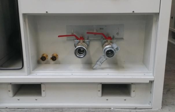
Version 5.1_2021 (6 July 2021) 21Water connection, see photo:
Not available on the Not available on the
Aqua Cool Aqua Cool Supply water Return water
8.6. Commissioning
The installation of the Aqua Cool must comply with the general and locally applicable building, safety and
installation regulations of the local authorities and the electricity and water companies.
Connect the power supply to the wall socket as shown in the electrical diagram supplied. Connect the unit on
the water side using the Bauer couplings. The supply is the female, the return is the male.
8.7. Pre-commissioning check
- Check the points mentioned in chapter 8.
- If present, check the water circuit and especially all connections for leaks.
- Check whether there is sufficient water pressure in the hydraulic system.
- Check that air inlet and outlet can take place unhindered.
- Check that the correct supply voltage is present.
- Check that the unit is still level even after the ducts and any pipes have been connected and the
system has been filled.
Version 5.1_2021 (6 July 2021) 229. Starting
Before starting the unit, you can also view the external Quickstart.
The release of the unit comes from the clock programme and/or from the switch on the control panel. If the
controller does not present any limiting actions, the unit will start.
The following conditions must be fulfilled before starting the Aqua Cool:
If present, the hot water/cold water circuit must be adequately filled. Check whether there is air in the
water system and bleed if necessary.
If all of the above conditions are met, you can start your Aqua Cool:
! CAUTION:
Do not start the fans until the ducts and supply hoses and inlet covers (grilles) have been
correctly fitted, as any dirt sucked in will leave the fans at high speed!
Refer to the electrical diagram and the operating instructions of the control system to familiarise yourself with
the control of the unit.
Depending on the prevailing conditions, the unit will start in the desired operating mode.
When checking the operating conditions, reference can also be made to the values indicated on the
electrical diagram.
9.1. Decommissioning
To decommission your Aqua Cool, carry out the following actions (see also chapter 8.3).
- Remove the start command from the control panel (see the electrical diagram).
- If there is a risk of freezing, OC Verhulst recommends that you drain the water circuit (if present) and
blow it dry using compressed air.
Version 5.1_2021 (6 July 2021) 2310. Safety
Due to the nature of the processes that takes place in it, your Aqua Cool represents various risks, including
those of a mechanical, electrical and chemical nature. This section lists the various risks and measures
taken and provides instructions for handling your unit safely. Please read this chapter carefully and
familiarise yourself with the safety aspects before performing any actions or allowing them to take place.
The safety information in these operating instructions has been compiled as a guide for handling the
unit safely. OC Verhulst does not guarantee the completeness of this information and can therefore
not accept liability for any inaccuracies.
Although the Aqua Cool is equipped with extensive safety and protection features, we strongly advise you
to exercise caution when operating the unit. When working on the unit with open service doors while it is
running, the use of hearing protection is recommended. Parts of the unit are under positive pressure when
the fans are in operation, while other parts are under negative pressure. Bear this in mind when opening and
closing the service doors.
10.1. General safety instructions
- Always observe the safety regulations, warnings, notes and instructions in this manual.
- Failure to follow the safety regulations, warnings, notes and instructions may lead to personal injury
or damage to the Aqua Cool.
- The installation of the Aqua Cool must be carried out in accordance with the general and local
building, safety and installation regulations of the local authorities, as well as the electricity and water
supply companies.
- Only an approved installation engineer may install, connect, commission and service the Aqua Cool.
- Instructions for maintenance, cleaning and changing the filters must be strictly followed
- Modification of the Aqua Cool is not permitted.
- It is recommended that a maintenance contract be taken out so that the Aqua Cool can be checked
regularly.
- Keep the operating instructions near the Aqua Cool for the duration of its service life.
Your Aqua Cool is fitted with a main switch that also serves as an emergency stop button. The switch
therefore has a red control on a yellow background. Switch off the unit by turning the main switch to the off
position in case of emergency.
10.2. Statutory requirements
The Aqua Cool complies with the following European Directives:
- EC Directive 2006/42/EC (Machinery Directive).
- EC Directive 2006/95/EC (Low Voltage Directive).
- EC Directive 2004/108/EC (EMC Directive).
- EC Directive 2014/68/EU (Pressure Equipment Directive).
and is therefore CE-marked (for information see EC Declaration of Conformity, specific version supplied with
the unit.
The installation must comply with all applicable regulations.
10.3. Safety measures
The Aqua Cool is designed to be operated with all service doors and panels fully closed. The housing of the
units itself also protects the user from the risks associated with the components inside:
Version 5.1_2021 (6 July 2021) 24- Rotating parts with risk of catching or trapping loose clothing or limbs. These include fans, motors
and drives, as well as volume control dampers and actuators. Take the effect of fan inertia into
account: a fan will run for some time after being switched off. A fan can also be made to rotate as a
result of air movement. Maintenance and service work requires sufficient lighting from the
surroundings, such as an additional light source built into the unit or a flexible light source such as an
inspection lamp.
- Electrical power supply for various components in the unit.
- Electric switch compartment
- Hot pipes and surfaces.
- Sharp edges and surfaces.
To ensure that only authorised persons have access to the interior of the unit, all service doors and panels
have locks that can only be opened with a special key. Two keys are supplied with each unit.
Use the locks as intended, and close all service doors and panels completely after opening them. Make sure
that the keys are only available to authorised persons. Do not leave the keys in a lock or near the Aqua
Cool unit. The opening of service doors or panels of a unit in operation by unauthorised and/or unqualified
persons poses a life-threatening danger!
The unit is intended to be operated only with all air ducts, air intake and air injectors fitted correctly. Do not
look into the ventilation hood of an operating unit, as the airflow can blow out (dust) particles forcefully (risk
of damaging the eyes).
The Aqua Cool is designed for a maximum ambient temperature of 50ºC (both in storage and in use).
The safety of installers and operating personnel is ensured by the following devices:
• The main switch can be locked in the zero position (off).
• All live parts are designed to be touch-safe in order to prevent accidents during maintenance work.
It is very important that the protections fitted by OC Verhulst remain in place or that - if removal for
maintenance is required - the original protections are refitted in the original manner. A number of
parts carrying a safe voltage (11. Display instruction
The following explains the operation of the COMPACTrs1.0.
11.1. Graphical operating display
The control unit contains 6 operating keys and a graphical, LED-lit display. It offers the possibility of an alarm
log and four interfaces.
11.2. Display and operating buttons
In normal condition, the display shows an overview of the current time, date and day. In addition, the
following data are visible:
Version 5.1_2021 (6 July 2021) 26A Current selected sensor (ext (external) or int (internal)) B Current supply temperature C Current air inlet (intake) temperature D Fan speed setting by analogue input E Counter for defrosting activated by push button F Current status Fan F01 G Current status Fan F02 H Current status Fan F03 (not applicable to Aqua Cool 100) I Current status Fan F04 (not applicable to Aqua Cool 100) J Current status Belimo K Current unit mode: Heating, Cooling, Defrosting L Current status of the unit: Off / On / On by task scheduler In the external Quickstart you will find a brief user explanation. In the following chapters you will find the detailed description, including the menus that are only accessible with a password (see 11.6). Version 5.1_2021 (6 July 2021) 27
11.3.   P&ID diagram

 D01                         Outside air suction damper 2x (manually operated)
 TT01                        Outside air inlet (intake) temperature
 ΔP                          Delta - P dirty filter switch
 Filter                      Filter
 Coil                        Battery
 MV01                        Belimo 3-way valve
 TT04                        Return water temperature
 TT05                        Supply water temperature
 TT02                        Supply air temperature (internal)
 TT03                        Supply air temperature (external)
 F01 & F02                   Fans 2 pcs (Aqua Cool 100)
 D02                         Supply air damper 2x (manually operated)

Version 5.1_2021 (6 July 2021)                                                   28
11.4.   IO list C.PCOe Mini

DIGITAL output
              Description                             Remark
 NO1          Defrosting mechanism
 NO2          Dirty filter indicator light
 NO3          Error light
 NO4          Status light
 NO5          Reserve

DIGITAL input
              Description                             Remark
 ID1          Start/stop switch
 ID2          Dirty filter                            ∆p 01
 U7           Start defrosting

ANALOGUE output
              Description                             Remark
 Y1 (0-10V)   Belimo 3-way valve                      MV01
 Y2 (0-10V)   Setpoint output

ANALOGUE input
              Description                             Remark
 U1           Air inlet (intake) temperature sensor   TT01 / NTC10K
 U2           Supply air temperature (internal)       TT02 / NTC10K
 U3           Supply air temperature (external)       TT03 / NTC10K
 U4           Supply temperature element              TT04 / NTC10K
 U5           Drain temperature element               TT05 / NTC10K
 U6           External speed controller F01-F04       0-10V
 U7           See digital input
 U8           Reserve
 U9           Reserve
 U10          Reserve

Communication
              Description                             Remark
 BMS2         Connection Terra                        Modbus RTU Slave 19200, 8, 2, N
 FB2          EBM Papst fan connection                Modbus RTU Master 19200, 8,1, Equal
 Fan F01      Address 2
 Fan F02      Address 3
 Fan F03      Address 4                               Not applicable to Aqua Cool 100
 Fan F04      Address 5                               Not applicable to Aqua Cool 100

Version 5.1_2021 (6 July 2021)                                                              29
11.5. User interface with display
The controller is equipped with an interface with display.
The user interface consists of an easy-to-read alphanumeric LCD display equipped with LED-lit function
keys. The screens shown on the user interface display the data provided by the I/O module of the controller.
The controller is operated by means of a 6-button menu structure and provides the operator with an alarm
log plus four different menu levels: Information, Operation, Service and Factory. These menus allow the user
to easily view, control and configure the operational parameters for the unit.
11.5.1. Function keys
11.5.2. Adjusting the contrast
Hold down the (Alarm) and (Prg) buttons, then use the Up/Down arrow to adjust the contrast.
11.5.3. Alarm messages
All alarm messages work as follows:
• When an alarm message is triggered, the red LED flashes and the buzzer is activated (if present);
the output relay is activated
• When the (Alarm) button is pressed, the red LED lights up constantly, the buzzer is switched off and
the alarm screen is displayed
Version 5.1_2021 (6 July 2021) 30• If there is more than one active alarm message, you can scroll between them using the (Up) (Down)
key.
• Pressing the (Alarm) button again for at least 3 seconds will manually acknowledge the alarm
messages and clear them from the display unless other messages are active (they will be stored in
the logbook).
11.6. Selection of menus
The controller provides the user with menus that can be selected for displaying operating data and entering
setpoint values for the system. These menus can be accessed from a browsable main menu by pressing the
programming key (Prg).
The default password for all levels is provided by email upon delivery to the hire company. This password
must not be given to the hirer. The hire company is responsible for this.
Version 5.1_2021 (6 July 2021) 3111.7. Main menu and start-up
After the controller is switched on, the following procedure is shown in one work flow:
Initialising and booting up the CPU (wait 15
seconds)
After initialisation, the start screen is displayed:
A Current selected sensor (ext (external) or int (internal))
B Current supply temperature
C Current air inlet (intake) temperature
D Fan speed setting by analogue input
E Counter for defrosting activated by push button
F Current status Fan F01
G Current status Fan F02
H Not applicable to Aqua Cool 100
I Not applicable to Aqua Cool 100
J Current status Belimo
K Current unit mode: Heating, Cooling, Defrosting
L Current status of the unit: Off / On / On by task scheduler
When you press Quick Menu (M) you can access: On/Off, setpoints and system information.
Version 5.1_2021 (6 July 2021) 3211.8. Switching on/Switching off the unit In this menu, the user can switch on the unit. The corresponding menu screen is as follows: The unit can now be used when the following conditions are met: Either the external On/Off is set or the task scheduler must be activated. The task scheduler can be opened by pressing in the On/Off shortcut menu: Version 5.1_2021 (6 July 2021) 33
11.9.    Setpoint

        11.9.1.   Setpoint temperature

Set the temperature for controlling the Belimo valve based on the PID controller. The controlling sensor is
either the internal or - if connected - the external temperature sensor for the supply air. The setpoint screen
is as follows:

Note: Depending on the setting in unit configuration (cooling or heating), this setpoint applies to the
controller. For example, if the supply temperature is 20°C, the unit is in heating mode and the setting is 13°C.
This is not controlled by the Belimo.

        11.9.2.   Setpoint speed

The setpoint for the speed of the fans depends on the analogue input. 0V = 0% and 10V = 100%. This
screen shows the current setpoint for the speed given by the analogue input:

        11.9.3.   Setpoint voltage

Enter this menu to set a 0-10V signal for the analogue output:

        11.9.4.   Defrosting setting

The defrosting cycle is started manually by means of a push button. After pressing the button, the digital
output is executed. When you press the start button for the first time, the defrosting cycle starts for a period
of 10 minutes. Each press of the button increases the defrosting time by 10 minutes. So if the defrost button
is pressed twice = 20 minutes, 3 times is 30 minutes etc. The time is visible on the display. If you keep the
button pressed for 5 seconds, the defrosting cycle stops. During the defrosting cycle, the fans gradually
return to a minimum flow rate of 50% (adjustable) when no power supply is connected to the defrosting
electrical circuit. When electrical defrosting is present, the fans are controlled at a fixed speed of 0%.

In addition, defrosting can be started daily by a task scheduler with a start and end time. Eight timings can be
set.

For example:
Defrosting speed setpoint: 10%

Version 5.1_2021 (6 July 2021)                                                                     34
You can also read