Handleiding N Anleitung D - Manual E Manuel F Manual S Smart BMS CL 12/100 - Victron Energy
←
→
Page content transcription
If your browser does not render page correctly, please read the page content below
Manual

                                  EN
                  Handleiding

                                  NL
                        Manuel

                                  FR
                      Anleitung

                                  DE
                        Manual
                                  SE

Smart BMS CL 12/100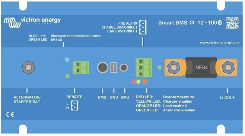
H

2

1. General Description

                                                                                     EN
A Smart BMS with Charge Current Limiter that protects the alternator
against overload
The Smart BMS CL is intended for use with Victron Smart LiFePo4 batteries
with M8 circular connectors. It supports up to 5 batteries in parallel (BTVs are

                                                                                     NL
simply daisy-chained).

Starter battery Protection
This function is similar to that of a Cyrix Battery Combiner or Argo FET Battery
Isolator. Current can flow to the LFP battery only if the input voltage (= voltage

                                                                                     FR
on the starter battery) exceeds 13V.
Additionaly, current cannot flow back from the LFP battery to the starter
battery, thus preventing eventual damage to the LFP battery due to excessive
discharge.

                                                                                     DE
Alternator and battery protection
The input current is electronically limited to approximately 80% of the fuse
rating. A 100A fuse, for example, will therefore limit the input current to
approximately 80A. (For fuse ratings and corresponding current limit please

                                                                                     SE
see table 1)
Choosing the right fuse will:
a. Protect the LFP battery against excessive charge current (important in case
of a low capacity LFP battery).
b. Protect the alternator against overload in case of a high capacity LFP
battery bank (most 12V alternators will overheat and fail if running at
maximum output during more than 5 minutes).

Li-ion battery protection
Excessive input voltage and transients are regulated down to a safe level.
The BMS will stop charging in case of cell over voltage or over temperature.
It has three outputs, similar to the miniBMS:
Load Disconnect output
The Load output is normally high and becomes free floating in case of
imminent cell under voltage (default 2,8V/cell, adjustable on the battery
between 2,6V and 2,8V per cell). Maximum current: 10mA. The Load output
can be used to control the remote on/off input of a Battery Protect, inverter,
DC-DC converter or other loads.
Pre-Alarm output
The pre-alarm output can be used as warning when the battery voltage is low
and it will trip shortly before the Load Disconnect output is disabled due to cell
under voltage.
The pre-alarm output may be used to drive a relay, LED or Buzzer. It can be
configured as continuous or intermittent signal.
The pre-alarm output is normally free floating and becomes high in case of
imminent cell under voltage (default 3,1V/cell, adjustable on the battery
between 2,85V and 3,15V per cell). Maximum current: 1A (not short circuit
protected)

                    1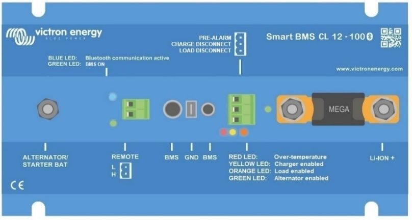
The minimum delay between pre-alarm and load disconnect is 30 seconds.
Charge disconnect output
The Charger output is normally high and becomes free floating in case of
imminent cell over voltage or over temperature. Maximum current: 10mA. The
Charger output is not suitable to power an inductive load such as a relay coil.
The Charger output can be used to control: The remote on/off of a charger, a
Cyrix-Li-Charge relay, a Cyrix-Li-ct Battery Combiner.
(Note: in some cases an interface cable will be needed, please see the
manual.)

A non-inverting or inverting on/off cable may be required, please consult the
appendix

Remote on/off input
The remote on/off input controls the charging via the alternator, while the BMS
functionality will remain active regardless of the remote on/off state.
The remote on/off can also be used as system on/off switch. Can be
conifugred via the VictronConnect.
The System on/off consists of two terminals: Remote L and Remote H.
A remote on/off switch or relay contact can be connected between L and H.
Alternatively, terminal H can be switched to battery plus, or terminal L can be
switched to battery minus.

LED indicators (from left to right)
 •   Green: Smart BMS CL 12V/100A is active
 •   Blue: blinking – Bluetooth broadcasting, ON – connection establised
 •   Red: Over-Temperature protection of the Current limiting 12V Smart
     BMS
 •   Yellow: Charge disconnect output is enabled
 •   Orange: Load disconnect output is enabled
 •   Green: Alternator Charging

2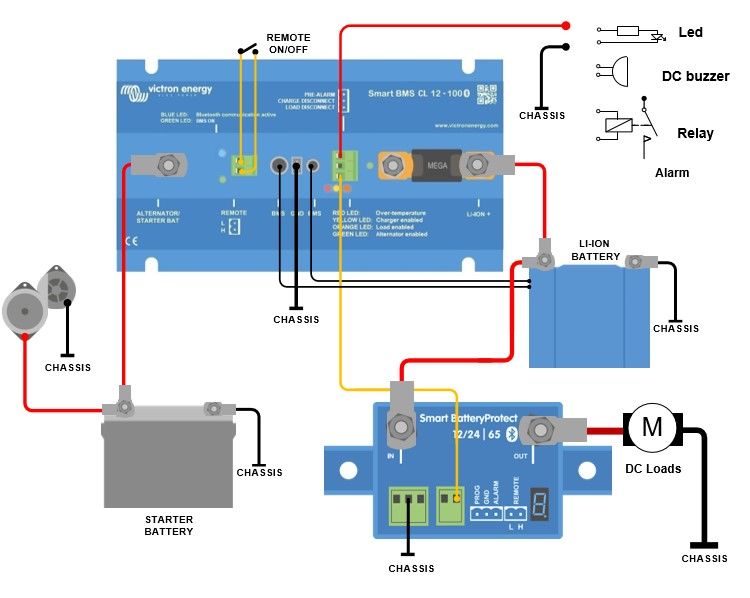
2. Safety instructions

                                                                                   EN
Installation must strictly follow the national safety regulations in compliance
with the enclosure, installation, creepage, clearance, casualty, markings and
segregation requirements of the end-use application. Installation must be
performed by qualified and trained installers only. Switch off the system and
check for hazardous voltages before altering any connection.

                                                                                   NL
1. Do not open the Lithium Ion Battery.
2. Do not discharge a new Lithium Ion Battery before it has been fully
   charged first.

                                                                                   FR
3. Charge only within the specified limits.
4. Do not mount the Lithium Ion Battery upside down.
5. Check if the Li-Ion battery has been damaged during transport.

                                                                                   DE
3. Installation instructions
1. Mount the BMS preferably on a vertical surface, for optimal cooling.

                                                                                   SE
2. Determine the rating of fuse (see figure and table 1). The fuse doubles as
   a shunt, thus the BMS CL will limit the input current according to the rating
   of this fuse. For fuse and corresponding current limit please see table 1.
   Choosing the right fuse will prevent overheating of the alternator and/or
   DC cabling.
3. Disconnect the cabling from the minus pole of the starter battery.
4. Pull off the REMOTE on/off connector to prevent unwanted switching of
   the BMS.
5. Install and connect the fuse and all electrical cabling, leave the minus
   poles of the Li-ion batteries and starter battery disconnected. Make sure
   that the M8 nuts of the fuse are properly tightened.
6. Daisy-chain the battery control cables between the Li-ion batteries and
   connect to the BMS.
7. Connect the GND cabling to the minus of Li-ion batteries and the starter
   battery.
8. Reinsert the REMOTE on/off connector on the BMS.

The BMS is now ready for use.

                    3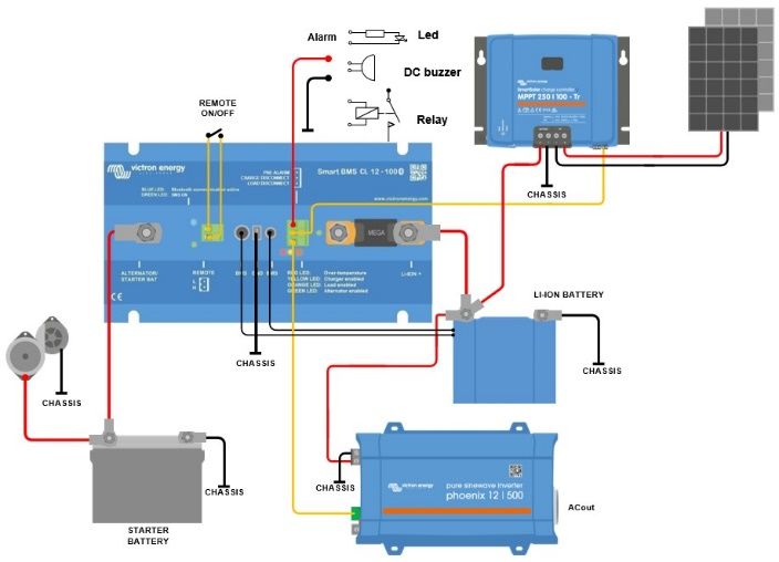
Table 1: charge current per fuse rating

     Fuse ratings       Max charge current
        125A                  100A
        100A                  90A
         80A                  60A
         60A                  50A
       2 x 30A                40A
       2 x 20A                25A
       2 x 15A                20A
       2 x 10A                12A
       2 x 7.5A                9A

4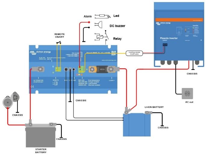
4. Things to consider

                                                                                        EN
4.1 Important warning
Li-ion batteries are expensive and can be damaged due to over discharge or
over charge.
Damage due to over discharge can occur if small loads (such as: alarm
systems, relays, standby current of certain loads, back current drain of battery

                                                                                        NL
chargers or charge regulators) slowly discharge the battery when the system
is not in use.
In case of any doubt about possible residual current draw, isolate the battery
by opening the battery switch, pulling the battery fuse(s) or disconnecting the

                                                                                        FR
battery plus when the system is not in use.

A residual discharge current is especially dangerous if the system has
been discharged completely and a low cell voltage shutdown has
occurred. After shutdown due to low cell voltage, a capacity reserve of

                                                                                        DE
approximately 1Ah per 100Ah battery capacity is left in the battery. The
battery will be damaged if the remaining capacity reserve is drawn from
the battery. A residual current of 10mA for example may damage a
200Ah battery if the system is left in discharged state during more than 8

                                                                                        SE
days.

4.2 DC loads with remote on/off terminals

DC loads must be switched off or disconnected in case of imminent cell under
voltage.
The Load Disconnect output of the Smart BMS CL 12-100 can be used for this
purpose.
The Load Disconnect is normally high (equal to battery voltage) and becomes
free floating (= open circuit) in case of imminent cell under voltage

DC loads with a remote on-off terminal that switches the load on when the
terminal is pulled high (to battery plus) and switches it off when the terminal is
left free floating can be controlled directly with the Load Disconnect output.
See appendix for a list of Victron products with this behavior.

For DC loads with a remote on/off terminal that switches the load on when the
terminal is pulled low (to battery minus) and switches it off when the terminal
is left free floating, the Inverting remote on-off cable can be used. See
appendix.

Note: please check the residual current of the load when in off state. After low cell
voltage shutdown a capacity reserve of approximately 1Ah per 100Ah battery
capacity is left in the battery. A residual current of 10mA for example may damage
a 200Ah battery if the system is left in discharged state during more than 8 days.

                     5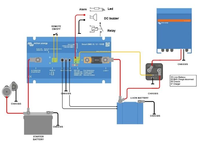
4.3 DC load: disconnecting the load with a BatteryProtect

A Battery Protect will disconnect the load when:
     -     input voltage (= battery voltage) has decreased below a preset
           value, or when
     -     the remote on/off terminal is pulled low.
The Smart BMS CL 12-100 can be used to control the remote on/off terminal
of a BatteryProtect.
Contrary to a Cyrix or contactor, a BatteryProtect can start a load with a large
input capacitor such as an inverter or a DC-DC converter.

4.4 Charging the LiFePO₄ battery with an additional battery charger

Battery charging must be reduced or stopped in case of imminent cell over
voltage or over temperature.

The Charge Disconnect output of the Smart BMS CL 12-100 can be used for
this purpose.
The Charge Disconnect is normally high (equal to battery voltage) and
switches to open circuit state in case of imminent cell over voltage.

Battery chargers with a remote on-off terminal that activates the charger when
the terminal is pulled high (to battery plus) and deactivates when the terminal
is left free floating can be controlled directly with the Charge Disconnect
output.
See appendix for a list of Victron products with this behavior.

Battery chargers with a remote terminal that activates the charger when the
terminal is pulled low (to battery minus) and deactivates when the terminal is
left free floating, the Inverting remote on-off cable can be used. See
appendix.

Alternatively, a Cyrix-Li-Charge can be used:
The Cyrix-Li-Charge is a unidirectional combiner that inserts in between a
battery charger and the LiFePO₄ battery. It will engage only when charge
voltage from a battery charger is present on its charge-side terminal. A control
terminal connects to the Charge Disconnect of the Current limiting 12V Smart
BMS.

4.5 Battery

In case of several batteries in parallel and/or series configuration, the two M8
circular connector cord sets of each battery should be connected in series
(daisy chained). Connect the two remaining cords to the BMS.

6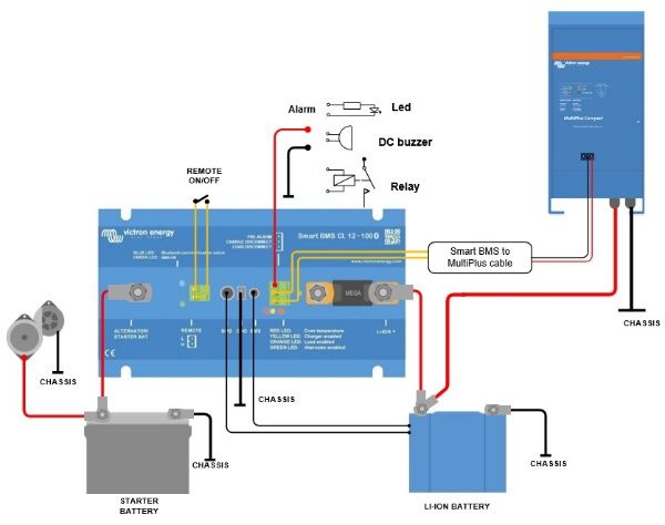
5. System examples
EN
NL
FR
DE
SE
Figure 1: Application example for a vehicle or boat, with on/off switch
between H and L
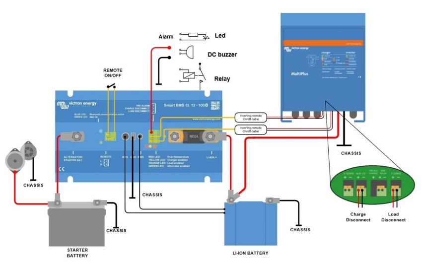
7Figure 2: Application example with a MPPT and a Phoenix inverter
Figure 3: Application example with a Phoenix VE.Bus Inverter rated at 3kVA
and more
8EN
NL
FR
DE
SE
Figure 4: Application example with a 3kVA Multi of a recent type that has
auxiliary inputs
96. Specifications
Smart BMS CL 12-200
Maximum continuous charge
100A (with 125A fuse)
current
Input voltage to start charging > 13V
Current consumption, remote on 16 mA (excluding Load output and Charge output current)
Current consumption, remote off 5 mA (BMS functionality still active)
Normally high (Vbat – 0.1V)
Load disconnect output Source current limit: 10mA (short circuit protected)
Sink current: 0A (output free floating)
Normally high (Vbat – 0.1V)
Charge disconnect output Source current limit: 10mA (short circuit protected)
Sink current: 0A (output free floating)
Normally free floating
Pe-alarm output High (Vbat) in case of alarm, max. 1A
(not short circuit proof)
Use modes of the system on/off:
a. ON when the L and H terminal are interconnected
System on/off:
b. ON when the L terminal is pulled to battery minus (V< 5V)
Remote L and Remote H
c. ON when the H terminal is high (V>3V)
d. OFF in all other conditions
GENERAL
Operating temperature range -40°C to +60°C
Humidity, maximum / average 100% / 95%
Protection, electronics IP65
DC power connection M8
DC connector battery minus Faston female, 6.3mm
ENCLOSURE
Weight 1,6kg
Dimensions (hxwxd) 65 x 120 x 224 mm
STANDARDS
Emission EN 61000-6-3, EN 55014-1
Immunity EN 61000-6-2, EN 61000-6-1, EN 55014-2
Automotive Directive ECE R10-5
10Appendix:
EN
1. Loads which can be controlled directly by the Load
Disconnect output of the BMS
Inverters:
All Phoenix inverters VE.Direct and Phoenix Inverters Smart:
NL
Connect the LOAD DISCONNECT to the left-hand terminal (H) of the 2-pole
connector
DC-DC converters:
FR
All Tr type DC-DC converters with remote on/off connector, and Orion 12/24-
20
Connect the LOAD DISCONNECT the right-hand terminal of the 2-pole
connector
DE
Battery Protect and Smart Battery Protect
Connect the LOAD DISCONNECT to terminal 2.1 (right hand terminal) for the
Battery Protect and H pin for the Smart Battery Protet of the 2-pole connector
Cyrix -Li-Load
SE
Connect the LOAD DISCONNECT to the control input
2. Loads for which an inverting remote on-off cable is
needed (article number ASS030550100 or -120)
All Phoenix VE.Bus inverters and VE.Bus Inverter Compact rated at 1200VA
or more.
3. Solar charge controllers which can be controlled
directly by the Charge Disconnect output
BlueSolar MPPT 150/70 and 150/80 CAN-bus
Connect the CHARGE DISCONNECT to the left-hand terminal of the 2-pole
connector (B+)
SmartSolar MPPT 150/45 and higher, 250/60 and higher
Connect the CHARGE DISCONNECT to the right-hand terminal (marked +)
or the left-hand terminal (marked H) of the 2-pole connector
4. Solar charge controllers for which a VE.Direct non
inverting remote on-off cable is needed
(article number ASS030550320)
All BlueSolar MPPT models, except the BlueSolar MPPT 150/70 and 150/80
CAN-bus
SmartSolar MPPT up to 150/35
115. Battery Chargers (note: no on-off cable needed when connecting the charger to the primary side of the BMS) Phoenix Smart IP43 Chargers Connect the CHARGE DISCONNECT to the left-hand terminal (H) of the 2- pole connector Skylla TG battery chargers Use a non inverting remote on-off cable. (article number ASS030550200) Skylla-i battery chargers Use a Skylla-i remote on-off cable (article number ASS030550400) Other battery chargers: Use a Cyrix-Li-Charge or connect the charger to the primary side of the BMS. 12
6. MultiPlus-II
The MultiPlus-II models can be controlled from the Load Disconnect and

                                                                                  EN
Charge Disconnect outputs by using the BMS CL 12-200 to MultiPlus cable
(article number ASS070200100) This cable must be wired to the remote on/off
connector of the MultiPlus-II (connect the black wire to the lower (-) terminal
and the red wire to the upper (+) remote on-off terminal). Both the Load
Disconnect and Charge Disconnect outputs of the BMS must be in ‘High’ state

                                                                                  NL
in order for the MultiPlus-II to operate. After shutdown due to low battery
voltage, run the alternator or use a battery charger on the primary side of the
BMS to reset the system. The MultiPlus-II will then switch on and start
charging (if connected to an AC power source).

                                                                                  FR
                                                                                  DE
                                                                                  SE

                 13
7. MultiPlus MultiPlus 3kVA or more For more info on how to configure the MultiPlus to work with the Smart BMS CL 12-100 please refer to the document on our website: https://www.victronenergy.com/upload/documents/Manual-Connecting-other- lithium-battery-systems-to-Multis-and-Quattros-EN.pdf The Load Disconnect and Charge Disconnect Outputs will be wired to the MultiPlus with two inverting remote on-off cables (article number ASS030550100) as shown in figure 4 above. MultiPlus 500VA – 1600VA & MultiPlus Compact 800VA – 2kVA These MultiPlus models can be controlled from the Load Disconnect and Charge Disconnect outputs by using the BMS CL 12-200 to MultiPlus cable (article number ASS070200100). This cable must be wired to the remote on/off connector of the MultiPlus (connect the black wire to the ON terminal and the red wire to the (+) terminal). Both the Load Disconnect and Charge Disconnect outputs of the BMS must be in ‘High’ state in order for the MultiPlus to operate. After shutdown due to low battery voltage, run the alternator or use a battery charger on the primary side of the BMS to reset the system. The MultiPlus will then switch on and start charging (if connected to an AC power source). 14
1. Algemene Beschrijving

                                                                               EN
Een Smart BMS met oplaadstroombeperker die de alternator beschermt
tegen overbelasting
De Smart BMS CL is bedoeld voor gebruik met Victron Smart LiFePo4
batterijen met M8 circulaire connectoren. Het ondersteunt tot 5 accu’s in

                                                                               NL
parallel (BTVs zijn eenvoudigweg in een keten).

Bescherming Startmotoraccu
Deze functie is gelijkaardig aan die van een Cyrix Accu-combiner of Argo FET
Batterij-scheidingsschakelaar. Stroom kan enkel naar de LFP-accu stromen

                                                                               FR
wanneer het invoervoltage (= voltage op de startmotorbatterij) 13V
overschrijdt.
Bovendien kan stroom kan niet terugstromen van de LFP-accu naar de
startmotoraccu, alzo mogelijke schade aan de LFP-accu vanwege overdadig

                                                                               DE
ontladen belettend.

Alternator en accubescherming
De invoerstroom is elektronisch beperkt tot ongeveer 80% van het
zekeringsgehalte. Een 100 A zekering bijvoorbeeld zal daarom de

                                                                               SE
invoerstroom beperken tot ongeveer 80 A. (Voor zekeringsgehaltes en
overeenstemmende stroombeperking, zie tabel 1)
Het kiezen van de juiste zekering zal:
a. De LFP-batterij beschermen tegen overdadige laadstroom (belangrijk bij
lage capaciteit LFP-accu).
b. De alternator beschermen tegen overbelasting bij een hoge capaciteit LFP-
accubank (de meeste 12V-alternatoren zullen oververhitten en defect gaan
wanneer ze gedurende meer dan 5 minuten draaien aan maximale
uitgangsspanning).

Bescherming Li-ion accu
Overdadige invoerstroom en stroomstoten worden neerwaarts geregeld tot op
een veilig niveau.
De BMS zal stoppen met opladen bij celoverspanning of overtemperatuur.
Het heeft drie uitgangsspanningen, vergelijkbaar met de miniBMS:
Laadontkoppeling uitgangsspanning
De Laaduitgangsspanning is normaal hoog en wordt vlottend bij imminente
celonderspanning (standaard 2,8 V/cel, aanpasbaar op de accu tussen 2,6 V
en 2,8 V per cel). Maximumstroom: 10 mA. De Laaduitgangsspanning kan
gebruikt worden om de afstandsbediening aan/uit ingangsspanning van een
Accubeschermer, omvormer, DC-DC converter of andere ladingen te regelen.
Pre-Alarm uitgangsspanning
De pre-alarm uitgangsspanning kan gebruikt worden als waarschuwing
wanneer de batterijspanning laag is en het kort voordat Laadontkoppeling
uitgangsspanning uitgeschakeld is door celonderspanning zal doorslaan.
De pre-alarm uitgangsspanning kan gebruikt worden om een relais, led of
Buzzer aan te drijven. Het kan geconfigureerd worden als voortdurend of
periodiek signaal.

                   1
De pre-alarm uitgangsspanning is normaal vrij vlottend en wordt hoog bij
imminente celonderspanning (standaard 3,1 V/cel, aanpasbaar op de accu
tussen 2,85 V en 3,15 V per cel). Maximumstroom: 1 A (niet beveiligd tegen
kortsluiting)
De minimale vertraging tussen pre-alarm en laadontkoppeling bedraagt 30
seconden.
Oplaadontkoppeling uitgangsspanning
De Oplader uitgangsspanning is normaal hoog en wordt vlottend bij imminente
celoverspanning of overtemperatuur. Maximumstroom: 10 mA. De uitgang van
de acculader is niet geschikt om een inductieve belasting te voeden, zoals
een relaisspoel. De uitgang van de lader kan worden gebruikt om het
volgende te controleren: De op afstand bediende aan/uit van een acculader,
een Cyrix-Li-Charge relais, een Cyrix-Li-ct Accu-combiner.
(Opmerking: in bepaalde gevallen zal een interfacekabel nodig zijn, lees de
handleiding).
Een niet-omvormende of omvormende aan/uit kabel kan vereist zijn,
raadpleeg de bijlage.
Op afstand bediende aan/uit invoerspanning
De op afstand bediende aan/uit invoerspanning regelt het laden via de
alternator terwijl de BMS-functionaliteit actief zal blijven, ongeacht de op
afstand bediende aan/uit status.
De op afstand bediende aan/uit kan ook gebruikt worden als een systeem
aan/uit-schakelaar. Kan geconfigureerd worden via de VictronConnect.
Het systeem aan/uit bestaat uit twee klemmen: Afstandsbediening L en
Afstandsbediening H.
Een externe aan-/uitschakelaar of relaiscontact kan worden verbonden tussen
L en H.
Als alternatief kan klem H worden geschakeld naar batterijplus of kan klem L
worden omgeschakeld naar accu minus
Led-indicatoren (van links naar rechts)
• Groen: Smart BMS CL 12V/100A is actief
• Blauw: knipperend – Bluetooth uitzendend, AAN – verbinding gemaakt
• Rood: Bescherming overtemperatuur van de stroom beperkende 12 V
Smart BMS
• Geel: Oplaadontkoppeling uitgangsspanning is ingeschakeld
• Oranje: Laadontkoppeling uitgangsspanning is ingeschakeld
• Groen: Alternator aan het Opladen
2EN
NL
FR
DE
2. Veiligheidsinstructies
De installatie moet strikt voldoen aan de nationale veiligheidsvoorschriften in
overeenstemming met de vereisten voor behuizing, systeem, kruipwegen,
SE
slagwijdten, verlies, markeringen en segregatie van de eindgebruiker
toepassing. De installatie mag uitsluitend door gekwalificeerde en opgeleide
installateurs worden uitgevoerd. Het systeem uitschakelen en controleren op
gevaarlijke spanningen vóór u een willekeurige verbinding wijzigt.
6. Open de lithium-ion-accu niet.
7. Ontlaad geen nieuwe lithium-ion- accu vóór deze volledig is opgeladen.
8. Laad slechts binnen de opgegeven limieten.
9. Monteer de lithium-ion- accu niet ondersteboven.
10. Controleer of de Li-ion- accu tijdens het transport is beschadigd.
3. Installatie-instructies
9. Monteer de BMS bij voorkeur op een verticaal oppervlak, voor optimale
koeling.
10. Bepaal het zekeringsgehalte (zie afbeelding en tabel 1) De zekering
verdubbelt als een shunt, bijgevolg zal de BMS CL de invoerstroom
beperken in overeenstemming met het gehalte van deze zekering. Voor
zekering en overeenstemmende stroombeperking, zie tabel 1.
Het kiezen van de juiste zekering zal oververhitting van de alternator en/of
DC-bekabeling beletten.
11. Ontkoppel de bekabeling van de minpool van de startmotoraccu.
12. Verwijder de OP AFSTAND BEDIENDE aan/uit connector om ongewenst
schakelen van de BMS te beletten.
313. Installeer en verbind de zekering en alle elektrische bekabeling, laat de
minpolen van de Li-ion accu en startmotorbatterij ontkoppeld. Zorg
ervoor dat de M8-moeren van de zekering goed vastgedraaid zijn.
14. Maak een keten van de batterijregelkabels tussen de Li-ion accu en
verbind met de BMS.
15. Verbind de GND-bekabeling met de min van Li-ion accu en de
startmotoraccu.
16. Voer de OP AFSTAND BEDIENDE aan/uit connector opnieuw in op de
BMS.
De BMS is nu klaar voor gebruik.
4EN
NL
FR
DE
Tabel 2: Oplaadstroom per zekeringsgehalte
Zekeringsgehaltes Max. oplaadstroom
SE
125A 100A
100A 90A
80A 60A
60A 50A
2 x 30A 40A
2 x 20A 25A
2 x 15A 20A
2 x 10A 12A
2 x 7,5A 9A
54. Zaken om te overwegen 4.1 Belangrijke waarschuwing Li-ion accu’s zijn duur en kunnen worden beschadigd als gevolg van diepontlading of overladen. Schade als gevolg van te hoge ontlading kan optreden als kleine ladingen (zoals: alarmsystemen, relais, reservestroom van bepaalde belastingen, terugstroom van acculaders of laadregelaars) de accu langzaam ontladen wanneer het systeem niet in gebruik is. In geval van twijfel over mogelijke reststroom afgifte isoleert u de batterij door de batterijschakelaar te openen, de accu zekering(en) te trekken of de batterij los te koppelen plus wanneer het systeem niet in gebruik is. Een residu ontlaadstroom is met name gevaarlijk als het systeem volledig is ontladen en de batterij bijna leeg is. Na het uitschakelen vanwege lage celspanning blijft er een capaciteitsreserve van ongeveer 1Ah per 100Ah batterijcapaciteit resterend in de accu. De batterij wordt beschadigd als de resterende capaciteitsreserve uit de batterij wordt getrokken. Een reststroom van 10 mA kan bijvoorbeeld een 200Ah-accu beschadigen indien het systeem langer dan 8 dagen in ontladen toestand blijft. 4.2 DC-belastingen met externe aan-/uit terminals DC-belastingen moeten worden uitgeschakeld of losgekoppeld in geval van dreigende cel-onderspanning. De Laadontkoppeling uitgangsspanning van de Smart BMS CL 12-100 kan hiervoor gebruikt worden. De Laadontkoppeling is normaal hoog (gelijk aan batterijspanning) en wordt vrij (= open circuit) bij imminente celonderspanning. DC belastingen met een externe aan-uit terminal die de belasting inschakelt wanneer de terminal hoog wordt getrokken (de accu plus) en schakelt deze uit wanneer de terminal wordt vrijgelaten zwevende kan direct worden geregeld met de Laden Ontkoppeling uitgang. Zie bijlage voor een lijst van Victron producten met dit gedrag. Voor DC-belastingen met een externe aan/uit-terminal die de belasting inschakelt wanneer de terminal wordt leeggetrokken (naar een accu minus) en wordt uitgeschakeld wanneer de terminal vrij zweeft, kan de aan/uit-kabel omvormer afstandsbediening worden gebruikt. Zie de bijlage. Opmerking: controleer de reststroom van de belasting in de uitgeschakelde-stand. Na uitschakelen van de lage celspanning blijft er een capaciteitsreserve van ongeveer 1Ah per 100Ah accucapaciteit over in de accu. Een reststroom van 10 mA kan bijvoorbeeld een 200Ah-accu beschadigen indien het systeem langer dan 8 dagen in ontladen toestand blijft. 6
4.3 DC-belasting: ontkoppelen van de belasting met een BatteryProtect

                                                                                 EN
Een Battery Protect ontkoppelt de belasting wanneer:
      -    invoerspanning (= batterijspanning) is gedaald tot onder een vooraf
           ingestelde waarde of wanneer
      -    de externe aan/uit-terminal wordt leeggetrokken.
De Smart BMS CL 12-100 kan gebruikt worden om de op afstand bediende

                                                                                 NL
aan/uit klem van een BatteryProtect te regelen.
In tegenstelling tot een Cyrix of contactor kan een BatteryProtect het laden
starten met een grote ingangscondensator zoals een omvormer of een DC-DC
convertor.

                                                                                 FR
4.4 Het opladen van de LiFePO₄ accu met een extra acculader

Opladen van de accu moet worden verminderd of gestopt in het geval van
dreigende overbelasting van de cel of te hoge temperatuur.

                                                                                 DE
De oplaadontkoppeling uitgangsspanning van de Smart BMS CL 12-100 kan
hiervoor gebruikt worden.
De Oplaadontkoppeling is normaal gesproken hoog (gelijk aan de
accuspanning) en schakelt over op open circuit in geval van imminente

                                                                                 SE
overbelasting van de cel.

Acculaders met een externe aan / uit-aansluiting die de lader activeert
wanneer de terminal omhoog wordt getrokken (naar batterij plus) en wordt
gedeactiveerd wanneer de terminal vrij wordt gelaten, kan direct worden
bediend met de Laden Ontkoppeling-uitgang.
Zie bijlage voor een lijst van Victron producten met dit gedrag.

Acculaders met een terminal op afstand die de lader activeert wanneer de
terminal wordt leeggetrokken (tot een minus batterij) en wordt gedeactiveerd
wanneer de terminal vrij zwevend wordt gelaten, kan de aan / uit-kabel van de
omvormer externe aan-uit kabel worden gebruikt. Zie de bijlage.

Als alternatief, kan een Cyrix-Li-Charge worden gebruikt:
De Cyrix-Li-Charge is een unidirectionele combiner die tussen een acculader
en de LiFePO₄-batterij wordt geplaatst. Het wordt uitsluitend ingeschakeld
wanneer de laadspanning van een acculader aan de kant van de laad-zijde
aanwezig is. Een regelklem maakt verbinding met de oplaadontkoppeling van
de Stroom beperkende 12V Smart BMS.

4.5 Accu

Bij meerdere batterijen in parallel en/of serieconfiguratie moeten de twee M8
circulaire connector koordsets van elke accu in serie verbonden worden (in
een keten). Verbind de twee resterende snoeren met het BMS.

                   7
5. Systeem voorbeelden Afbeelding 1: Toepassingsvoorbeeld voor een voertuig of boot, met aan- /uitschakelaar tussen H en L 8
EN
                                                                            NL
                                                                            FR
                                                                            DE
                                                                            SE
Afbeelding 2: Toepassingsvoorbeeld met een MPPT en een Phoenix omvormer

  Afbeelding 3: Toepassingsvoorbeeld met een Phoenix VE.Bus Omvormer, met
  een gehalte van 3kVA en meer

                  9
Afbeelding 4: Toepassingsvoorbeeld met een 3kVA Multi van een recent type dat aanvullende invoerspanningen heeft 10
6. Specificaties

                                                                                                 EN
Smart BMS CL 12-200

Maximaal voortdurende laadstroom       100A (met 125A zekering)

                                                                                                 NL
Invoerstroom om te starten met laden   > 13V
Stroomverbruik, afstandsbediening      16 mA (exclusief Laaduitgangsspanning en Oplaad
ingeschakeld                           uitgangsspanningsstroom)
Stroomverbruik, afstandsbediening
                                       5 mA (BMS-functionaliteit nog steeds actief)
uitgeschakeld

                                                                                                 FR
                                       Normaal hoog (Vbat – 0,1V)
Laadontkoppeling uitgangsspanning      Bronstroomlimiet: 10mA (beveiligd tegen kortsluiting)
                                       Zinkstroom: 0A (uitgang vrij zwevend)
                                       Normaal hoog (Vbat – 0,1V)
Oplaadontkoppeling

                                                                                                 DE
                                       Bronstroomlimiet: 10mA (beveiligd tegen kortsluiting)
uitgangsspanning
                                       Zinkstroom: 0A (uitgang vrij zwevend)
                                       Normaal vrij vlottend
Pre-alarm uitgangsspanning             Hoog (Vbat) in geval van alarm, max. 1A
                                       (niet bestand tegen kortsluiting)

                                                                                                 SE
                                       Gebruik modi van het aan/uit systeem:
                                       a. AAN wanneer de L- en H-klem onderling verbonden zijn
Systeem aan / uit:
                                       b. AAN wanneer de L-klem getrokken wordt naar batterij
Afstandsbediening L en
                                       minus (V< 5V)
Afstandsbediening H
                                       c. AAN wanneer de H-klem hoog is (V>3V)
                                       d. UIT in alle andere omstandigheden
ALGEMEEN

Bedrijfstemperatuurbereik              -40°C tot +60°C

Vochtigheid, maximaal/gemiddeld        100% / 95%

Bescherming, elektronica               IP65

DC stroomverbinding                    M8

DC-connector batterij minus            Faston vrouwelijk, 6,3 mm

BEHUIZING

Gewicht                                1,6kg

Afmetingen (hxbxd)                     65 x 120 x 224 mm

NORMEN

Emissie                                EN 61000-6-3, EN 55014-1

Immuniteit                             EN 61000-6-2, EN 61000-6-1, EN 55014-2

Automotive richtlijn                   ECE R10-5

                              11
Bijlage:
1. Belastingen die direct kunnen worden bestuurd door de
Laadontkoppeling uitgangsspanning van de BMS
Omvormers:
Alle Phoenix omvormers VE.Direct en Phoenix Omvormers Smart:
Verbind de LAADONTKOPPELING met de linker-klem (H) van de 2-pool
connector
DC-DC omvormers:
Alle Tr type DC-DC converters met op afstand bediende aan/uit connector en
Orion 12/24-20
Verbind de LAADONTKOPPELING met de rechter-klem van de 2-pool
connector
Battery Protect en de Smart Battery Protect
Verbind de LAADONTKOPPELING met klem 2.1 (rechterklem) voor de
Battery Protect en H pen voor de Smart Battery Protect van de 2-pool
connector
Cyrix-Li-Load
Verbind de LAADONTKOPPELING met de regelinvoerspanning
2. Ladingen waarvoor een omvormende op afstand
bediende aan/uit kabel nodig is (artikelnummer ASS030550100
of -120)
Alle Phoenix VE.Bus Omvormers en VE.Bus Omvormer Compact met een
gehalte van 1200VA of meer.
3. Solar laadregelaars die direct kunnen worden
aangestuurd via de Oplaad Ontkoppeling-uitgang
BlueSolar MPPT 150/70 en 150/80 CAN-bus
Verbind de OPLAADONTKOPPELING met de linker-klem van de 2-pool
connector (B+)
SmartSolar MPPT 150/45 en hoger, 250/60 en hoger
Verbind de OPLAADONTKOPPELING met de rechter-klem (gemarkeerd +)
of de linker-klem (gemarkeerd H) van de 2-pool connector
4. Solar laadregelaars waarvoor een VE.Direct niet-
inverterende externe aan-uit-kabel nodig is
(artikelnummer ASS030550320)
Alle BlueSolar MPPT-modellen, behalve de BlueSolar MPPT 150/70 en
150/80 CAN-bus
SmartSolar MPPT tot 150/35
12EN
NL
FR
DE
SE
5. Acculaders
(opmerking: geen aan-uit kabel nodig bij het verbinden van de oplader met de
primaire kant van de BMS)
Phoenix Smart IP43 Opladers
Verbind de OPLAADONTKOPPELING met de linker-klem (H) van de 2-pool
connector
Skylla TG acculaders
Gebruik een niet omvormende op afstand bediende aan-uit kabel.
(artikelnummer ASS030550200)
Skylla-i acculaders
Gebruik een Skylla-i op afstand bediende aan-uit kabel.
(artikelnummer ASS030550400)
Andere acculaders:
Gebruik een Cyrix-Li-Charge of verbind de oplader met de primaire zijde van
de BMS.
136. MultiPlus-II De MultiPlus-II modellen kunnen geregeld worden via de Laadontkoppeling en Oplaadontkoppeling uitgangsstromen door de BMS CL 12-200 op de MultiPlus-kabel (artikelnummer ASS070200100) te gebruiken. Deze kabel moet aangesloten zijn op de op afstand bediende aan/uit connector van de MultiPlus-II (verbind de zwarte draad met de lagere (-) klem en de rode draad met de bovenste (+) op afstand bediende aan-uit klem). Zowel de Laadontkoppeling en Oplaadontkoppeling uitgangsstromen van de BMS moeten in ‘Hoge’ status staan zodat de MultiPlus-II kan werken. Draai, na afsluiten door een te laag batterijvermogen, de alternator of gebruik een batterijoplader op de primair zijde van de BMS om het systeem te resetten. De MultiPlus-II zal dan inschakelen en starten met opladen (wanneer verbonden met een AC-stroombron). 14
7. MultiPlus
MultiPlus 3kVA of meer

                                                                               EN
Refereer naar het document op onze website voor meer informatie over hoe
de MultiPlus te configureren om te werken met de Smart BMS CL 12-100:
https://www.victronenergy.com/upload/documents/Manual-Connecting-other-
lithium-battery-systems-to-Multis-and-Quattros-EN.pdf

                                                                               NL
De Laadontkoppeling en Oplaadontkoppling uitgangsstromen zullen
aangesloten worden op de MultiPlus met twee omvormende op afstand
bediende aan-uit kabels (artikelnummer ASS030550100) zoals getoond in
afbeelding 4 bovenaan.

                                                                               FR
MultiPlus 500VA – 1600VA & MultiPlus Compact 800VA – 2kVA
Deze MultiPlus modellen kunnen geregeld worden via de Laadontkoppeling
en Oplaadontkoppeling uitgangsstromen door de BMS CL 12-200 op de
MultiPlus-kabel (artikelnummer ASS070200100) te gebruiken. Deze kabel

                                                                               DE
moet aangesloten worden op de op afstand bediende aan/uit connector van
de MultiPlus (verbind de zwarte draad met de AAN-klem en de rode draad
met de (+) klem).
Zowel de Laadontkoppeling en Oplaadontkoppeling uitgangsstromen van de

                                                                               SE
BMS moeten in ‘Hoge’ status staan zodat de MultiPlus kan werken.Draai, na
afsluiten door een te laag batterijvermogen, de alternator of gebruik een
batterijoplader op de primair zijde van de BMS om het systeem te resetten.De
MultiPlus-II zal dan inschakelen en starten met opladen (wanneer verbonden
met een AC-stroombron).

                 15
1. Description générale
EN
Il s'agit d'un Smart BMS équipé d'un limiteur de courant de charge qui
protège l'alternateur contre les surcharges.
Le Smart BMS CL est conçu pour travailler avec des batteries Victron
Smart LiFePo4 disposant de connecteurs circulaires M8. Il peut prendre en
NL
charge jusqu'à 5 batteries raccordées en parallèle (les BTV sont simplement
mises en séries).
Protection de la batterie de démarrage
Cette fonction est semblable à celle d'un coupleur de batterie Cyrix ou d'un
FR
répartiteur de batterie FET Argo. Le courant peut circuler à travers les
batteries LFP uniquement si la tension d'entrée (= tension sur la batterie de
démarrage) dépasse 13 V.
De plus, le courant ne peut pas recirculer de la batterie LFP à la batterie de
DE
démarrage, ce qui évite d'endommager la batterie LFP en raison d'une
décharge excessive.
Protection de la batterie et de l'alternateur
Le courant d'entrée est limité électroniquement à environ 80 % de la capacité
SE
nominale du fusible. Par exemple, un fusible de 100 A limitera le courant
d'entrée à environ 80 A. (Concernant les capacités nominales des fusibles et
les limites de courant correspondantes, consultez le tableau 1).
Bien choisir le fusible permettra donc de :
a. Protéger la batterie LFP contre un courant de charge excessif (important
pour une batterie LFP à faible capacité).
b. Protéger l'alternateur contre la surcharge dans le cas de bancs de batteries
LFP à haute capacité (la plupart des alternateurs de 12 V surchaufferont et
tomberont en panne s'ils fonctionnent avec une sortie de courant maximal
pendant plus de 5 minutes).
Protection des batteries au lithium-ion
Une tension d'entrée excessive et des phénomènes transitoires sont réduits à
un niveau de sécurité.
Le BMS cessera de recharger la batterie en cas de surchauffe ou de
surtension des cellules.
Il dispose de trois sorties tout comme le miniBMS.
Sortie de déconnexion de la charge
La sortie de la charge consommatrice est normalement élevée, et elle devient
flottante en cas de risque imminent de sous-tension sur la(les) cellule(s) (par
défaut 2,8 V/cellule, valeur ajustable sur la batterie entre 2,6 et 2,8 V par
cellule). Courant maximal : 10 mA. La sortie de la charge peut être utilisée
pour contrôler l'allumage/arrêt à distance d'un Battery Protect, d'un inverseur
ou d'un convertisseur CC-CC ou d'autres charges consommatrices.
Sortie de préalarme :
La sortie de préalarme peut être utilisée pour alerter d'une tension de batterie
trop faible. Elle se déclenchera avant que la sortie de déconnexion de la
charge ne soit désactivée par une sous-tension sur une cellule.
1La sortie de la préalarme peut être utilisée pour activer un relais, un voyant
LED ou un buzzer. Elle peut être configurée pour envoyer un signal continu ou
intermittent.
La sortie de préalarme est normalement flottante, et elle devient élevée en
cas de risque imminent de sous-tension sur la(les) cellule(s) (par défaut
3,1 V/cellule, valeur ajustable sur la batterie entre 2,85 et 3,15 V par cellule).
Courant maximal : 1 A (non protégée contre les courts-circuits).
Le retard minimal de déconnexion entre la préalarme et la déconnexion de la
charge est de 30 secondes.
Sortie de déconnexion du chargeur
La sortie avec déconnexion du chargeur est normalement élevée et elle
devient flottante en cas de surtension ou surchauffe imminente sur les
cellules. Courant maximal : 10 mA. La sortie du chargeur n'est pas adaptée
pour alimenter une charge inductive telle qu'une bobine de relais. La sortie du
chargeur peut être utilisée pour contrôler : L'allumage/arrêt à distance d'un
chargeur, un relais de chargeur Cyrix-Li, un coupleur de batterie Cyrix-Li-ct.
(Remarque : dans certains cas, un câble d'interface sera nécessaire. Veuillez
consulter le manuel.)
Un câble inverseur ou non inverseur d'allumage/arrêt peut être nécessaire.
Veuillez consulter l'annexe.
Entrée d'arrêt/allumage à distance
L'entrée d'allumage/arrêt à distance contrôle le processus de charge à travers
l'alternateur alors que la fonctionnalité du BMS continue d'être active, quel
que soit l'état de l'allumage/arrêt à distance.
L'allumage/arrêt peut également être utilisé en tant qu'interrupteur d'allumage
et d'arrêt d'un système Cette entrée peut être configurée via VictronConnect.
L'allumage/arrêt du système dispose de deux bornes : L à distance, et H à
distance.
Un interrupteur d'allumage/arrêt à distance ou un contact de relais peut être
raccordé entre les bornes L et H.
Il est également possible que la borne H puisse être commutée sur la borne
positive de la batterie, ou que la borne L le soit sur la borne négative de la
batterie.
Voyants LED (de gauche à droite)
• Vert : Smart BMS CL 12 V/100 A actif
• Bleu : clignotant – émission Bluetooth ; fixe – connexion établie
• Rouge : protection contre les surchauffes du Smart BMS limitant le
courant à 12 V
• Jaune : la sortie de déconnexion du chargeur est activée
• Orange : la sortie de déconnexion de la charge est activée
• Vert : chargement en cours alternateur
2EN
NL
FR
DE
2. Consignes de sécurité
L'installation doit respecter strictement les réglementations internationales en
matière de sécurité conformément aux exigences relatives au boitier, à
SE
l'installation, à la ligne de fuite, au jeu, aux sinistres, aux marquages et à la
séparation de l'application d'utilisation finale. L'installation doit être réalisée
uniquement par des techniciens qualifiés et formés. Arrêtez le système et
vérifiez les risques liés aux tensions avant de modifier toute connexion.
11. Ne pas ouvrir la batterie au lithium-ion.
12. Ne pas décharger une batterie au lithium-ion neuve tant qu'elle n'a pas
été d'abord entièrement chargée.
13. Charger uniquement dans les limites spécifiées.
14. Ne pas installer la batterie au lithium-ion à l'envers.
15. Vérifier si la batterie au lithium-ion a été endommagée durant le transport.
3. Instructions d'installation
17. Installez le BMS de préférence sur une surface verticale afin d'obtenir un
refroidissement optimal.
18. Déterminez la capacité nominale du fusible (voir Illustration et Tableau 1).
Le fusible agit comme un shunt, c'est pourquoi le BMS CL limitera le
courant d'entrée conformément à la capacité nominale de ce fusible.
Concernant les fusibles et les limites de courant correspondantes,
consultez le tableau 1).
Bien choisir son fusible évitera de surchauffer l'alternateur et/ou le
câblage CC.
19. Déconnectez le câblage du pôle négatif de la batterie de démarrage.
20. Retirez le connecteur on/off À DISTANCE afin d'éviter un allumage non
désiré du BMS.
321. Installez et connectez le fusible et tout le câblage électrique. Ne branchez
pas les pôles négatifs des batteries au lithium-ion et de la batterie de
démarrage. Assurez-vous que les écrous M8 du fusible sont
correctement serrés.
22. Reliez en série les câbles de contrôle de la batterie entre les batteries au
lithium-ion et connectez-les au BMS.
23. Connectez le câble de terre au négatif des batteries au lithium-ion et de la
batterie de démarrage.
24. Réinsérez le connecteur on/off À DISTANCE sur le BMS.
Le BMS est maintenant prêt à l'emploi.
4EN
NL
FR
DE
Tableau 3: courant de charge par capacité nominale du fusible
Valeurs nominales du Courant de charge
SE
fusible max
125 A 100 A
100 A 90 A
80 A 60 A
60 A 50 A
2 x 30 A 40 A
2 x 20 A 25 A
2 x 15 A 20 A
2 x 10 A 12 A
2 x 7,5 A 9A
54. Éléments à prendre en compte 4.1 Avertissement important Les batteries au lithium-ion sont chères et elles peuvent être endommagées par une décharge ou charge excessive. Des dommages dus à une décharge excessive peuvent survenir si de petites charges (par ex. des systèmes d'alarme, des relais, un courant de veille de certaines charges, un courant de rappel absorbé des chargeurs de batterie ou régulateurs de charge) déchargent lentement la batterie quand le système n'est pas utilisé. En cas de doute quant à un risque d'appel de courant résiduel, isolez la batterie en ouvrant l'interrupteur de batterie, en tirant le(s) fusible(s) de la batterie ou en déconnectant le pôle positif de la batterie si le système n'est pas utilisé. Un courant de décharge résiduel est particulièrement dangereux si le système a été entièrement déchargé et qu'un arrêt a eu lieu en raison d'une tension faible sur une cellule. Après un arrêt dû à une tension de cellule trop faible, une réserve de puissance d'environ 1 Ah par batterie de 100 Ah est laissée dans la batterie. La batterie sera endommagée si la réserve de puissance restante est extraite de la batterie. Par exemple, un courant résiduel de 10 mA peut endommager une batterie de 200 Ah si le système est laissé déchargé pendant plus de 8 jours. 4.2 Charges CC avec des bornes d'allumage/arrêt (on/off) à distance Les charges CC doivent être éteintes ou débranchées en cas de sous-tension imminente sur les cellules. La sortie de déconnexion de la charge du Smart BMS CL 12-100 peut être utilisée à cette fin. La sortie de déconnexion de la charge est normalement élevée (égale à la tension de la batterie) et elle devient flottante (= circuit ouvert) en cas de sous- tension imminente sur une cellule. Les charges CC avec une borne d'allumage/arrêt à distance, qui active la charge quand la borne est à son niveau élevé (au pôle positif de la batterie) et qui la désactive si la borne est flottante, peuvent être contrôlées directement avec la sortie de déconnexion de la charge. Voir l'annexe pour une liste des produits Victron présentant ce comportement. Pour les charges CC avec une borne d'allumage/arrêt à distance qui allume la charge quand la borne est à son niveau bas (au pôle négatif de la batterie) et qui l'éteint si la borne est flottante, le câble inverseur d'allumage/arrêt à distance peut être utilisé. Voir l’annexe. Remarque : veuillez vérifier le courant résiduel de la charge quand elle est éteinte. Après un arrêt dû à une tension de cellule trop faible, une réserve de puissance d'environ 1 Ah par batterie de 100 Ah est laissée dans la batterie. Par exemple, un courant résiduel de 10 mA peut endommager une batterie de 200 Ah si le système est laissé déchargé pendant plus de 8 jours. 6
4.3 Charge CC : déconnexion de la charge avec BatteryProtect
Un dispositif Battery Protect déconnectera la charge si :

                                                                                    EN
      -   la tension d'entrée (= tension de batterie) baisse en dessous de la
          valeur préconfigurée, ou si
      -   la borne d'allumage/arrêt à distance passe à son niveau bas.
Le Smart BMS CL 12-100 peut être utilisé pour contrôler la borne
d'allumage/arrêt à distance d'un BatteryProtect.

                                                                                    NL
Contrairement à un Cyrix ou un contacteur, un BatteryProtect peut démarrer
une charge avec un grand condensateur d'entrée tel qu'un inverseur ou un
convertisseur CC-CC.
4.4 Charger la batterie LiFePO₄ avec un chargeur de batterie

                                                                                    FR
supplémentaire
La charge de la batterie doit être réduite ou arrêtée en cas de surtension ou
surchauffe imminente des cellules.

                                                                                    DE
La sortie de déconnexion de charge du Smart BMS CL 12-100 peut être
utilisée à cette fin.
La déconnexion de charge est normalement élevée (égale à la tension de la
batterie) et elle commute à l'état de circuit ouvert en cas de surtension
imminente sur une cellule.

                                                                                    SE
Les chargeurs de batterie ayant une borne d'allumage/arrêt à distance — qui
active le chargeur quand la borne est à son niveau élevé (au pôle positif de la
batterie) et qui le désactive si la borne est laissée flottante — peuvent être
contrôlés directement avec la sortie de déconnexion de charge.
Voir l'annexe pour une liste des produits Victron présentant ce comportement.
Pour les chargeurs de batterie ayant une borne à distance qui active le
chargeur si la borne est à son niveau bas (au pôle négatif de la batterie) et qui
le désactive si la borne est laissée flottante, le câble inverseur
d'allumage/arrêt à distance peut être utilisé. Voir l’annexe.
Sinon, un Cyrix-Li-Charge peut être utilisé :
Le Cyrix-Li-Charge est un coupleur unidirectionnel qui est placé entre un
chargeur de batterie et la batterie LiFePO₄. Il ne s'active que si une tension de
charge provenant d'un chargeur de batterie est présente sur sa borne côté-
charge. Une borne de contrôle se connecte à la sortie de déconnexion du
Smart BMS limitant le courant à 12 V.

4.5. Batterie
En cas de configuration en parallèle et/ou en série de plusieurs batteries, les
deux ensembles de conducteurs circulaires M8 de chaque batterie doivent
être connectés en série (connexion en série). Connectez au BMS les deux
paires de conducteurs restant.

                    7
5. Exemples de système Illustration 1 : exemple d'application pour un véhicule ou un bateau avec un interrupteur d'allumage/arrêt entre H et L. 8
EN
                                                                                 NL
                                                                                 FR
                                                                                 DE
                                                                                 SE
Illustration 2 : exemple d'application avec un MPPT et un convertisseur

   Illustration 3 : exemple d'application avec un convertisseur Phoenix VE.Bus
   ayant une capacité nominale de 3 kVA et plus.

                    9
Illustration 4 : exemple d'application avec un Multi de 3 kVA de type récent qui dispose d'entrées auxiliaires. 10
6. Spécifications

                                                                                                    EN
Smart BMS CL 12-200

Courant de charge continu maximal     100 A (avec fusible de 125 A)
Tension d'entrée pour démarrer le

                                                                                                    NL
                                      > 13 V
processus de recharge
Consommation de courant, option à     16 mA (sans compter le courant de sortie de la charge et
distance allumée                      celui du chargeur)
Consommation de courant, option à
                                      5 mA (fonctionnalité BMS toujours active)
distance éteinte

                                                                                                    FR
                                      Normalement élevée (Vbat – 0,1 V)
                                      Limite de courant de source : 10 mA (protégée contre les
Sortie de déconnexion de la charge
                                      courts-circuits).
                                      Courant absorbé : 0 A (sortie flottante)

                                                                                                    DE
                                      Normalement élevée (Vbat – 0,1 V)
                                      Limite de courant de source : 10 mA (protégée contre les
Sortie de déconnexion du chargeur
                                      courts-circuits).
                                      Courant absorbé : 0 A (sortie flottante)
                                      Flottante en général

                                                                                                    SE
Sortie de préalarme                   Élevée (Vbat) en cas d'alarme, 1 A maxi.
                                      (non protégée contre les courts-circuits)
                                      Modes d'utilisation de l'allumage/arrêt à distance :
                                      a. ON si les bornes L et H sont connectées entre elles
Allumage/arrêt du système :           b. ON si la borne L est raccordée à la borne négative de la
L à distance, et H à distance         batterie (V< 5 V)
                                      c. ON si la borne H présente une tension élevée (V>3 V)
                                      d. OFF (arrêté) dans tous les autres cas.
GÉNÉRAL

Plage de température d'exploitation   -40 °C to +60°C

Humidité. Maximale/moyenne            100 % / 95 %

Protection, électroniques             IP65

Connexion alimentation CC             M8
Connecteur CC Pôle négatif de
                                      Borne femelle, 6,3 mm de type Faston
batterie
BOÎTIER

Poids                                 1,6 kg

Dimensions (h x l x p)                65 x 120 x 224 mm

NORMES

Émission                              EN 61000-6-3, EN 55014-1

Immunité                              EN 61000-6-2, EN 61000-6-1, EN 55014-2

Directive sur l'automobile            ECE R10-5

                                11
Annexe : 1. Charges pouvant être contrôlées directement par la sortie de déconnexion de la charge du BMS. Inverseurs : Tous les convertisseurs Phoenix VE.Direct et Phoenix Smart : Branchez le point de DÉCONNEXION DE LA CHARGE sur la borne gauche (H) du connecteur à 2 pôles. Convertisseurs CC/CC : Tous les convertisseurs CC/CC de type Tr ayant un connecteur d'allumage/arrêt à distance, et Orion 12/24-20 Branchez le point de DÉCONNEXION DE LA CHARGE sur la borne droite du connecteur à 2 pôles. Battery Protect et Smart Battery Protect Branchez le point de DÉCONNEXION DE LA CHARGE à la borne 2.1 (borne de droite) pour le Battery Protect, et à la broche H pour le Battery Protect du connecteur à deux pôles. Cyrix - Li-Load Branchez le point de DÉCONNEXION DE LA CHARGE à l'entrée de contrôle. 2. Charges pour lesquelles un câble inverseur d'allumage/arrêt à distance est nécessaire (Référence de l'article ASS030550100 ou 120) Tous les convertisseurs Phoenix VE.Bus et les convertisseurs VE.Bus Compact ayant une capacité nominale de 1 200 VA ou plus. 3. Contrôleurs de charge solaires pouvant être contrôlés directement par la sortie de déconnexion du chargeur. BlueSolar MPPT 150/70 et 150/80 CAN-bus Raccordez le POINT DE DÉCONNEXION DU CHARGEUR la borne de gauche du connecteur à deux pôles (B+). SmartSolar MPPT 150/45 et version supérieure, 250/60 et version supérieure. Raccordez le point de DÉCONNEXION du CHARGEUR à la borne de droite (signalée par un +) ou à la borne de gauche (signalée par H) du connecteur à deux pôles. 4. Contrôleurs de charge solaire pour lesquels un câble inverseur d'allumage/arrêt à distance VE.Direct est nécessaire. (Référence de l'article ASS030550320) 12
Tous les modèles BlueSolar MPPT, sauf le MPPT BlueSolar 150/70 et le Bus-
Can 150/80.

                                                                                EN
SmartSolar MPPT jusqu'à 150/35.

                                                                                NL
                                                                                FR
                                                                                DE
                                                                                SE
5. Chargeurs de batterie
(Remarque : aucun câble d'allumage/arrêt ne sera nécessaire lorsque le
chargeur est raccordé au côté primaire du BMS).

Chargeurs Phoenix Smart IP43
Branchez le point de DÉCONNEXION DU CHARGEUR sur la borne gauche
(H) du connecteur à 2 pôles.

Chargeurs de batterie Skylla TG
Utilisez un câble non inverseur d'allumage/arrêt à distance
(Référence de la pièce ASS030550200)

Chargeurs de batterie Skylla-i
Utilisez un câble d'allumage-arrêt à distance Skylla-i
(Référence de la pièce ASS030550400)

Autres chargeurs de batterie :
Utilisez un chargeur Cyrix-Li ou branchez le chargeur sur le côté primaire du
BMS.

                  13
6. MultiPlus-II Les modèles MultiPlus-II peuvent être contrôlés depuis les sorties de déconnexion de charge et du chargeur en utilisant le câble allant du BMS CL 12-200 au MultiPlus (référence ASS070200100). Ce câble doit être branché à l'interrupteur d'allumage/arrêt à distance du MultiPlus-II (branchez le fil noir à la borne du bas (-) et le fil rouge à la borne du haut (+) de la borne d'allumage/arrêt à distance). Les deux sorties de Déconnexion de charge et du chargeur du BMS doivent être à l'état « Élevée » afin que le MultiPlus-II fonctionne. Après un arrêt dû à une tension de batterie trop faible, faites fonctionner l'alternateur ou utilisez un chargeur de batterie sur le côté primaire du BMS pour réinitialiser le système. Le MultiPlus-II s'allumera et commencera le processus de charge (s'il est connecté à une source CA). 14
7. MultiPlus
MultiPlus 3 kVA ou plus

                                                                                       EN
Pour davantage d'informations sur la manière de configurer le MultiPlus pour
le faire marcher avec un Smart BMS CL 12-100, veuillez consulter le
document sur notre site Web :
https://www.victronenergy.com/upload/documents/Manual-Connecting-other-

                                                                                       NL
lithium-battery-systems-to-Multis-and-Quattros-EN.pdf
Les sorties de déconnexion de charge et du chargeur seront branchées au
MultiPlus avec deux câbles inverseurs d'allumage/arrêt à distance (référence
ASS030550100) comme le montre l'Illustration 4 ci-dessus.

                                                                                       FR
MultiPlus 500 VA – 1600 VA et MultiPlus Compact 800 VA – 2 kVA
Les modèles MultiPlus peuvent être contrôlés depuis les sorties de
déconnexion de charge et du chargeur en utilisant le câble allant du
BMS CL 12-200 au MultiPlus (référence ASS070200100). Ce câble doit être
branché au connecteur d'allumage/arrêt à distance du MultiPlus (branchez le

                                                                                       DE
fil noir sur la borne On et le fil rouge sur la borne (+)).
Les deux sorties de Déconnexion de charge et du chargeur du BMS doivent
être à l'état « Élevée » afin que le MultiPlus fonctionne. Après un arrêt dû à
une tension de batterie trop faible, faites fonctionner l'alternateur ou utilisez un

                                                                                       SE
chargeur de batterie sur le côté primaire du BMS pour réinitialiser le système.
Le MultiPlus s'allumera et commencera le processus de charge (s'il est
connecté à une source CA).

                   15
You can also read


