Measure Guideline: Water Management at Tub and Shower Assemblies - Bruce Dickson IBACOS, Inc.
←
→
Page content transcription
If your browser does not render page correctly, please read the page content below
Measure Guideline:
Water Management at Tub
and Shower Assemblies
Bruce Dickson
IBACOS, Inc.

December 2011
NOTICE

  This report was prepared as an account of work sponsored by an agency of the
  United States government. Neither the United States government nor any agency
  thereof, nor any of their employees, makes any warranty, express or implied, or
  assumes any legal liability or responsibility for the accuracy, completeness, or
  usefulness of any information, apparatus, product, or process disclosed, or represents
  that its use would not infringe privately owned rights. Reference herein to any specific
  commercial product, process, or service by trade name, trademark, manufacturer, or
  otherwise does not necessarily constitute or imply its endorsement, recommendation,
  or favoring by the United States government or any agency thereof. The views and
  opinions of authors expressed herein do not necessarily state or reflect those of the
  United States government or any agency thereof.

           Available electronically at http://www.osti.gov/bridge

      Available for a processing fee to U.S. Department of Energy
                    and its contractors, in paper, from:
                       U.S. Department of Energy
             Office of Scientific and Technical Information
                                P.O. Box 62
                       Oak Ridge, TN 37831-0062
                           phone: 865.576.8401
                             fax: 865.576.5728
                  email: mailto:reports@adonis.osti.gov

              Available for sale to the public, in paper, from:
                      U.S. Department of Commerce
                  National Technical Information Service
                           5285 Port Royal Road
                           Springfield, VA 22161
                           phone: 800.553.6847
                             fax: 703.605.6900
                     email: orders@ntis.fedworld.gov
             online ordering: http://www.ntis.gov/ordering.htm

Printed on paper containing at least 50% wastepaper, including 20% postconsumer waste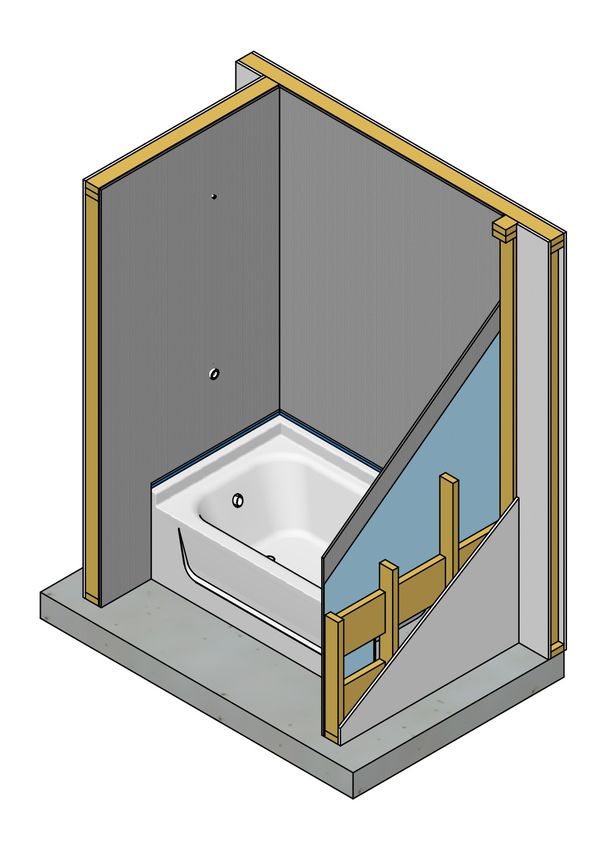
Measure Guideline: Water Management at
     Tub and Shower Assemblies

                   Prepared for:
                 Building America
           Building Technologies Program
  Office of Energy Efficiency and Renewable Energy
             U.S. Department of Energy

                    Prepared by:

                   Bruce Dickson
                   IBACOS, Inc.
                2214 Liberty Avenue
           Pittsburgh, Pennsylvania 15222

        Technical Monitor: Michael Gestwick
           Task Order KNDJ-0-40341-02
                  December 2011

                         i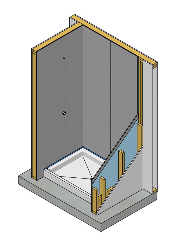
[This page left blank]

          ii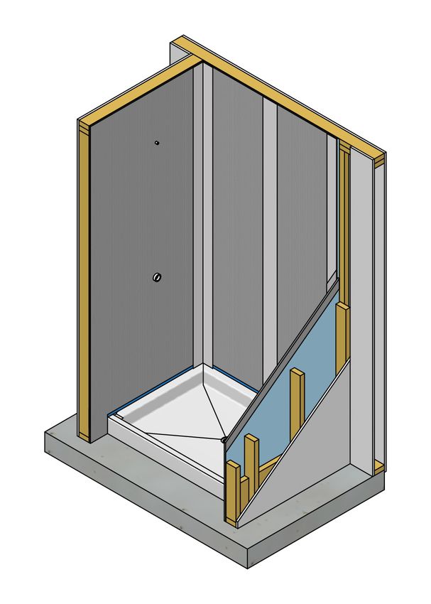
Contents
List of Figures ............................................................................................................................................ iv
Definitions ................................................................................................................................................... vi
Executive Summary .................................................................................................................................... 1
1 What Is Covered in This Measure Guide ............................................................................................ 2
      1.1 Audience for This Measure Guide .......................................................................................2
      1.2 Industry Relevance for This Measure Guide .......................................................................2
2     Common Practice and Inherent Risk Issues ..................................................................................... 3
3     Waterproofing Procedure .................................................................................................................... 5
      3.1 Bathtub-and-Shower Unit Procedure ...................................................................................5
      3.2 Tiled Shower Stall Procedure ............................................................................................10
4     Selection Criteria for Maximum Building Durability ....................................................................... 17
      4.1 Performance .......................................................................................................................17
      4.2 System Interactions ............................................................................................................17
      4.3 Cost Effectiveness..............................................................................................................17
      4.4 Codes and Standards ..........................................................................................................17
5 Homeowner Awareness and Education ........................................................................................... 18
References ................................................................................................................................................. 19

                                                                               iii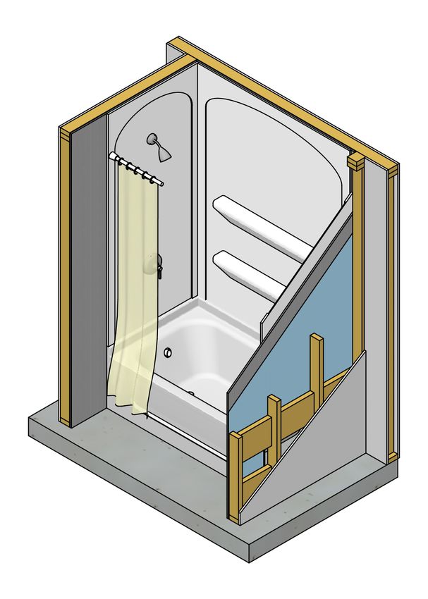
List of Figures
Figure 1. Typical shower and tub with surround and tiled shower stall. .............................................. 1
Figure 2. Backerboard material installed tight to the tub. ...................................................................... 3
Figure 3. Acrylic shower pan with the backerboard installed above the nailing flange. ..................... 4
Figure 4. Gap between the backerboard and shower pan nailing flange that will be a direct water
entry path into the wall assembly. ...................................................................................................... 4
Figure 5. Install blocking between the wall framing members where the shower or tub nailing
fin is located. The blocking must be wide enough to allow full adhesion of the straight
flashing to the nail fin and blocking. Make certain that the faces of the blocking pieces are
flush with the narrow faces of the studs, forming a smooth plane to which the flashing can
be attached. ........................................................................................................................................... 6
Figure 6. Install a minimum 6” square piece of self-stick flashing at the front bottom corners
of the pan............................................................................................................................................... 6
Figure 7. Install the bathtub, being careful not to damage the flashing at the front bottom
corners................................................................................................................................................... 7
Figure 8. Install a single piece of flashing that is folded into the corners over the nailing flange
and to the blocking at both corners. .................................................................................................. 7
Figure 9. Install a minimum 4” wide piece of self-stick flashing to the blocking and over the
nailing flange around all three sides of the tub................................................................................. 8
Figure 10. Install a weather-resistant barrier, such as housewrap or 15# building paper, over
the framing, making sure to overlap the flashing at the nailing flange to maintain the
shingling effect. .................................................................................................................................... 8
Figure 11. Fasten the approved wet-area backerboard, following the manufacturer’s
recommended fastening schedule, to the framing in the tub area that will be covered by
the surround. Do not set the backerboard directly on the tub unit. Install the backerboard
on the top edge of the nailing flange, or, at a minimum, make certain to maintain a
minimum ½” clear space between the tub deck and the bottom of the backerboard to
prevent moisture wicking. ................................................................................................................... 9
Figure 12. Install the wall surround panels, making certain to follow the manufacturer’s
requirements for proper adhesion, temporary bracing, and caulking. ........................................... 9
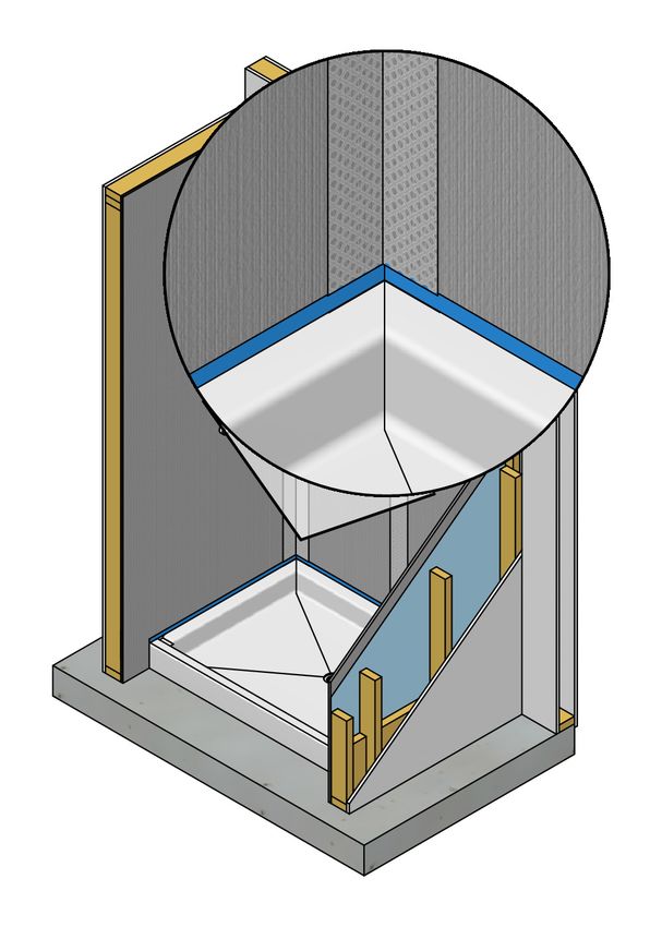
Figure 13. Section showing the proper layering of the waterproofing and finish details. ................ 10
Figure 14. Install blocking between the framing members surrounding the shower pan. The
blocking must be wide enough to allow full adhesion of the straight flashing to the nail fin
and blocking........................................................................................................................................ 11
Figure 15. Install a minimum 6” square piece of self-stick flashing at the front bottom corners
of the pan............................................................................................................................................. 12
Figure 16. Install the shower pan, being careful not to damage the flashing at the front bottom
corners................................................................................................................................................. 12
Figure 17. Install a single piece of flashing that is folded into the corners over the nailing flange
and to the blocking at both corners. ................................................................................................ 13
Figure 18. Install a minimum 4” wide piece of self-stick flashing to the blocking and over the
nailing flange around all three sides of the shower pan. ............................................................... 13
Figure 19. Install a weather-resistant barrier, such as housewrap or 15# building paper, over
the framing, making sure to overlap the flashing at the nailing flange to maintain the
shingling effect. .................................................................................................................................. 14
Figure 20. Install the approved wet-area backerboard on top of the nailing flange, following
the manufacturer’s recommended fastening schedule. Do not set the backerboard directly
onto the shower pan deck. Do not set the backerboard directly on the shower pan ledge.
Install the backerboard on the top edge of the nailing flange, or maintain a minimum ½”
clear space between the shower pan deck and the bottom of the backerboard to prevent
moisture wicking. ............................................................................................................................... 14
Figure 21. Seal all joints and corners in the backerboard with a minimum 2” wide fiberglass
mesh tape, embedded in thinset adhesive. ..................................................................................... 15
iv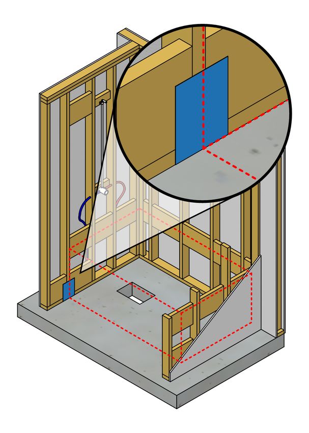
Figure 22. Install the tile, making sure to keep the weep holes in the pan clear to maintain
   an exit path for any moisture that penetrates the tile assembly and any water that drains
   down the backerboard. ...................................................................................................................... 15
Figure 23. Section showing the proper layering of the waterproofing and finish details. ................ 16

* Unless otherwise noted, all figures were created by IBACOS.

                                                                        v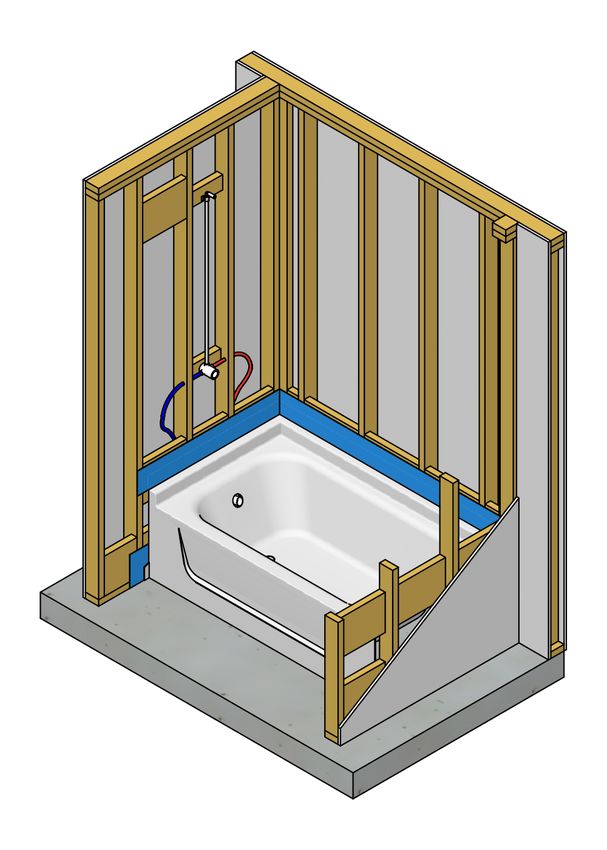
Definitions

Backerboard      A water-durable, mold-resistant panel for use under tile and other
                 finishes in a variety of interior and exterior applications.

Caulking         A material used to seal areas of potential air or water leakage into or out
                 of a building assembly.

Flashing         A thin continuous sheet of metal, plastic, rubber, or waterproof paper
                 used to prevent the passage of water through a joint in a wall, roof, or
                 other building assembly.

Gut Rehab        A major restoration project on a house or other building, ripping out
                 plaster walls back to the studs and rafters and replacing them along with
                 some or all of the trim, windows and doors, plumbing and electrical
                 systems, exterior siding, roof, etc.

Nailing Flange   A plastic apron-like piece that extends above a tub deck or shower pan
                 that enables the fixture to be fastened to framing.

Shower Pan/      A preformed single piece of molded acrylic plastic that is used in place
Receptor         of a shower base liner. The pan is designed with sidewalls and a sloped
                 floor that contains and directs water to a drain that is molded into the
                 pan.

Waterproof       A coating capable of stopping penetration of water or moisture.

Wick             To absorb or draw off (liquid) by capillary action.

                                          vi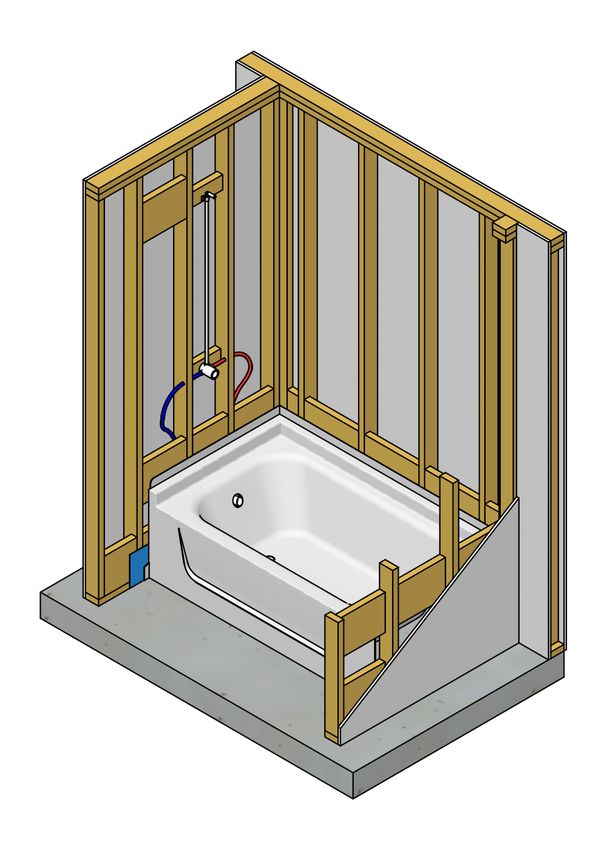
Executive Summary
When conducting a total gut rehab of a structure or constructing a new home, best practice
installation and detailing for effective waterproofing are critically important at bathtub and
shower assemblies. Water management issues in a structure may go unrecognized for long
periods, so that when they are finally observed, the damage from long-term water exposure is
extensive. A gut rehab is often undertaken when a home has experienced a natural disaster or
when the homeowners are interested in converting an old, high-energy-use building into a high-
quality, efficient structure that meets or exceeds one of the national energy standards, such as
ENERGY STAR or LEED for homes.

During a gut rehab, bath areas need to be replaced with diligent attention to detail. Employing
effective water management practices in the installation and detailing of tub and shower
assemblies will minimize or eliminate water issues within the building cavities and on the
finished surfaces. A residential tub-and-shower surround or shower-stall assembly is designed to
handle a high volume of water—2.5 gallons per minute, with multiple baths occurring during a
typical day (see Figure 1). Transitions between dissimilar materials and connections between
multiple planes must be installed with care to avoid creating a pathway for water to enter the
building assemblies. Due to the high volume of water and the consequential risk of water damage
to the home’s structure, a comprehensive water management system is imperative to protect the
building assemblies underlying the finish surround of tub and shower areas. At each stage of
construction, successive trades must take care not to create a defect nor to compound or cover up
a previous trade’s defect. Covering a defect hides the inevitable point of failure and may even
exacerbate the situation.

              Figure 1. Typical shower and tub with surround and tiled shower stall

                                                1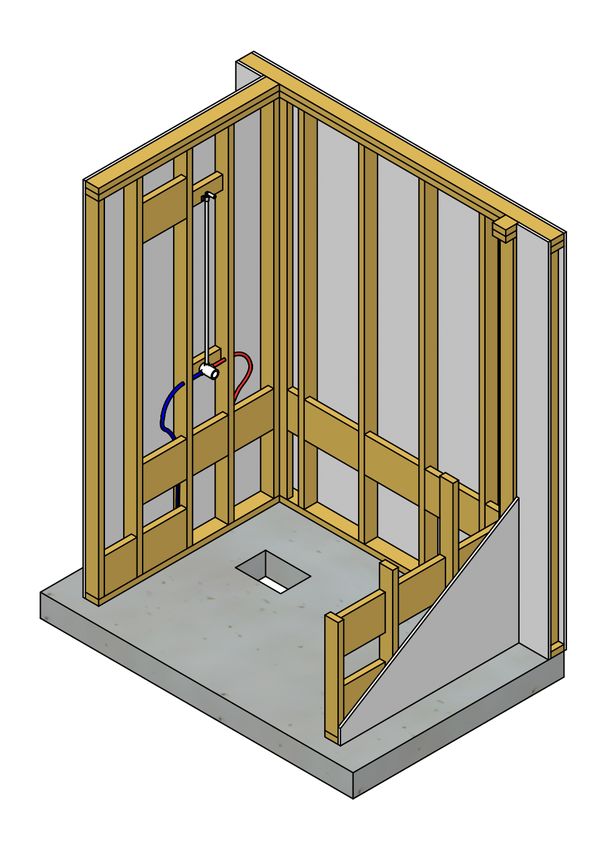
1 What Is Covered in This Measure Guide
This measure guide covers the fundamental waterproofing strategies for tub and shower
assemblies. These best practices of detailing and installation will minimize or eliminate water
issues in bath areas. Although many bath assemblies are available, this guide demonstrates
methods applicable to two of the most common styles installed in today’s homes. The two
installations covered in this guide are a combined tub and shower unit with a three-piece acrylic
surround and a standalone shower stall with a preformed acrylic base and tile surround.

1.1 Audience for This Measure Guide
This measure guide will benefit homeowners, tile installers, plumbing contractors, retrofit
contractors, architects, and material suppliers.

1.2 Industry Relevance for This Measure Guide
Whether the remodeling efforts in the bath or shower area are the result of a natural disaster, a
gut rehab retrofit, or a simple upgrade and improvement of the existing bath, implementing
effective waterproofing strategies beneath the finish surround will ensure a trouble-free and
durable bath assembly for homeowners.

                                                 2
2 Common Practice and Inherent Risk Issues
In the residential construction industry, the myth persists that the finish surround on a bathtub or
shower wall is 100% waterproof and that no additional detailing is necessary to prevent water
from entering the underlying wall and floor assemblies. Although backerboards are waterproof
or water resistant, the many material transitions between the backerboard, the finish surround,
and the door assembly are prone to water entry and subsequent damage to the finished surfaces
and framing.
A common—but ill-advised—practice when retrofitting an existing tub or shower surround is to
install the backerboard directly over the nailing flange, with the bottom edge of the backerboard
sitting directly on the tub or the shower pan (see Figure 2). The direct contact between the
shower pan and backerboard could lead to the backerboard wicking up any water that gets past
the finish surround. Over time, continuous wicking will cause the tile or acrylic surround to
loosen at the base and wick moisture toward the underlying framing. It is important not to
assume that the caulking at the base of the surround panels is 100% tight at all times. Even if the
caulking has deteriorated, the waterproofing strategy described in Section 3 should be effective
enough to prevent water entry.
Figure 2. Backerboard material installed tight to the tub
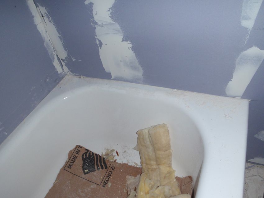
Another very common practice is to install the backerboard above the nailing flange without any
protection between the two materials (see Figure 3). If the shower pan is located on an exterior
wall, the gap between the pan and the backerboard will form a direct path for any water
penetrating the grout joints to get to the framing components and insulation (see Figure 4).
3Figure 3. Acrylic shower pan with the backerboard installed above the nailing flange
Figure 4. Gap between the backerboard and shower pan nailing flange that will be a direct water
entry path into the wall assembly
To minimize the potential of water-related issues in shower and tub assemblies, it is best to
implement a comprehensive flashing and waterproofing strategy before installing the finish
surround. The waterproofing strategy described in Section 3 will protect the underlying framing
and building components from water damage.
43 Waterproofing Procedure
In both of these common retrofits, all of the plaster or wallboard has been removed to expose the
framing as part of a gut rehab. In the first retrofit (Section 3.1), the homeowner is having a
combination bathtub-and-shower unit installed. In the second strategy (Section 3.2), the
homeowner is having a preformed acrylic shower receptor installed, with ceramic tile as the
finish surround.
3.1 Bathtub-and-Shower Unit Procedure
One of the most critical areas to detail is the transition from the nailing flange of the bathtub to
the framing. The first step toward a successful retrofit is to install blocking between the framing
members surrounding the tub (see Figure 5). Blocking must be wide enough to allow full
adhesion of the butyl-based self-stick flashing to the nailing flange and blocking (minimum 2 in.
× 6-in. blocking is recommended). Make certain that the faces of the blocking pieces are flush
with the narrow faces of the studs, forming a smooth plane to which the flashing can be attached.
The following best practice procedure will ensure an effective waterproofing strategy:
1. Install a minimum 6-in.2 piece of self-stick flashing at the front bottom corners of the pan
or tub (see Figure 6). This initial piece of flashing protects the vulnerable bottom corners
of the framing from water intrusion.
2. Install the bathtub, being careful not to damage the previously installed flashing at the
bottom front corners (see Figure 7).
3. Install a single piece of flashing that is folded into the corners over the nailing flange and
to the blocking at both corners (see Figure 8).
4. Install a minimum 4-in. wide piece of self-stick flashing to the blocking and over the
nailing flange around all three sides of the tub (see Figure 9).
5. Install a weather-resistant barrier, such as house wrap or 15-lb. building paper, over the
framing, making sure to overlap the previously installed flashing at the nailing flange to
maintain the shingling effect (see Figure 10).
6. Fasten the approved wet-area backerboard, following the manufacturer’s recommended
fastening schedule, to the framing in the tub area that will be covered by the surround. Do
not set the backerboard directly onto the tub unit. Install the backerboard on the top edge
of the nailing flange or, at a minimum, make certain to maintain a minimum ½ in. clear
space between the tub deck and the bottom of the backerboard to prevent moisture
wicking (see Figure 11).
7. Install the surround panels, making certain to follow the manufacturer’s requirements for
proper adhesion, temporary bracing, and caulking (see Figure 12).
Figure 13 shows the proper layering of the waterproofing and finish details.
5Figure 5. Install blocking between the wall framing members where the shower or tub nailing fin is
located.
The blocking must be wide enough to allow full adhesion of the straight flashing to the nail fin and
blocking. Make certain that the faces of the blocking pieces are flush with the narrow faces of the
studs, forming a smooth plane to which the flashing can be attached.
Figure 6. Install a minimum 6-in.2 piece of self-stick flashing at the front bottom corners of the
pan.
6Figure 7. Install the bathtub, being careful not to damage the flashing at the front bottom corners.
Figure 8. Install a single piece of flashing that is folded into the corners over the nailing flange and
to the blocking at both corners.
7Figure 9. Install a minimum 4-in. wide piece of self-stick flashing to the blocking and over the
nailing flange around all three sides of the tub.
Figure 10. Install a weather-resistant barrier, such as house wrap or 15-lb. building paper, over the
framing, making sure to overlap the flashing at the nailing flange to maintain the shingling effect.
8Figure 11. Fasten the approved wet-area backerboard, following the manufacturer’s recommended
fastening schedule, to the framing in the tub area that will be covered by the surround.
Do not set the backerboard directly on the tub unit. Install the backerboard on the top edge of the
nailing flange, or, at a minimum, make certain to maintain a minimum ½-in. clear space between
the tub deck and the bottom of the backerboard to prevent moisture wicking.
Figure 12. Install the wall surround panels, making certain to follow the manufacturer’s
requirements for proper adhesion, temporary bracing, and caulking.
9Figure 13. Section showing the proper layering of the waterproofing and finish details.
3.2 Tiled Shower Stall Procedure
Before applying the tile substrate, it is critical to implement a comprehensive flashing strategy so
that any water that penetrates through the grout joints or through transitions between materials
cannot reach the vulnerable framing and lead to long-term water damage. The first step toward a
successful retrofit is to install blocking between the framing members surrounding the shower
pan (see Figure 14). Make sure the blocking is wide enough to allow for complete adhesion of
the 4-in. wide butyl-based, self-stick flashing to the wood blocking and over the nailing flange of
the pan (minimum 2-in. × 10-in. blocking is recommended). Make certain that the faces of the
blocking pieces are flush with the narrow faces of the studs, forming a smooth plane to which the
flashing can be attached. The following best practice procedure will ensure an effective
waterproofing strategy:
1. Install a minimum 6-in.2 piece of self-stick flashing at the front bottom corners of the pan
(see Figure 15). This initial piece of flashing protects the vulnerable bottom corners of
the framing from water intrusion.
2. Install the shower pan, being careful not to damage the flashing at the bottom front
corners (see Figure 16).
3. Install a single piece of flashing that is folded into the corners over the nailing flange and
to the blocking at both corners (see Figure 17).
4. Install a minimum 4-in. wide piece of self-stick flashing to the blocking and over the
nailing flange around all three sides of the shower pan (see Figure 18).
105. Install a weather-resistant barrier, such as house wrap or 15-lb. building paper, over the
framing, making sure to overlap the flashing at the nailing flange to maintain the
shingling effect (see Figure 19).
6. Install the approved wet-area backerboard on top of the nailing flange. Do not set the
backerboard directly onto the shower pan deck. Install the backerboard on the top edge of
the nailing flange or, at a minimum, make certain to maintain a minimum ½ in. clear
space between the shower pan deck and the bottom of the backerboard to prevent
moisture wicking from the shower pan deck into the backerboard. Make certain to follow
the manufacturer’s recommended fastening schedule for the approved backerboard (see
Figure 20).
7. Seal all joints and corners in the backerboard with a minimum 2-in. wide fiberglass mesh
tape, embedded in thinset adhesive (see Figure 21).
8. When installing the tile finish, make certain to keep the weep holes on the shower pan
clear of grout in order to maintain an exit path for any moisture that penetrates the tile
assembly or any water that drains down the backerboard (see Figure 22).
See Figure 23 for a section detail of the waterproofing and finish layers.
Figure 14. Install blocking between the framing members surrounding the shower pan.
The blocking must be wide enough to allow full adhesion of the straight flashing to the nail fin and
blocking.
11Figure 15. Install a minimum 6-in.2 piece of self-stick flashing at the front bottom corners of the
pan.
Figure 16. Install the shower pan, being careful not to damage the flashing at the front bottom
corners.
12Figure 17. Install a single piece of flashing that is folded into the corners over the nailing flange
and to the blocking at both corners.
Figure 18. Install a minimum 4-in. wide piece of self-stick flashing to the blocking and over the
nailing flange around all three sides of the shower pan.
13Figure 19. Install a weather-resistant barrier, such as house wrap or 15-lb. building paper, over the
framing, making sure to overlap the flashing at the nailing flange to maintain the shingling effect.
Figure 20. Install the approved wet-area backerboard on top of the nailing flange, following the
manufacturer’s recommended fastening schedule.
Do not set the backerboard directly onto the shower pan deck. Do not set the backerboard directly
on the shower pan ledge. Install the backerboard on the top edge of the nailing flange, or maintain
a minimum ½-in. clear space between the shower pan deck and the bottom of the backerboard to
prevent moisture wicking.
14Figure 21. Seal all joints and corners in the backerboard with a minimum 2-in. wide fiberglass
mesh tape, embedded in thinset adhesive.
Figure 22. Install the tile, making sure to keep the weep holes in the pan clear to maintain an exit
path for any moisture that penetrates the tile assembly and any water that drains down the
backerboard.
15Figure 23. Section showing the proper layering of the waterproofing and finish details.
164 Selection Criteria for Maximum Building Durability
4.1 Performance
The use of high-quality butyl-based self-stick flashing products to protect all building assemblies
from water will minimize the potential for long-term moisture damage and any occurrence of
mold issues in the wet areas of bathrooms.
Installing a drainage plane material beneath all backerboards in shingle fashion will protect
framing from moisture damage and potential mold issues.
4.2 System Interactions
The waterproofing methods described in this guide lend themselves to long-term building
durability and do not have any direct interactions with other house systems.
4.3 Cost Effectiveness
The costs associated with implementing the waterproofing methods outlined in this guide should
be minimal due to the small quantity of material needed and the relatively minimal amount of
labor to install.
4.4 Codes and Standards
There are no applicable building codes or standards that apply to the waterproofing details
outlined in this guide. Building codes prohibit using water-resistant sheetrock (green board) in a
shower enclosure. Instead, use fiber cement, fiber-mat reinforced cement, glass mat gypsum
backers, and fiber-reinforced gypsum backers.
175 Homeowner Awareness and Education
It is best to educate the homeowners about the effects of water on unprotected building materials
in the bathroom and the importance of drying any areas outside of the shower and tub to
minimize these effects. The importance of the weep holes and ensuring that those holes remain
unsealed to provide drainage should be discussed with the homeowners.
18References
International Residential Code® (2009). 2009 International Residential Code® for One- and Two-
Family Dwellings. Country Club Hills, IL: International Code Council; Chapter 7.
TCA 2006. 2006 Handbook for Ceramic Tile Installation. Anderson, SC: Tile Council of North
America.
19DOE/GO-102011-3466 ▪ December 2011 Printed with a renewable-source ink on paper containing at least 50% wastepaper, including 10% post-consumer waste.
You can also read