SANDIA REPORT Megagauss Field Generation for High-Energy-Density Plasma Science Experiments
←
→
Page content transcription
If your browser does not render page correctly, please read the page content below
SANDIA REPORT
SAND2008-7015
Unlimited Release
Printed October 2008

Megagauss Field Generation for High-
Energy-Density Plasma Science
Experiments
Kenneth W. Struve, John L. Porter, and Dean C. Rovang

Prepared by
Sandia National Laboratories
Albuquerque, New Mexico 87185 and Livermore, California 94550

Sandia is a multiprogram laboratory operated by Sandia Corporation,
a Lockheed Martin Company, for the United States Department of Energy’s
National Nuclear Security Administration under Contract DE-AC04-94AL85000.

Approved for public release; further dissemination unlimited.
Issued by Sandia National Laboratories, operated for the United States Department of Energy by
Sandia Corporation.

NOTICE: This report was prepared as an account of work sponsored by an agency of the United
States Government. Neither the United States Government, nor any agency thereof, nor any of
their employees, nor any of their contractors, subcontractors, or their employees, make any
warranty, express or implied, or assume any legal liability or responsibility for the accuracy,
completeness, or usefulness of any information, apparatus, product, or process disclosed, or
represent that its use would not infringe privately owned rights. Reference herein to any specific
commercial product, process, or service by trade name, trademark, manufacturer, or otherwise,
does not necessarily constitute or imply its endorsement, recommendation, or favoring by the
United States Government, any agency thereof, or any of their contractors or subcontractors. The
views and opinions expressed herein do not necessarily state or reflect those of the United States
Government, any agency thereof, or any of their contractors.

Printed in the United States of America. This report has been reproduced directly from the best
available copy.

Available to DOE and DOE contractors from
         U.S. Department of Energy
         Office of Scientific and Technical Information
         P.O. Box 62
         Oak Ridge, TN 37831

         Telephone:         (865) 576-8401
         Facsimile:         (865) 576-5728
         E-Mail:            reports@adonis.osti.gov
         Online ordering:   http://www.osti.gov/bridge

Available to the public from
         U.S. Department of Commerce
         National Technical Information Service
         5285 Port Royal Rd.
         Springfield, VA 22161

         Telephone:         (800) 553-6847
         Facsimile:         (703) 605-6900
         E-Mail:            orders@ntis.fedworld.gov
         Online order:      http://www.ntis.gov/help/ordermethods.asp?loc=7-4-0#online

                                                2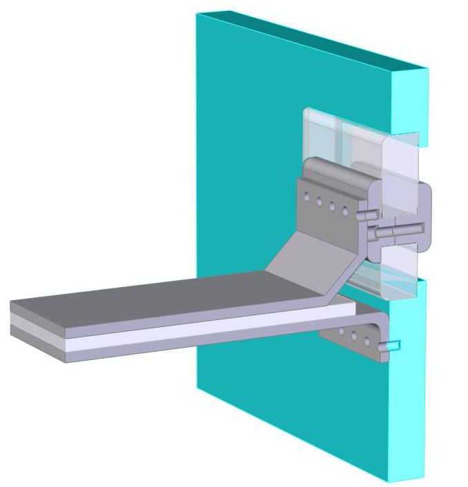
SAND2008-7015
                                    Unlimited Release
                                   Printed October 2008

  Megagauss Field Generation for High-
    Energy-Density Plasma Science
            Experiments
                 Kenneth W. Struve, John L. Porter, and Dean C. Rovang
                         High-Energy Density Physics Division
                             Sandia National Laboratories
                                     P.O. Box 5800
                            Albuquerque, NM 87185-1194

                                         Abstract

There is a need to generate magnetic fields both above and below 1 megagauss (100 T)
with compact generators for laser-plasma experiments in the Beamlet and Petawatt test
chambers for focused research on fundamental properties of high energy density
magnetic plasmas. Some of the important topics that could be addressed with such a
capability are magnetic field diffusion, particle confinement, plasma instabilities,
spectroscopic diagnostic development, material properties, flux compression, and
alternate confinement schemes, all of which could directly support experiments on Z.
This report summaries a two-month study to develop preliminary designs of magnetic
field generators for three design regimes. These are, (1) a design for a relatively low-field
(10 to 50 T), compact generator for modest volumes (1 to 10 cm3), (2) a high-field (50 to
200 T) design for smaller volumes (10 to 100 mm3), and (3) an extreme field (greater
than 600 T) design that uses flux compression. These designs rely on existing Sandia
pulsed-power expertise and equipment, and address issues of magnetic field scaling with
capacitor bank design and field inductance, vacuum interface, and trade-offs between
inductance and coil designs.

                                             3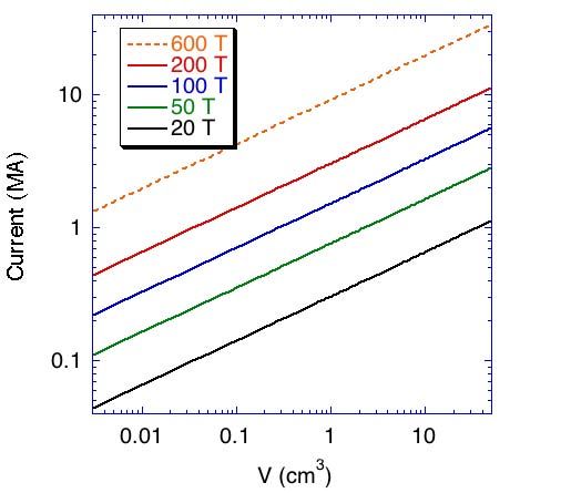
Acknowledgments
Dwight Rickel, Charles Mielke, Stefan Hansel, LANL

                        4
Contents
Introduction ……………………………………………………………………..…… 7
Magnetic Field Generation ............................................................................ 8
      Mechanical strength …………………………………………………...……… 8
      Coil design options ………………………………………...………………… 10
      Single-turn coils ………………………………………...……………………. 11
      Coil Inductance …………………………………………………...………….. 15
Driver Requirements ………………………………………………….…………. 16
      Conceptual Design …………………………………………………...……… 16
      Transmission line considerations ………..………………………………… 18
      Scaling …………………………………………………………………….….. 19
      Switching ………………………………………………………………….….. 20
      Vacuum feed-through ……………………….………………………………. 20
Specific Applications ……………………………………………………….……. 21
      Small volume, low field ……………………………………………………… 21
      Small volume, high field …………………………………………………….. 23
      Flux compression, extremely high field ……………………….…………… 26
Conclusions ………………………………………………………….…………….. 27

References …………………………………………………………………………. 29

Figures
        1    Magnetic pressure as a function of magnetic field strength ……….….…… 8
        2    Two-megagauss single-turn coil design …………………………..…..…... 12
        3    Same coil assembly after a shot ……………………………………...……. 13
        4    Current needed to drive a Helmholtz coil vs. coil radius ………………….. 14
        5    Current needed to drive a Helmholtz coil vs. field volume ..……………… 14
        6    Scaling of the magnetic coil inductance vs. radius for a single-turn coils … 15
        7    The current source for the magnetic coil is modeled as an LRC circuit …... 16
        8    Normalized capacitor voltage and current ……………………...…………. 18
        9    Capacitance needed to drive 2 MA vs. capacitor charge voltage …………. 19
        10   Conceptual design of a bi-plate vacuum window …………….....………… 21
        11   A 15 T magnetic field coil driver ………………………………….……… 23
        12   Mechanical layout of the 100+ T current driver by Portugall …..………… 25
        13   Mechanical layout of a 200 T driver using a bi-plate transmission line …... 25
        14   200 T driver using switches on each capacitor …………………….....…… 26

Tables
        1    Yield and ultimate (tensile) strength of several materials …..……………… 9
        2    Coil currents for the three optional designs …….…………………………. 15
        3    Current needed to produce 15 T with a Helmholtz coil pair ……………… 22
        4    Driver parameters for a 15 T single-turn magnetic field coil …...………… 22

                                                   5
5   Current and field vs. charge voltage for the 15 T coil driver ……………… 23
6   Driver parameters for a 200 T coil ………………………………………… 24
7   Current and field vs. charge voltage for the 200 T coil driver …………….. 24

                                  6
Introduction
This report is the summary of a late-start laboratory directed research and development
(LDRD) conceptual design project to investigate high magnetic field generation for a
variety of applications in the Pulsed Sciences Center at the Sandia National Laboratories,
LDRD 08-1427. It represents only two months of work, and therefore cannot be a
complete survey. But we do propose several conceptual designs, which of course, will
need to be further developed. Efforts were made to match the here-proposed designs
with capability existing within the center. This work is also a prelude to a follow-on
LDRD project for magnetic field generation for cluster plasma confinement. The
approach for this work has been to start with the required field strengths and volumes for
the various applications, and to match designs to these requirements.

Many high-energy density physics experiments and materials properties measurements
need high magnetic fields at levels up to 1 megagauss (100 T) or greater. These include
laser-plasma experiments on the Beamlet and Petawatt lasers, and magnetically stabilized
and flux compression experiments on the Z accelerator. Many of these investigate
fundamental properties of high energy density plasmas embedded in strong magnetic
fields. Some of the important topics that can be addressed with such a capability are
magnetic field diffusion, particle confinement, plasma instabilities, spectroscopic
diagnostic development, material properties, and flux compression confinement schemes.

Because of the size of the laser and z-pinch facilities, it is not practical to bring the
experiment to the magnetic field source. Rather, experiments on these machines require
bringing a portable magnetic field generating device to the machine. Furthermore, many
of these experiments are in vacuum and need a high-current, high-voltage vacuum feed-
through, a non-trivial task. Some of the experiments also require relatively large (~ 30
cm3) volumes, whereas some can be done with much smaller (~ 1 cm3) volumes.

For magnetic field strengths exceeding about 30 T mechanical strength of materials used
in the construction of the magnet is generally exceeded. Therefore, except for magnets
built with expensive reinforcing techniques and cryogenically cooled, single-use, throw-
away magnets are generally used, driven by a pulsed current source.

In the following we discuss the scaling of mechanical pressure with magnetic field
strength, magnetic field coil options, and scaling of magnetic field with driving current
and volume. We then present conceptual designs for three applications. These are (1) a
low field (~ 15 T), small volume (~ 1 cm3) design for potential laser flux compression
experiments, (2) a high field (100 to 200 T), small volume (~ 1 cm3) for laser-plasma
experiments, and (3) a two-stage, flux compression design that can produce up to 600 T.
Techniques for generating a low field (~ 30 T), large volume (~ 30 cm3) device for
experiments on magnetically-immersed diodes and for potential experiments on Z have
been previously reported. [1]

                                            7
Magnetic Field Generation
Of primary concern for the design of a magnetic field generator is the mechanical
strength of the magnet, and its ability to withstand the mechanical force exerted by the
intense magnetic field. For continuously operating or long-pulse time magnets, resistive
heating of the coils is also critical. The typical limit for high field, continuously
operating magnets is about 30 T. Long-pulse magnets are usually made using high
tensile-strength steels and dielectric materials such as Zylon [2] to support copper or
copper-alloy coil windings.

At this time, the maximum field achieved in a slow-pulse magnet is 90 T. This magnet is
located at the National High-Magnetic Field Laboratory at the Los Alamos National
Laboratory.[3] It is approximately 2 m in diameter, and 2 m tall, and is driven by an 800
MW DC power supply. The AC power for the supply comes from energy that is stored in
an electromechanical generator the size of a locomotive. The magnet has multiple shells
of copper windings that resistively heat during a shot. The copper windings also undergo
an elastic-plastic deformation and press against supporting Zylon and steel shells. They
are cooled with liquid helium through slots between the shells. The volume of the peak
field is of order 100 cm3.

Because of the size and complexity of these large magnets, high field (generally > 30 T)
magnets are either short-pulse multi-turn-coil solenoids (30 to 60 T), or single-turn
unsupported coils that are destroyed each shot and which can achieve up to 200 T. Even
higher fields can be achieved with multiple nested shells where flux within an inner shell
is compressed by the fast implosion of an outer shell.

Mechanical strength

With a solenoidal magnet or single-turn coil, the pressure P exerted by the magnetic field
of the coil on its metallic surface for fast-rising pulses is

                                                   B2
                                           P =         ,                                   (1)
                                                  2 μo

where B is the magnetic field strength and µo the permeability of free space. A fast-rising
pulse is one where the magnetic field does not diffuse through the coil. This radial
pressure transfers to an azimuthal tension or hoop stress in the solenoid. This tension can
be adjusted by increasing the thickness of the coil, much as the strength of a water pipe is
increased by increasing its thickness. However, for thick pipes or coils the tension has a
radial dependence, with the highest tension on the inside of the pipe. Assuming that
current flows only in a thin layer on the inner surface of the coil the azimuthal stress σϕ as
a function of radius r is related to the radial pressure P from eq. 1 by the Lame′ equation

                                              8
P a12 ⎛ a22 ⎞ a1
σ ϕ (r ) = ⎜1 + ⎟ ≈ P for t = a2 − a1megagauss (100 T) the magnetic pressure exceeds the strength of any material.
Therefore, for high-field designs only single-use, exploding coil designs can be
considered. For option 1, which only requires 15 T, non-destructive coil designs may be
possible if dimensions are carefully chosen.
Fig. 1. Magnetic pressure as a function of magnetic field strength.
Coil design options
For megagauss and greater pulsed fields single-use coil designs are required. If specially
designed to handle stresses, coils with fields between approximately 30 to 50 T can be
made for multiple use. However, above that replaceable coils are required.
Single-turn coil designs are generally best for high field applications for several reasons:
First, multiple-turn coils introduce higher inductance that can limit the current, rise-time,
and resulting peak magnetic field that can be achieved. Second, multiple-turn coils are
more expensive and time-consuming to build, and thus may not be practical for single
use. Third, because of the peak currents required, large conductor cross-sections are
needed to carry the current, making coil fabrication more difficult.
Another alternative is a Bitter coil.[7] This design consists of multiple parallel disks with
each slit at one azimuth. Each disk is connected to its neighbor so that the disks are
connected in series. This concept allows high current densities when the disk radius and
10width are adjusted to accommodate the high current. But a Bitter coil also has higher
inductance than a single-turn coil with the inductance proportional to the number of
disks. It also experiences the same azimuthal stress as other solenoidal designs, and is
destroyed with each shot with megagauss-level fields. Since a Bitter-coil assembly is
more tedious to build than single-turn coils, and because of its higher inductance, it is
probably not useful for single-shot use.
Single-turn coils
The most simple coil design is a single-turn loop. The magnetic field B on the axis of the
coil with radius a with current I is
μo I a2 I
Bz ( z) = where Bz (0) = 0.5 μ o , (4)
( )
32
2 z2 + a 2 a
and z is measured along the axis from the center of the coil. The inductance for a single-
turn coil L ≅ d/dI [πa2Bz(0)] = πμoa/2.
For two parallel loops separated a distance 2l with each carrying the same current I, the
magnetic field on axis is [7]
[
a2 ⎧ 2
] [ ] ⎫.
−3 2 −3 2
Bz ( z) = μ o I ⎨ a + (l − z)
2
+ a 2 + (l + z)2 ⎬ (5)
2 ⎩ ⎭
This field represents a magnetic mirror configuration if 2l > a, where there is a minimum
in the field strength at z = 0. If 2l = a, which defines a Helmholtz coil pair, the field is
uniform in z for z < a to the fourth power of z/a. If one current source drives the pair of
coils, then the current I through each coil of eq. 5 is half of the drive current Id. Thus the
magnetic field on the axis between the Helmholtz coils is
4 μo I d
Bz ( z < a) ≅
532
a
[ ] I
1 + ... + O( z / a) 4 ≅ 0.358 μ o d .
a
(6)
Similarly, the inductance of the Helmholtz coil is L ≅ 0.358πμoa.
Eqs. 4 – 6, however, are only approximations since they assume that the current is in an
infinitesimally small filament. Because of the high currents needed to produce high
fields and the resulting high current densities, these conductors must have finite
thickness. For a thick axisymmetric, single-turn solenoid, assuming uniform current
density, with width 2b and inner and outer radii a1 and a2 respectively, the on-axis field is
[8]
11μ o I ⎧⎪ b − z ⎛ a + a 2 + (b − z)2 ⎞ b + z ⎛ a + a 2 + (b + z)2 ⎞ ⎫⎪
Bz ( z) = ⎨ ln ⎜ 2 2
⎟+ ln ⎜ 2 2
⎟⎬ . (7)
4b ⎪ a2 − a1 ⎝ a + a 2 + (b − z)2 ⎠ a2 − a1 ⎝ a + a 2 + (b + z)2 ⎠ ⎪
⎩ 1 1 1 1 ⎭
The inductance for this coil can be estimated by multiplying Bz(0) from eq. 7 by πa12/I.
But even this equation is not correct for fast-rising current drives. If the current rise is
sufficiently fast the current only resides within a skin-depth of the surface of the
conductor. Thus the current is carried primarily on the inner surface of the coil, and on
the two radial faces. This gives a mirror-like profile of the field within the coil. By
careful choice of the width, radius, and thickness of a single conductor it is possible to
tailor the field profile to be either mirror-like, or uniform in z. This design is done
numerically based on the parameters of the current source.
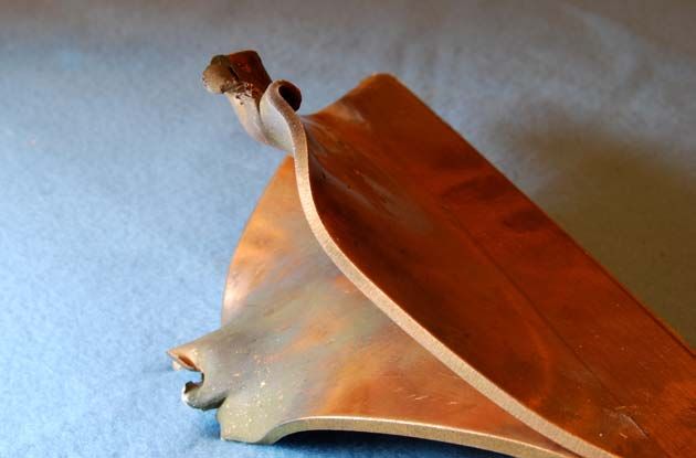
Therefore, the simplest magnet design that produces a high field is a single-turn coil,
driven by a strip-line transmission line, as done by Portugall,[9] and duplicated by
Mielke.[10] This design consists of a single copper sheet that is cut as two converging
triangles connected by a thin strip. The two triangular sections are folded together over a
mandrel that maintains a diameter in the strip region, and thereby become a coil. Mielke
does another step in that he compresses the formed coil with the mandrel still inserted
into a die to form a coil with the exact dimensions desired. The completed copper coil is
shown in fig. 2. The coil has a 10 mm inner diameter and is 10 mm wide. The conductor
thickness is 3 mm. Not shown in the figure is the mylar insulation that is placed between
the two conductors of the transmission line during the shot, and which extends into the
coil region, forming a loop. This design has been used for fields up to 2 megagauss
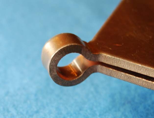
(200T). A picture of an identical coil, but after being fired, is shown in fig. 3.
Fig. 2. Two-megagauss single-turn coil design, courtesy C. Mielke, LANL.
12Fig. 3. Same coil assembly after a shot, courtesy C. Mielke.
We can estimate the current needed to produce fields for a variety of field volumes and
strengths, using eq. 6, which scales with current and coil radius. With this equation we
presume a uniform field configuration in a Helmholtz configuration. Actual field
strength may differ slightly depending on current rise-time, material thickness, and coil
width. But this analysis provides the scaling necessary to determine current needed for
volumes and fields of interest. A plot of current vs. coil radius for several magnetic fields
is shown in fig. 4. In fig. 5 is a plot of current vs. coil volume, which is the volume
between the coils in a Helmholtz configuration, πa3.
Thus, the currents needed to drive single-turn coils to achieve the fields and volumes of
the three options mentioned earlier are 200 kA (option 1), 1.5 to 3.0 MA (option 2), and
an unrealistically high field of 30 MA for the highest field and largest volume (option 3.)
These values are summarized in table 2. To drive the 1 cm diameter coil shown in fig. 2
to a 200 T peak field a peak current of 2.2 MA is required.
Similarly, the self-inductances of the coils can be estimated for each option, as given in
table 1, and based on volumes listed. The self-inductance for the Mielke coil, using eq. 7
for a1 = 5 mm, a2 = 8 mm, and 2b = 10 mm, is 16 nH. But, because of skin depth effects,
this number is only approximate.
13Fig. 4. Current needed to drive a Helmholtz coil vs. coil radius for several magnetic field
strengths.
Fig. 5. Current needed to drive a Helmholtz coil vs. field volume for several magnetic
field strengths. The 600 T design is likely not achievable with single-turn coil designs,
but must use a flux compression scheme with lower peak driving currents.
14Table 2. Coil currents required to achieve the peak fields and volumes for the three
optional designs considered.
Single-turn
Volume Current
Peak B (T) inductance
(cm3) (MA)
(nH)
Option 1 15 1 0.2 13
Option 2 100 - 200 1 1.5 - 3.0 13
Option 3 600 30 30 42
Coil Inductance
Inductance of the various coils scales with coil radius. These are plotted in fig. 6 versus
radius using the relations given above. The thick coil calculation is for a 10 mm wide
coil, 3 mm thick. It is clear from this plot that for large radii the coil can contribute
significant inductance to the circuit.
Fig. 6. Scaling of the magnetic coil inductance vs. radius for a single-turn coils.
15Driver Requirements
Conceptual Design
The driver that supplies the current for the magnetic field coils can be considered as a
simple LRC circuit, as shown in fig. 7. A bank of parallel capacitors is slow charged to
an initial voltage Vo, and then discharged through a switch that can tolerate both the
initial DC charge voltage, and the peak and integrated current of the discharging
capacitors. The discharge current is transferred to the magnetic coil through a low-
inductance transmission line. Topologically, the most reasonable transmission line is a b-
late. Parameters affecting the shape and magnitude of the current are the capacitance C
of the bank, the system inductance L and resistance R, and the capacitor charge voltage.
Fig. 7. The current source for the magnetic coil is modeled as an LRC circuit. If the
source is far from the coil then Lfeed is modeled as a transmission line rather than a
lumped circuit element.
The current produced by this circuit can be derived based on these parameters. Here the
inductance L is the sum of the inductances of the capacitor Lcap, the switch Lswitch, the
transmission line leading to the magnet Lfeed, and that of the magnetic field coil or coils
Lcoil. With the capacitor bank initially charged the switch closes at t = 0. Assuming
constant coil inductance, the current i(t) is
Vo −t / 2τ
i(t ) = e sin ω t
ωL
= Vo
C e −ω o t x
L 1− x 2
(
sin ω ot 1− x 2 )
(8)
1 1
where ω = − = ω o 1− x 2
LC (2τ )2
1 1 L
with ω o = , x = , and τ =
LC 2ω0τ R
The peak current Ip and time to peak Tp are
16C ⎛ x ⎛ 1− x 2 ⎞ ⎞
I p = Vo exp⎜ − tan −1 ⎜ ⎟⎟
L ⎝ 1− x
2
⎝ x ⎠⎠
(9)
x ⎛ 1− x 2 ⎞
Tp = 2 τ tan −1 ⎜ ⎟ .
1− x 2 ⎝ x ⎠
For small x (τ >> 1/ωo), these relations reduce to the more familiar,
C⎛ πx ⎞
I p = Vo ⎜1− + O( x 2 ) + ...⎟
L⎝ 2 ⎠
(10)
π
Tp =
2
(
LC 1 + O( x 2 ) + ... ) .
The voltage on the capacitor is
⎛ sin ω t ⎞
V (t ) = Voe −t / 2τ ⎜ + cosω t ⎟
⎝ 2ωτ ⎠
(11)
⎡ x
= Voe −ω o t x ⎢
⎣ 1− x
2
( ) ( ⎤
sin ω ot 1− x 2 + cos ω ot 1− x 2 ⎥ .
⎦
)
To avoid excessive voltage reversal of the capacitors, the series resistance R is generally
non zero. We find R by specifying a ring-over fraction f of the first negative voltage
swing as
−V (π / ω )
f ≡ = e −π /(2ωτ ) = e −πx / 1−x 2
. (12)
Vo
Solving for R we find the series resistance needed with this ring-over fraction as
L ln(1/ f ) L
R = 2 = 2 x. (13)
C ln (1/ f ) + π
2 2 C
A plot of the capacitor voltage and the circuit current, based on these equations, is shown
in fig. 8 for a ring-over voltage of 30%. Note that the peak current is reduced by 35%
over what it would be if there were no resistance in the circuit.
17( )
Fig. 8. Normalized capacitor voltage ( V (t ) / Vo ) and current ( i(t ) / Vo C / L ) for f = 0.3
vs. t/τ for ωτ = 1.30.
Transmission line considerations
The power from the current source is most efficiently delivered to the coil with a bi-plate
transmission line. Its TEM mode impedance is
μo g 377 g
Zbiplate = ≅ , (14)
εr εo w εr w
where g is the gap between the plates and w the width of the plates, and εr the dielectric
constant of the material between the plates. For very small gaps and large plate widths
this impedance can be very small, so that the product of impedance and the propagation
time, which is the inductance of the line, is small.
A coaxial transmission line could also have a similar small inductance. However, low
inductance transitions between the coaxial line and a bi-plate line would be difficult.
These would be needed at both the capacitors and at the magnetic field coil.
The magnetic field between the plates in a bi-plate line is μoI/w, so that the magnetic
pressure, according to eq. 1, is
18μo I 2
Pbiplate = . (15)
2 w2
Thus, for example, if the bi-plate is 1 m wide and carries a current of 1 MA, the pressure
pushing the plates apart is 0.63 MPa, or about 6 atmospheres (∼ 90 lbs/in2.) For this
reason mechanical clamping of the plates is necessary, and must be a serious design
consideration as the plates are made narrower or the current increased. However,
because of the short pulse length of the drive pulses these pressures represent short
impulses that may be easier to control than a sustained force.
Scaling
The size of the capacitor bank needed to produce the desired current for a particular
application is a function of the peak current, inductance, and charge voltage,
2
⎛ Ip⎞
C = L⎜ ⎟ . (16)
⎝ Vo ⎠
For example, the capacitance needed to produce 2 MA, neglecting system resistance and
for three inductances, is shown in fig. 9. We find that the capacitance needed to deliver 2
MA with a system inductance of 50 nH and a charge voltage of 100 kV is 20 μF.
Fig. 9. Capacitance needed to drive 2 MA for 20, 40, and 50 nH driver inductances vs.
capacitor charge voltage.
19Switching
The other crucial component of the driver circuit is the switch. It must be able to hold a
DC charge on the capacitors, able to carry the current of the discharge, and have low
enough inductance so that it does not appreciably add to the system inductance. With
current rise-times of about 1 μsec, which is typical for the higher current applications,
laser or other complicated triggering is not needed. Switching jitter of 5 to 10 ns is
tolerable.
Switches that could fill these requirements include electrically triggered rail-gap switches
that can handle currents exceeding 1 MA, [11] and gas-filled spark-gap switches,
especially if used in parallel. Potential candidates are the Sandia Marx bank switch [12],
the linear-transformer driver (LTD) switch, and the LMJ flash-lamp switch.[13]
Vacuum feed-through
A significant challenge for a coil-driver circuit is to operate the system in vacuum, which
can be required for some applications. Since it is not feasible to put the high-voltage
capacitors in vacuum, some mechanism must be used to transmit the high-current pulse
into a vacuum chamber. Vacuum windows for coaxial transmission lines are feasible,
but, as mentioned earlier, introduce other complications.
We see two potential solutions. One involves flux compression and using a small
diameter dielectric vacuum chamber that fits inside a large coil. The large outer coil,
which is in air, compresses a smaller-diameter, thin conducting shell inside the chamber.
If the region is pre-loaded with a low-level magnetic field, when the shell is compressed
very high field strengths can be achieved. The other solution is to use a vacuum window.
The vacuum window approach requires flaring the gap of a bi-plate line on both sides of
a dielectric vacuum window and to connect through the window with a rectangular block
that can be O-ring sealed to the window. This concept is shown in fig. 10. Potential
problems with this approach are that the flare volume increases inductance, and the need
to mechanically clamp the bi-plates to control mechanical shock and potential damage to
the window.
For example, if we consider a plate that is 50 cm (∼ 20”) wide, a flare height of 2.54 cm
(1”), and a flare length of 10 cm (4”) on either side of the window, the added inductance
is only 6.4 nH by eq. 14. However, the instantaneous pressure at the window, using eq.
15, is 100 MPa (1 kbar) for a 2 MA pulse. This pressure approaches the ultimate strength
of many materials, meaning that window damage can be expected. The only solution is
to make the window wider, which for some vacuum chambers may not be feasible.
20Fig. 10. Conceptual design of a bi-plate vacuum window.
Specific Applications
Based on the previous design considerations, we can now propose several design
concepts. The first is a small-volume, relatively low magnetic field design for use with
laser plasma experiments. The second is also a small volume design with high fields that
is suitable for cluster-fusion experiments, and the third uses a flux compression scheme
that can produce extremely high fields. A fourth possibility, which is not described here
but referred to earlier, would be a larger volume design suitable for flux compression
experiments.
Small volume, low field
A small volume low field driver can be made with a single 100 kV capacitor. The current
needed scales as the coil radius times the magnetic field strength, as given by eq. 6. For a
field strength of 15 T the current needed for several coil radii is shown in table 3. We
21choose 200 kA as a reasonable current goal, and estimate that inductance can be kept at
or below 200 nH. Using the expression for the peak current in eq. 8, we find that we
need 800 nF with a 100 kV charge with no series resistance. This capacitance can be
obtained with eight 100 nF, 50 kA series PDS capacitors from General Atomics [14], or
one 1.3 μF /100 kV series C capacitor, which is the capacitor used for PBFAII and Z.
We have many of the 1.3 μF capacitors available, and its use is less complicated. We
therefore choose the one-capacitor approach.
Table 3. Current needed to produce 15 T with a Helmholtz coil pair for several radii.
The 1.3 μF capacitor, which is 28 x 36 x 64 cm (11 x 14 x 25 inches) in size, has a low
inductance Syllac-style header, to which a high current gas switch can be mounted.
Options for the switch are a modified LTD switch, or a rotating-arc gas switch such as
the one used by the French for the LMJ laser flashlamps.[13] A conceptual design of
such a driver is shown in fig. 11.
Table 4. Driver parameters for a 15 T single-turn magnetic field coil.
22Fig. 11. A 15 T magnetic field coil driver using one 1.3 μF capacitor and high-current
gas switch. Power is transferred to a bi-plate strip-line (not shown) that drives the coil
through parallel high-voltage coaxial cables.
Table 5. Current and field vs. charge voltage for the 15 T coil driver.
Small volume, high field
For cluster fusion experiments it is desirable to have 100 to 200 T in a small volume.
Using the results of fig. 4 we choose a current of 2 MA for a coil radius of 5 mm. From
fig. 9 we find that the capacitance needs to be at least 20 μF for a system inductance of
50 nH, which is a reasonable estimate based on similar machines. Since we have 3.1
μF/100 kV capacitors available, we choose 8 capacitors for a total of 24.8 μF. We
choose 5 mΩ as the system resistance to provide circuit damping. These parameters are
summarized in table 6. Peak field to be expected for these parameters as a function of
bank charge voltage is given in table 7 for a 5 mm radius coil. In both tables the peak
23currents are reduced by ∼ 5% by the circuit resistance, using eq. 8. Note that if the
inductance is lower the field can be even larger.
Table 6. Driver parameters for a 200 T coil.
Table 7. Current and field vs. charge voltage for the 200 T coil driver.
There are two design concepts available for the driver. One is to use bi-plate
transmission lines from the capacitors to the coil and using rail-gap switches. This is the
concept of Portugall [9], as shown in fig. 12. The other is to use individual switches on
each capacitor and to connect the switch output to a remotely located bi-plate line with
sets of parallel coaxial cables. Since both concepts are valid approaches, we discuss each
individually.
The bi-plate transmission line approach was developed by Portugall, and is shown in fig.
12. Here the upper and lower plates are folded open so that each can be individually
seen. Four 6 μF/60 kV capacitors are switched with two rail-gap switches. Total
inductance for this system is less than 30 nH. Our concept is similar, as shown in fig. 13,
but the capacitors are located in a tank so that the capacitors and switches can be in under
oil. The tank, which measures 1.22 x 2.13 x 0.97 m (4’ x 7’ x 38”), contains the oil
insulation and functions as a safety enclosure around the capacitors. The transmission
line must bend up to come over the tank wall and narrows to the magnetic field coil. Not
shown is a vacuum feed-through or mechanical bracing that will be needed to prevent the
plates from flying apart.
24Fig. 12. Mechanical layout of the 100+ T current driver by Portugall.[9]
Fig. 13. Mechanical layout of a 200 T driver using a bi-plate transmission line.
25The other approach is to individually switch each capacitor, and to connect the output of
each switch with multiple high-voltage cables. The collection of cables from all the
switches attach to a much shorter bi-plate line that drives the magnetic field coil. This is
the approach of Mielke [3] and can lead to a very low inductance system if there are a
sufficient number of cables of short enough lengths. This concept is shown in fig. 14.
Note that the box holding the capacitors is only 4’ x 5’ x 38” (1.22 m x 1.52 m x 0.97 m).
There are several advantages to the individual-switch approach. Since each switch only
needs to transfer current from one capacitor, simpler less-costly switches can be used. In
addition, the capacitors and switches can be separated from the high-current bi-plate and
magnetic field coil, which gives more options for placement of the driver near an
experiment. The design also provides more machine safety in that if one capacitor fails it
will not carry the current from all the other capacitors. However, the design is more
complicated and can be more inductive if an insufficient number of cables are used.
Fig. 14. 200 T driver using switches on each capacitor. Switch output connected to a bi-
plate transmission line with many parallel high-voltage coaxial transmission lines.
Flux compression, extremely high field
One of the goals of this work was to also develop a conceptual flux compression design.
With this technique a slow bank is used to provide a moderately low field volume (2 to 3
T) that contains a single-turn coil surrounding a thin conducting shell, or liner, as it is
called. A fast, high-current bank is then used to drive the single-turn coil, producing a
magnetic field that implodes the liner. Magnetic flux is conserved inside the liner if the
implosion is fast enough that the enclosed field magnetic field does not diffuse through
the liner. This results in an enhancement of the magnetic field B by the square of the
ratio of the initial to the final radii, i. e.,
262
⎛ r ⎞
B(t ) = Bo ⎜ o ⎟ . (17)
⎝ r(t )⎠
If the liner compression ratio is 15 to 20, which is typical in these experiments, it is
possible to get fields in the range of 500 to 1000 T (5 to 10 MG.) A good reference for
this technique is by Matsuda.[15]
Because of the short time available with this late-start LDRD, and the effort spent of the
other two design options, we were not able to adequately evaluate this technique as it
applies to existing capability at Sandia. From the Matsuda paper it is apparent that the
drivers for this technique require multi-megajoule capacitor banks, which we do have
available at Sandia. However, design of systems using this capability will need to done
with follow-on projects.
Conclusions
This report is a summary of the work done under the late-start LDRD 08-1427 to
investigate techniques for generating high magnetic fields for high energy-density science
experiments using readily-available hardware and techniques. Included is a discussion of
the state of the art in generation of high fields that focuses on single-use, pulsed, single-
turn magnetic coil designs. Continuous (DC) magnet designs require extra care for
mechanical strength, which essentially limits such designs to 35 to 50 T unless
extraordinary measures are taken. We discuss field characteristics for several single-turn
configurations, but also noted that skin-depth effects must be considered to calculate
accurate field profiles within the magnet. We also discuss the scaling of magnetic field
with current and coil radius. A discussion of the driver circuit for these magnets starts
with a review of the relevant scaling relations, noting that series resistance, which
complicates the analysis, must be included to limit ring-over voltages on the capacitor
bank. The need for low inductance to produce the required high currents dictates that low
impedance, typically parallel-plate transmission lines, be used to carry current from the
driver to the magnetic coil load. These configurations, however, introduce problems of
mechanical stress management, and for those experiments requiring the coil to be in
vacuum, a need to develop a low-inductance vacuum feed-through.
Also presented are conceptual designs for two high-field drivers, and a discussion of a
flux compression scheme. A moderate field (15 T) design can be done with a single
capacitor and switch, using parallel coaxial cables that connect to a final bi-plate
transmission line. Estimates are given for the field that can be achieved for 3 and 5 mm
radius coils for several capacitor charge voltages, based on an estimated and likely
achievable 200 nH system inductance. A high-field (200 T) design is based on available
capacitors and switch technology, and a conservative estimate of system inductance. A
proposed vacuum feed-through for this approach is given that may have sufficiently low
inductance, but provision for sufficient mechanical strength needs to be yet designed.
27Ring-over protection of the capacitor bank will also need to be addressed before this
system can be built. Flux compression schemes could provide fields up to 1000 T, but
further work will be needed.
28References
[1] Dean C. Rovang, et al., “Operational Characteristics and Analysis of the Immersed-Bz
Diode on RITS-3,” Sandia National Laboratories Report SAND2007-0358, Feb. 2007,
Albuquerque, NM.
[2] Zylon is a high-strength, thermoset polyurethane synthetic polymer manufactured by
the Toyobo Corporation. Zylon was invented and developed by SRI International in the
1980s. Like Kevlar, Zylon is used in a number of applications that require very high
strength with excellent thermal stability.
[3] Charles Mielke and Dwight Rickel, Los Alamos National Laboratory, Los Alamos,
NM, personal communication.
[4] "Thin-walled Pressure Vessels," engineering fundamentals, June 19, 2008
[5] Heinz E. Knoepfel, Magnetic Fields, (John Wiley and Sons, New York, 2000), p. 410.
[6] F. Bitter, “Design of Powerful Electromagnets,” Rev. Sci. Instrum. 7, 482 (1936).
[7] Knoepfel, p. 95.
[8] Knoepfel, pp. 100-104.
[9] O. Portugall, et al., “The design and performance of a transportable low-cost
instrument for the generation and application of megagauss fields,” J. Phys. D: Appl.
Phys. 30 (1997) 1697-1702.
[10] J. Singleton, et al., “The National High Magnetic Field Laboratory Pulsed-Field
Facility at Los Alamos National Laboratory,” Physica B 346-347 (2004) 614-617.
[11] E. A. Lopez, et al., “Rail-Gap Switch Modifications and Test Data for the Atlas
Capacitor Bank,” Proc. of the 11th IEEE Int. Pulsed Power Conf., Baltimore, MD, 1997,
pp. 881-886.
[12] L-3 Communications, Pulse Sciences Division, “Series T-508 high precision spark
gap switches,” San Leandro, CA.
[13] Bruno Cassany, et al., “Behaviour of high current switch of LMJ project,” Proc. of
the 16th IEEE Pulsed Power Conf., Albuquerque, NM, (2007), p. 420.
[14] General Atomics Energy Products, Series PDS/PDSS high voltage fast pulse
capacitors, San Diego, CA.
29[15] Y. H. Matsuda, “Generation of 600 T by electromagnetic flux compression with
improved implosion symmetry,” Rev. Sci. Instrum. 73, 4288 (2002).
30DISTRIBUTION:
1 MS 1191 J.L. Porter, 1670
1 MS 1191 K.W. Struve, 1670
1 MS 1193 D.C. Rovang, 1674
1 MS 0899 Technical Library, 9536 (electronic copy)
1 MS 0123 D. Chavez, LDRD Office, 1011
31You can also read