Miniature resistance thermometer, model TR34 (Ex i) Miniatur-Widerstandsthermometer, Typ TR34 (Ex i) - Miniature resistance thermometer, model ...
←
→
Page content transcription
If your browser does not render page correctly, please read the page content below
Operating instructions
                                     Betriebsanleitung

Miniature resistance thermometer, model TR34 (Ex i) EN

Miniatur-Widerstandsthermometer, Typ TR34 (Ex i)              DE

       BVS 14 ATEX E 147 X         70018194   GYJ15.1225X
              IECEx BVS 14.0101X

       Miniature resistance thermometer, model TR34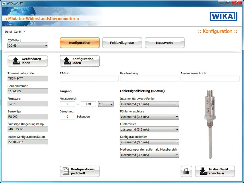
EN Operating instructions model TR34 (Ex i)                       Page      3 - 46

DE Betriebsanleitung Typ TR34 (Ex i)                              Seite    47 - 87

   Further languages can be found at www.wika.com.

   © 11/2014 WIKA Alexander Wiegand SE & Co. KG
   All rights reserved. / Alle Rechte vorbehalten.
   WIKA® is a registered trademark in various countries.
   WIKA® ist eine geschützte Marke in verschiedenen Ländern.

   Prior to starting any work, read the operating instructions!
                                                                                       14073822.05 04/2018 EN/DE

   Keep for later use!

   Vor Beginn aller Arbeiten Betriebsanleitung lesen!
   Zum späteren Gebrauch aufbewahren!

    2                                  WIKA operating instructions model TR34 (Ex i)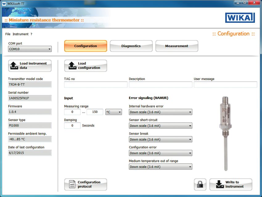
Contents

                            Contents                                                                                                 EN

                            1. General information                                                                               5
                            2. Safety                                                                                            7
                               2.1    Intended use  .  .  .  .  .  .  .  .  .  .  .  .  .  .  .  .  .  .  . 7
                               2.2    Personnel qualification  .  .  .  .  .  .  .  .  .  .  .  .  .  .  .  . 8
                               2.3    Additional safety instructions for instruments per ATEX  .  .  .  .  . 9
                               2.4    Special hazards  .  .  .  .  .  .  .  .  .  .  .  .  .  .  .  .  .  . 9
                               2.5    Labelling, safety marks  .  .  .  .  .  .  .  .  .  .  .  .  .  .  . 12
                            3. Specifications                                                                                   13
                            4. Design and function                                                                              18
                               4.1    Description  .  .  .  .  .  .  .  .  .  .  .  .  .  .  .  .  .  .  . 18
                               4.2    Dimensions in mm  .  .  .  .  .  .  .  .  .  .  .  .  .  .  .  .  . 19
                               4.3    Scope of delivery  .   .   .   .   .   .   .   .   .   .   .   .   .   .   .   .   .  20
                            5. Transport, packaging and storage                                                                 21
                               5.1    Transport  .   .   .   .   .   .   .   .   .   .   .   .   .   .   .   .   .   .   .   .  21
                               5.2    Packaging   .   .   .   .   .   .   .   .   .   .   .   .   .   .   .   .   .   .   . 21
                               5.3    Storage  .   .   .   .   .   .   .   .   .   .   .   .   .   .   .   .   .   .   .   . 21
                            6. Commissioning, operation                                                                         22
                               6.1 Mounting  .   .   .   .   .   .   .   .   .   .   .   .   .   .   .   .   .   .   .      .  22
                                  6.1.1 Tightening torques for compression fittings  .  .  .  .  .  .                         . 23
                                  6.1.2 Tightening torque for the M12 mating connector or the M12
                                        adapter  .   .   .   .   .   .   .   .   .   .   .   .   .   .   .   .   .   .      .  23
                               6.2 Electrical connection  .   .   .   .   .   .   .   .   .   .   .   .   .   .   .         .  24
                               6.3 Behaviour of the 4 ... 20 mA electrical output signal  .  .  .  .  .                       . 27
                            7. Configuration                                                                                    28
14073822.05 04/2018 EN/DE

                            8. Configuration software WIKAsoft-TT                                                               29
                               8.1    Starting the software  .   .   .   .   .   .   .   .   .   .   .   .   .   .   .   .      29
                               8.2    Configuration procedure  .  .  .  .  .  .  .  .  .  .  .  .  .  .  .                      30
                               8.3    Fault diagnosis  .   .   .   .   .   .   .   .   .   .   .   .   .   .   .   .   .   .    30
                               8.4    Measured values  .  .  .  .  .  .  .  .  .  .  .  .  .  .  .  .  .                        30
                               8.5    Configure several instruments identically  .   .   .   .   .   .   .   .   .              30

                            WIKA operating instructions model TR34 (Ex i)                                                        3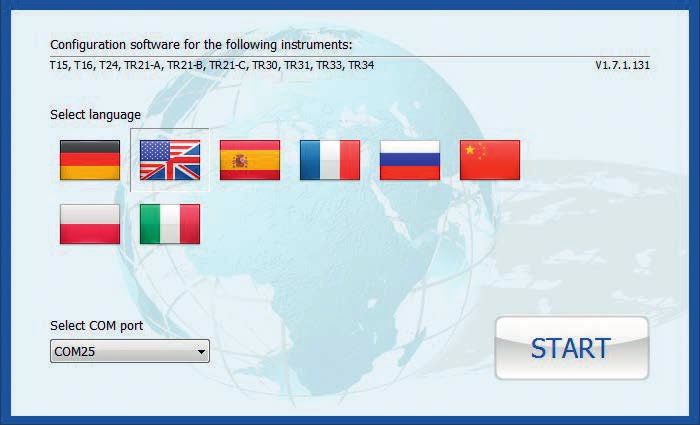
Contents
9. Connecting PU-548 programming unit 31
EN 10. Information on mounting and operation in hazardous areas 31
10.1 General information on explosion protection . . . . . . . . 31
10.1.1 Special conditions of use (X conditions) . . . . . . . . 34
10.1.2 Ex marking, temperature class classification and ambient
temperatures . . . . . . . . . . . . . . . . . 35
10.2 Overview of the temperature zones . . . . . . . . . . . 37
10.3 Mounting examples in hazardous areas . . . . . . . . . 38
11. Calculation examples for self-heating at the thermowell tip 39
11.1 Example calculation . . . . . . . . . . . . . . . . 39
12. Maintenance and cleaning 40
12.1 Maintenance . . . . . . . . . . . . . . . . . . . 40
12.2 Cleaning . . . . . . . . . . . . . . . . . . . . 40
13. Faults 41
14. Dismounting, return and disposal 42
14.1 Dismounting . . . . . . . . . . . . . . . . . . . 42
14.2 Return . . . . . . . . . . . . . . . . . . . . . 42
14.3 Disposal . . . . . . . . . . . . . . . . . . . . 43
Appendix 1: CSA control drawing 44
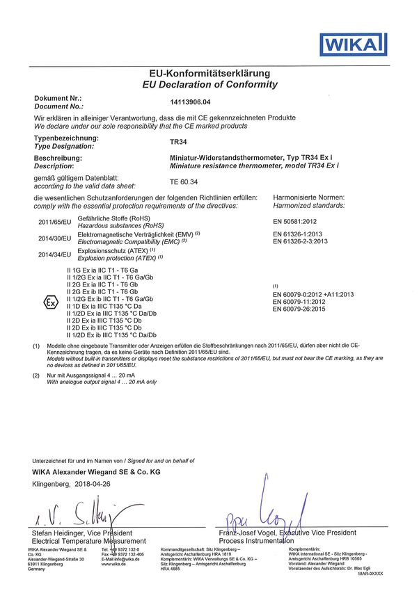
Appendix 2: EU declaration of conformity 46
Declarations of conformity can be found online at www.wika.com.
14073822.05 04/2018 EN/DE
4 WIKA operating instructions model TR34 (Ex i)
1. General information

                            1. General information
                            ■■ The resistance thermometer described in the operating instructions
                                                                                                             EN
                              has been designed and manufactured using state-of-the-art
                              technology. All components are subject to stringent quality and
                              environmental criteria during production. Our management systems
                              are certified to ISO 9001 and ISO 14001.
                            ■■ These operating instructions contain important information on handling
                              the instrument. Working safely requires that all safety instructions and
                              work instructions are observed.
                            ■■ Observe the relevant local accident prevention regulations and
                              general safety regulations for the instrument's range of use.
                            ■■ The operating instructions are part of the product and must be kept
                              in the immediate vicinity of the instrument and readily accessible to
                              skilled personnel at any time.
                            ■■ Skilled personnel must have carefully read and understood the
                              operating instructions prior to beginning any work.
                            ■■ The manufacturer's liability is void in the case of any damage caused
                              by using the product contrary to its intended use, non-compliance
                              with these operating instructions, assignment of insufficiently qualified
                              skilled personnel or unauthorised modifications to the instrument.
                            ■■ The general terms and conditions contained in the sales
                              documentation shall apply.
                            ■■ Subject to technical modifications.

                            ■■ Further information:
                              - Internet address:           www.wika.de / www.wika.com
                              - Relevant data sheet:        TE 60.34
14073822.05 04/2018 EN/DE

                              - Application consultant:     Tel.: +49 9372 132-0
                                                            Fax: +49 9372 132-406
                                                            info@wika.de

                            WIKA operating instructions model TR34 (Ex i)                                5
1. General information

     Explanation of symbols

              WARNING!
EN            ... indicates a potentially dangerous situation that can result
              in serious injury or death, if not avoided.

               CAUTION!
               ... indicates a potentially dangerous situation that can result
               in light injuries or damage to equipment or the environment,
               if not avoided.

               Information
               ... points out useful tips, recommendations and information
               for efficient and trouble-free operation.

               DANGER!
               ... identifies hazards caused by electrical power. Should the
               safety instructions not be observed, there is a risk of serious
               or fatal injury.

              WARNING!
              ... indicates a potentially dangerous situation in the
              hazardous area that can result in serious injury or death, if
              not avoided.

              WARNING!
              ... indicates a potentially dangerous situation that can result
              in burns, caused by hot surfaces or liquids, if not avoided.
                                                                                  14073822.05 04/2018 EN/DE

     6                            WIKA operating instructions model TR34 (Ex i)
1. General information / 2. Safety
Abbreviations
2-wire The lead resistance is recorded as an error in the measurement.
3-wire With a cable length of 30 m or longer, measuring deviations can EN
occur.
4-wire The lead resistance can be ignored.
2. Safety
WARNING!
Before installation, commissioning and operation, ensure
that the appropriate resistance thermometer has been
selected in terms of measuring range, design, specific
measuring conditions and appropriate wetted parts' materials
(corrosion).
Non-observance can result in serious injury and/or damage
to the equipment.
Further important safety instructions can be found in the
individual chapters of these operating instructions.
2.1 Intended use
The model TR34 resistance thermometer is used as a general-
purpose thermometer for the measurement of temperatures from
-50 … +150 °C or -58 ... + 302 °F (without neck tube) and -50 … +250 °C
or -58 ... +482 °F (with neck tube) in liquid and gaseous media. It can
be used for pressures up to 140 bar with 3 mm sensor diameter and
up to 270 bar with 6 mm sensor diameter, depending on the instrument
version. The thermometer is designed intrinsically safe for use in
14073822.05 04/2018 EN/DE
hazardous areas.
The instrument has been designed and built solely for the intended use
described here, and may only be used accordingly.
WIKA operating instructions model TR34 (Ex i) 72. Safety
The technical specifications contained in these operating instructions
must be observed. Improper handling or operation of the instrument
outside of its technical specifications requires the instrument to be taken
EN out of service immediately and inspected by an authorised WIKA service
engineer.
If the instrument is transported from a cold into a warm environment, the
formation of condensation may result in instrument malfunction. Before
putting it back into operation, wait for the instrument temperature and the
room temperature to equalise.
The manufacturer shall not be liable for claims of any type based on
operation contrary to the intended use.
2.2 Personnel qualification
WARNING!
Risk of injury should qualification be insufficient!
Improper handling can result in considerable injury and
damage to equipment.
■■ The activities described in these operating instructions
may only be carried out by skilled personnel who have the
qualifications described below.
■■ Keep unqualified personnel away from hazardous areas.
Skilled electrical personnel
Skilled electrical personnel are understood to be personnel who,
based on their technical training, know-how and experience as well
as their knowledge of country-specific regulations, current standards
and directives, are capable of carrying out work on electrical systems
and independently recognising and avoiding potential hazards. The
skilled electrical personnel have been specifically trained for the work
14073822.05 04/2018 EN/DE
environment they are working in and know the relevant standards and
regulations. The skilled electrical personnel must comply with current
legal accident prevention regulations.
Special operating conditions require further appropriate knowledge, e.g.
of aggressive media.
8 WIKA operating instructions model TR34 (Ex i)2. Safety
2.3 Additional safety instructions for instruments per ATEX
WARNING!
Follow the requirements of the ATEX directive. EN
Additionally the specifications of the respective national
regulations concerning Ex usage (e.g. EN 60079-10 and
EN 60079-14) apply.
Non-observance of these instructions and their contents may
result in the loss of explosion protection.
■■ The responsibility for classification of zones lies with the plant
operator and not the manufacturer/supplier of the equipment.
■■ The plant operator guarantees, and is solely responsible, that all
thermometers in use are identifiable with respect to all safety-relevant
characteristics. Damaged thermometers may not be used.
■■ Electrical screening may only be grounded at one end, and outside of
the Ex area. Special cases are described in DIN EN 60079-14:2003.
■■ There must be a galvanic separation between the intrinsically safe
and the non-intrinsically safe electrical circuits.
2.4 Special hazards
WARNING!
Neither repairs nor structural modifications are permitted,
and any would void the guarantee and the certification.
WARNING!
Observe the information given in the applicable type
examination certificate and the relevant country-specific
regulations for installation and use in hazardous areas (e.g.
IEC 60079-14, NEC, CEC). Non-observance can result in
14073822.05 04/2018 EN/DE
serious injury and/or damage to the equipment.
For additional important safety instructions for instruments
with ATEX approval see chapter 2.3 “Additional safety
instructions for instruments per ATEX”.
WIKA operating instructions model TR34 (Ex i) 92. Safety
WARNING!
Substitution of components may impair intrinsic safety.
EN
WARNING!
For hazardous media such as oxygen, acetylene,
flammable or toxic gases or liquids, and refrigeration plants,
compressors, etc., in addition to all standard regulations,
the appropriate existing codes or regulations must also be
followed.
WARNING!
Protection from electrostatic discharge (ESD) required!
The proper use of grounded work surfaces and personal
wrist straps is required when working with exposed circuitry
(printed circuit boards), in order to prevent static discharge
from damaging sensitive electronic components.
To ensure safe working on the instrument, the operating
company must ensure
■■ that suitable first-aid equipment is available and aid is
provided whenever required.
■■ that the operating personnel are regularly instructed in all
topics regarding work safety, first aid and environmental
protection and know the operating instructions and in
particular, the safety instructions contained therein.
DANGER!
Danger to life caused by electric current
Upon contact with live parts, there is a direct danger to life.
■■ Electrical instruments may only be installed and
14073822.05 04/2018 EN/DE
connected by skilled electrical personnel.
■■ Operation using a defective power supply unit (e.g. short-
circuit from the mains voltage to the output voltage) can
result in life-threatening voltages at the instrument!
10 WIKA operating instructions model TR34 (Ex i)2. Safety
WARNING!
Residual media in dismounted instruments can result in a
risk to persons, the environment and equipment.
Take sufficient precautionary measures. EN
Do not use this instrument in safety or emergency stop
devices. Incorrect use of the instrument can result in injury.
Should a failure occur, aggressive media with extremely high
temperature and under high pressure or vacuum may be
present at the instrument.
14073822.05 04/2018 EN/DE
WIKA operating instructions model TR34 (Ex i) 112. Safety
2.5 Labelling, safety marks
Product labels (example)
EN
Model
Date of manufacture (Year-Month)
Approval-related data
Information on version (measuring element, output signal, measuring range...)
■■ Thermometer with transmitter and 4 ... 20 mA output signal
14073822.05 04/2018 EN/DE
■■ Thermometer with direct sensor output with Pt100 and Pt1000
Serial number, TAG no.
Before mounting and commissioning the instrument,
ensure you read the operating instructions!
12 WIKA operating instructions model TR34 (Ex i)3. Specifications
3. Specifications
Thermometer with transmitter and 4 ... 20 mA output signal EN
(model TR34-x-TT)
Temperature range Without neck tube -30 ... +150 °C (-22 ... +302 °F)
With neck tube -30 ... +250 °C (-22 ... +482 °F) 1)
Measuring element Pt1000
Connection method 2-wire
Tolerance value of the Class A
measuring element (per IEC 60751)
Measuring deviation of ±0.25 K
the transmitter (per IEC 60770)
Total measuring devia- Measuring deviation of the measuring element +
tion in accordance with the transmitter
IEC 60770
Measuring span Minimum 20 K, maximum 300 K
Basic configuration Measuring range 0 ... 150 °C (32 ... 302 °F),
other measuring ranges are adjustable
Analogue output 4 ... 20 mA, 2-wire
Linearisation Linear to temperature per IEC 60751
Linearisation error ±0.1 % 2)
Switch-on delay, electrical Max. 4 s (time before the first measured value)
Warming-up period After approx. 4 minutes, the instrument will
function to the specifications (accuracy) given in
the data sheet.
Current signals for error Configurable in accordance with NAMUR NE43
signalling downscale ≤ 3.6 mA
upscale ≥ 21.0 mA
Sensor short-circuit Not configurable, in accordance with
NAMUR NE43 downscale ≤ 3.6 mA
14073822.05 04/2018 EN/DE
Sensor current < 0.3 mA (self-heating can be ignored.)
Load RA RA ≤ (UB - 10 V) / 23 mA with RA in Ω and UB in V
Effect of load ±0.05 % / 100 Ω
Power supply UB DC 10 ... 30 V
WIKA operating instructions model TR34 (Ex i) 133. Specifications
Thermometer with transmitter and 4 ... 20 mA output signal
(model TR34-x-TT)
EN Max. permissible residual 10 % generated by UB < 3 % ripple of the output
ripple current
Power supply input Protected against reverse polarity
Power supply effect ±0.025 % / V (depending on the power supply)
Influence of the ambient 0.1 % of span / 10 K Ta
temperature
Electromagnetic EN 61326 emission (group 1, class B) and
compatibility (EMC) 4) interference immunity (industrial application) 3),
configuration at 20 % of the full measuring range
Temperature units Configurable °C, °F, K
Info data TAG no., description and user message can be
stored in transmitter
Configuration and Permanently stored
calibration data
Electrical connection M12 x 1 circular connector (4-pin)
Readings in % refer to the measuring span
1) The temperature transmitter should therefore be protected from temperatures over 85 °C (185 °F).
2) ±0.2 % for measuring ranges with a lower limit less than 0 °C (32 °F)
3) Use resistance thermometers with shielded cable, and ground the shield on at least one end
of the lead, if the lines are longer than 30 m or leave the building. The instrument must be
operated grounded.
4) During transient interferences (e.g. burst, surge, ESD) take into account an increased
measuring deviation of up to 2 %.
14073822.05 04/2018 EN/DE
14 WIKA operating instructions model TR34 (Ex i)3. Specifications
Thermometer with direct sensor output with Pt100
(model TR34-x-Px) and Pt1000 (model TR34-x-Sx)
Temperature range EN
■■ Class A Without neck tube -30 ... +150 °C (-22 ... +302 °F)
With neck tube -30 ... +250 °C (-22 ... +482 °F)
■■ Class B Without neck tube -50 ... +150 °C (-58 ... +302 °F)
With neck tube -50 ... +250 °C (-58 ... +482 °F)
Temperature at the connector Max. 85 °C (185 °F)
Measuring element ■■ Pt100 (measuring current: 0.1 ... 1.0 mA)
■■ Pt1000 (measuring current: 0.1 ... 0.3 mA)
Connection method ■■ 2-wire
■■ 3-wire
■■ 4-wire
Tolerance value of the ■■ Class A
measuring element per ■■ Class B at 2-wire
IEC 60751
Electrical connection M12 x 1 circular connector (4-pin)
For detailed specifications for Pt sensors, see Technical information IN 00.17 at
www.wika.com.
Case
Material Stainless steel
Ingress protection
■■ Case with connected connector 5) IP67 and IP69 per IEC/EN 60529,
IP69K per ISO 20653
■■ Coupler connector, not connected IP67 per IEC/EN 60529
Weight in kg approx. 0.2 ... 0.7 (depending on
version)
Dimensions see “Dimensions in mm”
14073822.05 04/2018 EN/DE
5) The stated ingress protection only applies when plugged in using mating connectors that have
the appropriate ingress protection.
WIKA operating instructions model TR34 (Ex i) 153. Specifications
Ambient conditions
Ambient temperature range
■■ Model TR34-x-TT -40 ... +85 °C (-40 ... +185 °F)
EN
■■ Models TR34-x-Px, TR34-x-Sx -50 ... +85 °C (-58 ... +185 °F)
Storage temperature range -40 ... +85 °C (-40 ... +185 °F)
Climate class per IEC 60654-1
■■ Model TR34-x-TT Cx (-40 ... +85 °C or -40 ... +185 °F,
5 ... 95 % r. h.)
■■ Models TR34-x-Px, TR34-x-Sx Cx (-50 ... +85 °C or -58 ... +185 °F,
5 ... 95 % r. h.)
Maximum permissible humidity r. h. 100 %, condensation allowed
per IEC 60068-2-30 var. 2
Maximum operating pressure 6) 7) 140 bar with 3 mm sensor diameter
270 bar with 6 mm sensor diameter
Vibration resistance per IEC 60751 10 ... 2,000 Hz, 20 g 6)
Shock resistance per IEC 60068-2-27 50 g, 6 ms, 3 axis, 3 faces, 3 times
for each face
Salt fog IEC 60068-2-11
6) Dependent on the instrument version
7) Reduced operating pressure when using a compression fitting:
Stainless steel: max. 100 bar
PTFE: max. 8 bar
Patents, property rights
M12 x 1 adapter to DIN EN 175301-803 angular No. 001370985
connector
14073822.05 04/2018 EN/DE
16 WIKA operating instructions model TR34 (Ex i)3. Specifications
Safety-related maximum values for the current loop circuit
■■ Thermometer with transmitter and 4 ... 20 mA output signal
(model TR34-x-TT) EN
Parameters Hazardous gas Hazardous dust
atmosphere atmosphere
Terminals +/- +/-
Voltage Ui DC 30 V DC 30 V
Current li 120 mA 120 mA
Power Pi 800 mW 750/650/550 mW
Effective internal capacitance Ci 29.7 nF 29.7 nF
Effective internal inductance Li negligible negligible
Maximum self-heating at the 15 K 15 K
sensor or thermowell tip
■■ Thermometer with direct sensor output with Pt100
(model TR34-x-Px) and Pt1000 (model TR34-x-Sx)
Parameters Hazardous gas Hazardous dust
atmosphere atmosphere
Terminals 1-4 1-4
Voltage Ui DC 30 V DC 30 V
Current li 550 mA 250 mA
Power Pi 1,500 mW 750/650/550 mW
Effective internal capacitance Ci negligible negligible
Effective internal inductance Li negligible negligible
Maximum self-heating at the (Rth) = 335 K/W (Rth) = 335 K/W
sensor or thermowell tip
14073822.05 04/2018 EN/DE
For further specifications see WIKA data sheet TE 60.34 and the order
documentation.
WIKA operating instructions model TR34 (Ex i) 174. Design and function
4. Design and function
EN 4.1 Description
The model TR34 resistance thermometer consists of a thermowell with
a fixed process connection and is screwed directly into the process.
It is designed to be impact and vibration resistant and all electrical
components are protected against humidity (IP67 or IP69K). The
vibration resistance conforms to IEC 60751 (20 g, dependent on the
instrument version). The impact resistance of all versions meets the
requirements of IEC 60751. Ensure that mechanical loads on the
connector are minimised, especially in case of increased ambient
temperatures or strong vibration loads.
The electrical connection is made with an M12 x 1 circular connector.
The following accessories may be used:
Accessories Order no.
M12 x 1 adapter to DIN EN 175301-803-A angular connector
■■ for Pt100 and Pt1000 14061115
■■ for 4 ... 20 mA 14069503
Angular connector DIN EN 175301-803-A 11427567
Sealing for angular connector, EPDM, brown 11437902
Connection cable with moulded M12 x 1 connector
■■ Cable socket straight, 4-pin, ingress protection IP67 2m 14086880
- Temperature range -20 ... +80 °C 5m 14086883
■■ Angled socket, 4-pin, ingress protection IP67 2m 14086889
- Temperature range -20 ... +80 °C 5m 14086891
14073822.05 04/2018 EN/DE
18 WIKA operating instructions model TR34 (Ex i)4. Design and function
4.2 Dimensions in mm
■■ Process connection with parallel threads (or without process
connection) EN
without neck tube with neck tube
with compression
fitting
140069565.02
without
process connection
X
X
X
X
Legend:
A (U1) Insertion length
1) At a process temperature of > 150 °C (302 °F), N (MH) Neck length
a neck length N (MH) of 70 mm is necessary, X Height process connection
otherwise N (MH) selectable (55, 65 or 70 mm). Ød Sensor diameter
Thread Height process connection X
G 1/2 11
G 3/8 11
G 1/4 10
M12 11
M20 11
14073822.05 04/2018 EN/DE
WIKA operating instructions model TR34 (Ex i) 194. Design and function
■■ Process connection with tapered thread
without neck tube with neck tube
EN with compression fitting
140069565.02
X
Legend:
A (U2) Insertion length
1) At a process temperature of > 150 °C (302 °F), N (MH) Neck length
a neck length N (MH) of 70 mm is necessary, X Height process connection
otherwise N (MH) selectable (55, 65 or 70 mm). Ød Sensor diameter
Thread Height process connection X
1/4 NPT 15
1/2 NPT 19
4.3 Scope of delivery
Cross-check scope of delivery with delivery note.
14073822.05 04/2018 EN/DE
20 WIKA operating instructions model TR34 (Ex i)5. Transport, packaging and storage
5. Transport, packaging and storage
5.1 Transport
EN
Check the instrument for any damage that may have been caused by
transport.
Obvious damage must be reported immediately and damaged
instruments must not be used.
5.2 Packaging
Do not remove packaging until just before mounting.
Keep the packaging as it will provide optimum protection during transport
(e.g. change in installation site, sending for repair).
5.3 Storage
Permissible conditions at the place of storage:
■■ Storage temperature: -40 ... +85 °C (-40 ... +185 °F)
■■ Humidity: 5 ... 95 % r. h.
Avoid exposure to the following factors:
■■ Direct sunlight or proximity to hot objects
■■ Mechanical vibration, mechanical shock (putting it down hard)
■■ Soot, vapour, dust and corrosive gases
Store the instrument in its original packaging in a location that fulfils the
conditions listed above. If the original packaging is not available, pack
and store the instrument as described below:
1. Wrap the instrument in an antistatic plastic film.
2. Place the instrument, along with the shock-absorbent material, in the
packaging.
3. If stored for a prolonged period of time (more than 30 days), place a
bag containing a desiccant inside the packaging.
14073822.05 04/2018 EN/DE
WARNING!
Before storing the instrument (following operation), remove
any residual media. This is of particular importance if
the medium is hazardous to health, e.g. caustic, toxic,
carcinogenic, radioactive, etc.
WIKA operating instructions model TR34 (Ex i) 216. Commissioning, operation
6. Commissioning, operation
WARNING!
EN
Avoid putting any mechanical loading on the electrical
connections and on the cases. Connections must only be
opened once the instrument has been depressurised and
has cooled down.
Maximum permissible temperatures:
■■ At case with transmitter: 85 °C (185 °F)
■■ Class A:
Without neck tube -30 ... +150 °C (-22 ... +302 °F)
With neck tube -30 ... +250 °C (-22 ... +482 °F)
■■ Class B:
Without neck tube -50 ... +150 °C (-58 ... +302 °F)
With neck tube -50 ... +250 °C (-58 ... +482 °F)
6.1 Mounting
These resistance thermometers are designed for screw-fitting directly
into the process. The insertion length, along with the flow velocity and
viscosity of the process media, may reduce the max. loading on the
thermowell.
The case must be grounded against electromagnetic fields and
electrostatic discharge. It is not necessary to connect the case
separately to the equipotential bonding system, provided that it has a
fixed and secure contact to the metallic vessel, its components or pipes,
and that these are connected to the equipotential bonding system.
When there is a non-metallic contact with the vessel, or with its structural
components or piping, all projecting, electrically conducting thermometer
14073822.05 04/2018 EN/DE
components in the hazardous area must be provided with equipotential
bonding.
WARNING!
Neither repairs nor structural modifications are permitted,
and any would void the guarantee and the certification.
22 WIKA operating instructions model TR34 (Ex i)6. Commissioning, operation
Installation examples
EN
Insertion length A
Installation on pipes
a on elbows
b in smaller pipe, inclined
c perpendicular to flow direction
For information on tapped holes, refer to DIN 3852 or for NPT threads to
ANSI B 1.20.
6.1.1 Tightening torques for compression fittings
Sealing Rotation Max. pressure in bar
Stainless steel ferrule 1 ¼ ... 1 ½ 100
Stainless steel compression ring 1 ¼ ... 1 ½ 100
PTFE ferrule 1 ¼ ... 1 ½ 8
6.1.2 Tightening torque for the M12 mating connector or the M12
adapter
14073822.05 04/2018 EN/DE
Select a tightening torque of 0.6 Nm.
WIKA operating instructions model TR34 (Ex i) 236. Commissioning, operation
6.2 Electrical connection
The electrical connection is made via a M12 x 1 (4-pin) circular
connector.
EN
■■ Output signal Pt100 and Pt1000 (standard)
Alternative pin assignments possible.
For further
4 ... 20 mA
information see order documentation.
Accessories:
mA M12 x 1 Pt adapter to DIN EN 175301-803 angular connector
M12 x 1 connector Angular connector
14073822.05 04/2018 EN/DE
24 WIKA operating instructions model TR34 (Ex i)6. Commissioning, operation
■■ Output signal 4 ... 20 mA (standard)
EN
Pin Signal Description
1 L+ 10 ... 30 V
2 VQ not connected
3 L- 0V
4 C not connected
Alternative pin assignments possible.
For further information see order documentation.
Accessories: M12 x 1 transmitter adapter to DIN EN 175301-803
angular connector
M12 x 1 connector Angular connector
4 ... 20 mA
mA
Pin assignment angular connector
Pin Signal Description
14073822.05 04/2018 EN/DE
1 L+ 10 ... 30 V
2 L- 0V
3 VQ not connected
4 C not connected
WIKA operating instructions model TR34 (Ex i) 256. Commissioning, operation
DANGER!
Danger to life caused by electric current
Upon contact with live parts, there is a direct danger to life.
EN ■■ The instrument may only be installed and mounted by
skilled personnel.
■■ Operation using a defective power supply unit (e.g. short-
circuit from the mains voltage to the output voltage) can
result in life-threatening voltages at the instrument!
■■ Carry out mounting work only with power disconnected.
This is protection class 3 equipment for connection at low voltages,
which are separated from the power supply or voltages of greater than
AC 50 V or DC 120 V. Preferably, a connection to an SELV or PELV circuit
is recommended; alternatively protective measures from HD 60346-4-41
(DIN VDE 0100-410).
Alternatively for North America
The connection can be made in line with “Class 2 Circuits” or “Class 2
Power Units” in accordance with CEC (Canadian Electrical Code) or
NEC (National Electrical Code).
Load diagram
The permissible load depends on the loop supply voltage. For
communication with the instrument with programming unit PU-548, a
max. load of 350 Ω is admissible.
833
583
14073822.05 04/2018 EN/DE
Load RA in Ω
0 10 24 30
Voltage UB in V
26 WIKA operating instructions model TR34 (Ex i)6. Commissioning, operation
6.3 Behaviour of the 4 ... 20 mA electrical output signal
■■ Sensor break and short circuit
Sensor break or short circuit are signalled after positive detection EN
(after approx. 1 second). If this fault condition has been caused by
a malfunction, then a relevant measurement signal must exist for
approx. 1 second in order to return to measuring mode. From the
time of the error detection up to the error signalling, the last relevant
measured value will be delivered on the current loop.
Therefore, in the event of a “true” sensor break or short-circuit, this
is also signalled permanently. In the event of a “false” sensor break
or short-circuit, the transmitter has the possibility of reverting to
measuring mode.
■■ Medium temperature outside the span
If the media temperature exceeds that configured within the
transmitter, the transmitter will operate in a linear fashion within the
following limits: 3.8 mA (MRS); 20.5 mA (MRE). If these limits are
exceeded, then an error will be signalled.
■■ Hysteresis on return to the measuring span
After the linear error limits have been exceeded, on return to the
measuring span, a hysteresis of 0.1 mA must be passed. This
hysteresis prevents the transmitter from jumping back and forth
between error and measuring mode.
3.8 mA 4 mA 20 mA 20.5 mA
Error 3.8 ... Error
signalling 4 mA
4 ... 20 mA 20 ... 20.5 mA
signalling
14073822.05 04/2018 EN/DE
Measuring mode
Error signalling Error signalling
3.9 mA 20.4 mA
Error limits and permissible measuring range
WIKA operating instructions model TR34 (Ex i) 277. Configuration
7. Configuration
Configuration is carried out using a USB interface with a PC via the
EN model PU-548 programming unit (accessories, order no. 14231581). The
connection with the thermometer is made via the appropriate adapter
cable. (Accessories: M12 x 1 circular connector, order no. 14003193)
Measuring range, damping, error signalling, TAG no. and other
parameters can be adjusted (see configuration software).
■■ Easy to use
■■ LED status display
■■ Compact design
■■ No further voltage supply is needed for
either the programming unit or for the
transmitter
(replaces programming unit model PU-448)
The measuring range is configurable between -50 ... +250 °C
(-58 ... +482 °F). The configuration software checks the desired
measuring range and will only accept permissible values. Intermediate
values are configurable - the smallest increment is 0.1 °C or 0.1 °F. The
thermometers are delivered configured to customer specifications within
the configurable limits.
Please note:
The measuring range of the thermometer is limited by the application
range of the measuring element, not by the setting range of the
transmitter.
Maximum permissible temperatures:
■■ At case with transmitter: 85 °C (185 °F)
14073822.05 04/2018 EN/DE
■■ Class A:
Without neck tube -30 ... +150 °C (-22 ... +302 °F)
With neck tube -30 ... +250 °C (-22 ... +482 °F)
■■ Class B:
Without neck tube -50 ... +150 °C (-58 ... +302 °F)
With neck tube -50 ... +250 °C (-58 ... +482 °F)
28 WIKA operating instructions model TR34 (Ex i)8. Configuration software WIKAsoft-TT
8. Configuration software WIKAsoft-TT
For installation please follow the instructions of the installation routine.
EN
8.1 Starting the software
Start the configuration software by double-clicking on the WIKAsoft-TT
icon.
After starting the software, the
language can be changed, via
the selection of the appropriate
country‘s flag.
The selection of the COM port is
made automatically.
After the connection of a transmitter
(using the PU-548), on pressing the “Start” button, the configuration
interface is loaded.
The configuration interface can only be loaded when an
instrument is connected.
14073822.05 04/2018 EN/DE
WIKA operating instructions model TR34 (Ex i) 298. Configuration software WIKAsoft-TT
8.2 Configuration procedure
Steps 1 and 2 are carried out automatically when starting the software.
1. “Loading the instrument data”
EN 2. “Loading configuration”
3. [optional] Cancel write protection (“key” symbol at the bottom right)
4. Change the required parameters
→ Sensor/Measuring range/Error signalling etc.
5. “Save to the instrument”
6. [optional] Activate write protection
7. [optional] Print configuration protocol
8. [optional] Test: “Loading configuration” → checking the configuration
8.3 Fault diagnosis
Here, in the event of an “error detected by the transmitter”, the error
message is displayed.
Examples: Sensor break, permitted highest temperature exceeded, etc.
In normal operation, “No fault - No maintenance requirement” is
displayed here.
8.4 Measured values
Line recorder - Here the measured value progression is represented in
the format of a chart recorder with a constant sampling rate in a defined
time interval (180 seconds) and a variable temperature axis.
The display purely serves as a functional check and for information.
An export of the data is not possible.
8.5 Configure several instruments identically
■■ First instrument
1. “Loading configuration”
2. [optional] Cancel write protection (“key” symbol at the bottom right)
3. Change the required parameters
4. “Save to the instrument”
14073822.05 04/2018 EN/DE
5. [optional] Activate write protection
■■ All subsequent instruments
1. “Loading the instrument data”
2. [optional] Cancel write protection
3. [optional] Change the required parameters, e. g. TAG number
4. “Save to the instrument”
5. [optional] Activate write protection
30 WIKA operating instructions model TR34 (Ex i)9. Connecting PU-548 ... / 10. Information on ...
9. Connecting PU-548 programming unit
Connection PU-548 ↔ adapter cable with M12 connector EN
14004919.01
TR34
(predecessor, programming unit model PU-448, also compatible)
10. Information on mounting and operation in
hazardous areas
14073822.05 04/2018 EN/DE
10.1 General information on explosion protection
The requirements of the ATEX directive must be followed.
Additionally the specifications of the respective national
regulations concerning Ex usage (e.g. IEC/EN 60079-10 and
IEC/EN 60079-14) apply.
WIKA operating instructions model TR34 (Ex i) 3110. Information on mounting and operation in ...
■■ For the installation of the thermometers, only components (e.g.
cables, cable glands, etc.) permitted for “intrinsic safety” may be used.
■■ For grounding the conductive screen, follow the specifications of
EN
IEC/EN 60079-14.
■■ The temperature resistance of the connecting cable must match the
permissible operating temperature of the cases.
For ambient temperatures above 60 °C, heat-resistant connecting
cable must be used (see table in chapter 4 “Design and function”).
■■ Mounting within metallic enclosures:
The case must be grounded against electromagnetic fields and
electrostatic discharge. It does not have to be connected separately
to the equipotential bonding system. It is sufficient if the metallic
thermowell has a solid and secured contact with the metallic vessel or
its structural components or pipelines, so long as these components
are connected to the equipotential bonding system.
■■ Mounting within non-metallic enclosures:
- Ground the cable shield at one end, preferably in the safe, and so
non-Ex, area (EN 60079-14) . For instruments with cable output,
the shield is connected to the case. The simultaneous connection
of the case and the cable shield to ground is only permitted if any
accidental energisation between the shield connection (e.g. at the
power supply) and the case can be excluded (see EN 60079-14).
- Power the resistance thermometer via an intrinsically safe current
circuit (Ex ia).
- Both the effective internal capacitance and inductance must be
considered
- Fine-gauge wires with bare ends must be finished with end splices
(cable preparation).
- With cables for use in zone 1 and 2, the test voltage between
conductor/ground, conductor/screen, screen/ground must be
> AC 500 V.
14073822.05 04/2018 EN/DE
■■ Neither repairs nor structural modifications are permitted, and any
would void the guarantee and the respective certification.
■■ The manufacturer shall not be responsible for constructional
modifications after delivery of the instruments.
32 WIKA operating instructions model TR34 (Ex i)10. Information on mounting and operation in ...
A) The responsibility for classification of zones lies with the plant
operator and not the manufacturer/supplier of the equipment.
B) The plant operator guarantees, and is solely responsible, that all EN
thermometers in use are identifiable with respect to all safety-relevant
characteristics. Damaged thermometers may not be used. Repairs
may only be carried out by authorised and qualified personnel.
Repairs may only be completed using original spare parts from the
original supplier; otherwise the requirements of the approval are not
fulfilled.
The manufacturer shall not be responsible for constructional
modifications after delivery of the instruments.
C) If a component of electrical equipment, on which the explosion
protection depends, is repaired, then the electrical equipment may
only be put back into use, after an authorised expert has stated that
it corresponds to the fundamental characteristics of the requirements
for explosion protection. In addition this expert must provide a
certificate for this and provide the equipment with a test mark.
D) Item C) shall not apply if the component was repaired by the
manufacturer in accordance with the requirements and regulations.
E) When ordering spare parts, the parts that are to be replaced must be
specified exactly:
■■ Ignition protection type (here Ex i)
■■ Approval no.
■■ Order no.
■■ Manufacturing no.
■■ Order item
14073822.05 04/2018 EN/DE
WIKA operating instructions model TR34 (Ex i) 3310. Information on mounting and operation in ...
10.1.1 Special conditions of use (X conditions)
1. Thermal backflow from the process, that exceeds the permissible
ambient temperature of the transmitter or the cases, must not be
EN allowed to occur and must be prevented by the installation of suitable
heat insulation or a neck tube of suitable length.
2. The wall thickness is greater than 0.2 mm and less than 1 mm. Thus
the instruments must not be subjected to ambient stresses that may
have an adverse effect on the partition wall. Alternatively, a thermowell
of suitable minimum wall thickness may be used.
3. When using a thermowell/neck tube, the overall instrument
must be designed such that it allows installation in a way that
results in a sufficiently tight clearance (IP67) or a flameproof gap
(IEC/EN 60079-1) towards the less hazardous area.
4. The ambient temperature range (Ta) for variants with optional
connection cable with moulded M12 x 1 connector is limited to
-20 ... +80 °C.
5. The ambient temperature range (Ta) for variants with optional
EN 175301 M12 adapters is limited to -40 ... +85 °C.
14073822.05 04/2018 EN/DE
34 WIKA operating instructions model TR34 (Ex i)10. Information on mounting and operation in ...
10.1.2 Ex marking, temperature class classification and ambient
temperatures
For applications without transmitters (models TR34-x-Px and
TR34-x-Sx) that require Group II instruments (potentially explosive gas EN
atmospheres), the following temperature class classification and ambient
temperature ranges apply:
Table 1
Marking Temperature Ambient Max. surface temperature
class temperature (Tmax) at the sensor or
range (Ta) thermowell tip
II 1G Ex ia IIC T6 -50 ... +80 °C TM (medium temperature) +
T1 - T6 Ga T5 -50 ... +85 °C self-heating
II 1/2G Ex ia IIC T4 -50 ... +85 °C Pay attention to the specific
T1 - T6 Ga/Gb conditions for safe use (see
T3 -50 ... +85 °C
II 2G Ex ia IIC chapter 10.1.1 “Special
T2 -50 ... +85 °C conditions of use (X
T1 - T6 Gb
T1 -50 ... +85 °C conditions)”).
For applications requiring instruments of equipment Group II (potentially
explosive dust atmospheres), the following surface temperatures and
ambient temperature ranges apply:
Table 2
Marking Power Pi Ambient Max. surface temperature
temperature (Tmax) at the sensor or
range (Ta) thermowell tip
II 1D Ex ia IIIC 750 mW -50 ... +40 °C TM (medium temperature) +
T135 °C Da self-heating
II 1/2D Ex ia IIIC 650 mW -50 ... +70 °C Pay attention to the specific
14073822.05 04/2018 EN/DE
T135 °C Da/Db conditions for safe use (see
II 2D Ex ia IIIC chapter 10.1.1 “Special
550 mW -50 ... +85 °C conditions of use (X
T135 °C Db
conditions)”).
WIKA operating instructions model TR34 (Ex i) 3510. Information on mounting and operation in ...
For applications with transmitters (TR34-x-TT) that require Group II
instruments (potentially explosive gas atmospheres), the following
temperature class classification and ambient temperature ranges apply:
EN
Table 3
Hazardous gas Temperature Ambient Max. surface temperature
atmosphere class temperature (Tmax) at the sensor or
range (Ta) thermowell tip
II 1G Ex ia IIC T6 -40 ... +45 °C TM (medium temperature) +
T1 - T6 Ga T5 -40 ... +60 °C self-heating (15 K)
II 1/2G Ex ia IIC T4 -40 ... +85 °C Pay attention to the specific
T1 - T6 Ga/Gb conditions for safe use (see
T3 -40 ... +85 °C
II 2G Ex ia IIC chapter 10.1.1 “Special
T2 -40 ... +85 °C conditions of use (X
T1 - T6 Gb
T1 -40 ... +85 °C conditions)”).
For applications requiring instruments of equipment Group II (potentially
explosive dust atmospheres), the following surface temperatures and
ambient temperature ranges apply:
Table 4
Hazardous dust Power Pi Ambient Max. surface temperature
atmosphere temperature (Tmax) at the sensor or
range (Ta) thermowell tip
II 1D Ex ia IIIC 750 mW -40 ... +40 °C TM (medium temperature) +
T135 °C Da self-heating (15 K)
II 1/2D Ex ia IIIC 650 mW -40 ... +70 °C Pay attention to the specific
T135 °C Da/Db conditions for safe use (see
550 mW -40 ... +85 °C chapter 10.1.1 “Special
II 2D Ex ia IIIC
T135 °C Db conditions of use (X
conditions)”).
14073822.05 04/2018 EN/DE
36 WIKA operating instructions model TR34 (Ex i)10. Information on mounting and operation in ...
For applications that require EPL Gb or Db, the instruments designated
as “ia” can also be used in type “ib” measuring circuits, with the same
connection parameters.
EN
Thus the entire measuring circuit (including the sensor circuit) is an “ib”
current circuit. Instruments that have been operated in a power supply
circuit of type “ib” cannot be re-used in a power supply circuit of type “ia”.
10.2 Overview of the temperature zones
with transmitter without transmitter with transmitter without transmitter
without neck tube without neck tube with neck tube with neck tube
14103751.01
Ta: -40 ... +85 °C Ta: -50 ... +85 °C
Ta: -40 ... +85 °C Ta: -50 ... +85 °C Ta: -40 ... +85 °C Ta: -50 ... +150 °C
Process Process Process Process
connection connection connection connection
Tprocess: -30 ... +150 °C Tprocess: -50 ... +150 °C Tprocess: -30 ... +250 °C Tprocess: -50 ... +250 °C
14073822.05 04/2018 EN/DE
WIKA operating instructions model TR34 (Ex i) 37EN
associated electrical
38
equipment
Intrinsically safe Intrinsically safe Intrinsically safe Intrinsically safe Intrinsically safe
supply or suitable supply or suitable supply or suitable supply or suitable supply or suitable
barrier barrier barrier barrier barrier
Safe area Safe area
Ex area Ex area
Zone 1, marking 1/2G
Zone 21, marking 1/2D
Process Process
Zone 0
Zone 20
fully in zone 0 or 20, marking 1G or 1D
fully in zone 1 or 21, marking 2G or 2D
connection connection welded
Separation of Ex zones
Process Process
10.3 Mounting examples in hazardous areas
connection connection
Ex area
14103747.01
10. Information on mounting and operation in ...
WIKA operating instructions model TR34 (Ex i)
14073822.05 04/2018 EN/DE11. Calculation examples for self-heating at the ...
11. Calculation examples for self-heating at the
thermowell tip
EN
11.1 Example calculation
Use at the partition to zone 0
The maximum possible temperature, Tmax, at the Ø 6 mm thermowell tip
with transmitter is being sought.
Tmax is obtained by adding the medium temperature and the
self-heating. The self-heating depends on the supplied power Po as well
as the thermal resistance Rth and is 15 K.
Example
Diameter: 6 mm
Medium temperature: TM = 150 °C
Temperature class T3 (200 °C) must not be exceeded
Self-heating: 15 K
Tmax = TM + self-heating: 150 °C + 15 °C = 165 °C
As safety margin for type-examined instruments (for T6 to T3), an
additional 5 °C must be subtracted from the 200 °C; hence 195 °C would
be permissible. This means that in this case temperature class T3 is not
exceeded.
Additional information:
Temperature class for T3 = 200 °C
Safety margin for type-tested instruments (for T6 to T3) 1) = 5 K
Safety margin for type-tested instruments (for T2 to T1) 1) = 10 K
1) IEC/EN 60079-0: 2012 Ch. 26.5.1
14073822.05 04/2018 EN/DE
WIKA operating instructions model TR34 (Ex i) 3912. Maintenance and cleaning
12. Maintenance and cleaning
12.1 Maintenance
EN
The resistance thermometers described here require absolutely no
maintenance and contain no components which could be repaired or
replaced.
12.2 Cleaning
CAUTION!
■■ Before cleaning the instrument, disconnect the electrical
connections.
■■ Clean the instrument with a moist cloth. This applies in
particular to thermometers with a case made of plastic
and cable sensors with plastic-insulated connecting
cable, to ensure that any risk of electrostatic discharge is
avoided.
■■ Electrical connections must not come into contact with
moisture.
■■ Wash or clean the dismounted instrument before returning
it, in order to protect persons and the environment from
exposure to residual media.
■■ Residual media in dismounted instruments can result in
a risk to persons, the environment and equipment. Take
sufficient precautionary measures.
For information on returning the instrument, see chapter 14.2
“Return”.
14073822.05 04/2018 EN/DE
40 WIKA operating instructions model TR34 (Ex i)13. Faults
13. Faults
Faults Causes Measures EN
No signal/line break Mechanical load too Replace the sensor with a
high or overtemperature suitable version
Erroneous measured Sensor drift caused by Replace the sensor with a
values overtemperature suitable version
Sensor drift caused by Analyse the medium
chemical attack
Erroneous measured Entry of moisture into Use the appropriate IP
values (too low) cable protection
Erroneous measured Wrong mounting The temperature-sensitive
values and response geometry, for example area of the sensor must
times too long mounting depth too be inside the medium, and
deep or heat dissipation surface measurements
too high must be ungrounded
Deposits on the Remove deposits
thermowell
Temporary or Cable break in Replace the sensor or use
intermittent connection cable or thicker conductor cross-
interruptions of the loose contact caused by section
measured value mechanical overload
signal
Corrosion Composition of the Analyse the medium
medium not as expected
or modified
Signal interference Stray currents caused Use of screened
by electric fields or earth connecting cables,
loops increase in the distance to
motors and power lines
Earth loops Elimination of potentials,
14073822.05 04/2018 EN/DE
use of galvanically
isolated transmitter supply
isolators or transmitters
WIKA operating instructions model TR34 (Ex i) 4113. Faults / 14. Dismounting, return and disposal
CAUTION!
If faults cannot be eliminated by means of the measures
listed above, the instrument must be shut down immediately,
EN and it must be ensured that signal is no longer present, and
it must be prevented from being inadvertently put back into
service. In this case, contact the manufacturer.
If a return is needed, follow the instructions given in chapter
14.2 “Return”.
14. Dismounting, return and disposal
WARNING!
Residual media in dismounted instruments can result in a
risk to persons, the environment and equipment.
Take sufficient precautionary measures.
14.1 Dismounting
WARNING!
Risk of burns!
Let the instrument cool down sufficiently before dismounting it!
During dismounting there is a risk of dangerously hot media
escaping.
Only disconnect the resistance thermometer once the system has been
depressurised!
14.2 Return
WARNING!
14073822.05 04/2018 EN/DE
Strictly observe the following when shipping the
instrument:
All instruments delivered to WIKA must be free from any kind
of hazardous substances (acids, bases, solutions, etc.).
42 WIKA operating instructions model TR34 (Ex i)14. Dismounting, return and disposal
When returning the instrument, use the original packaging or a suitable
transport packaging.
To avoid damage: EN
1. Wrap the instrument in an antistatic plastic film.
2. Place the instrument, along with the shock-absorbent material, in the
packaging.
Place shock-absorbent material evenly on all sides of the transport
packaging.
3. If possible, place a bag containing a desiccant inside the packaging.
4. Label the shipment as carriage of a highly sensitive measuring
instrument.
Information on returns can be found under the heading
“Service” on our local website.
14.3 Disposal
Incorrect disposal can put the environment at risk.
Dispose of instrument components and packaging materials in an
environmentally compatible way and in accordance with the country-
specific waste disposal regulations.
14073822.05 04/2018 EN/DE
WIKA operating instructions model TR34 (Ex i) 43EN
44
Intrinsically safe installation
Entity parameters TR21-*-W-*, TR31-*-W-*, TR34-W-*
Appendix 1: CSA control drawing
WIKA operating instructions model TR34 (Ex i)
14073822.05 04/2018 EN/DE14073822.05 04/2018 EN/DE
Nonincendive field wiring installation
NIFW parameters TR21-*-W-*, TR31-*-W-*, TR34-W-*
Intrinsic safety barrier not required. Vmax or Ui ≤ DC 30 V
TR* CSA or FM approved associated apparatus
Non-Incendive field wiring apparatus or associated nonincendive field firing apparatus
WIKA operating instructions model TR34 (Ex i)
Appendix 1: CSA control drawing
≥ ≥ ≥
≥ ≥ ≥ ≥
45
ENAppendix 2: EU declaration of conformity
EN
14073822.05 04/2018 EN/DE
46 WIKA operating instructions model TR34 (Ex i)Inhalt
Inhalt
1. Allgemeines 49 DE
2. Sicherheit 51
2.1 Bestimmungsgemäße Verwendung . . . . . . . . . . . 51
2.2 Personalqualifikation . . . . . . . . . . . . . . . . 52
2.3 Zusätzliche Sicherheitshinweise für Geräte nach ATEX . . . . 53
2.4 Besondere Gefahren . . . . . . . . . . . . . . . . 53
2.5 Beschilderung, Sicherheitskennzeichnungen . . . . . . . . 56
3. Technische Daten 57
4. Aufbau und Funktion 62
4.1 Beschreibung . . . . . . . . . . . . . . . . . . 62
4.2 Abmessungen in mm . . . . . . . . . . . . . . . . 63
4.3 Lieferumfang . . . . . . . . . . . . . . . . . . . 64
5. Transport, Verpackung und Lagerung 65
5.1 Transport . . . . . . . . . . . . . . . . . . . . 65
5.2 Verpackung . . . . . . . . . . . . . . . . . . . 65
5.3 Lagerung . . . . . . . . . . . . . . . . . . . . 65
6. Inbetriebnahme, Betrieb 66
6.1 Montage . . . . . . . . . . . . . . . . . . . . 66
6.1.1 Anzugsdrehmomente für Klemmverschraubungen . . . . 67
6.1.2 Anzugsdrehmoment für den M12-Gegenstecker oder
den M12-Adapter . . . . . . . . . . . . . . . 67
6.2 Elektrischer Anschluss . . . . . . . . . . . . . . . 68
6.3 Verhalten des elektrischen Ausgangssignals 4 ... 20 mA . . . . 71
7. Konfiguration 72
14073822.05 04/2018 EN/DE
8. Konfigurationssoftware WIKAsoft-TT 73
8.1 Starten der Software . . . . . . . . . . . . . . . . 73
8.2 Ablauf Konfiguration . . . . . . . . . . . . . . . . 74
8.3 Fehlerdiagnose . . . . . . . . . . . . . . . . . . 74
8.4 Messwerte . . . . . . . . . . . . . . . . . . . 74
8.5 Mehrere Geräte identisch konfigurieren . . . . . . . . . 74
WIKA Betriebsanleitung Typ TR34 (Ex i) 47Inhalt
9. Programmiereinheit PU-548 anschließen 75
10. Hinweise zu Montage und Betrieb im
explosionsgefährdeten Bereich 75
10.1 Allgemeine Hinweise zum Explosionsschutz . . . . . . . . 75
DE 10.1.1 Besondere Bedingungen für die Verwendung (X-Conditions) 78
10.1.2 Ex-Kennzeichnung, Temperaturklasseneinteilung und
Umgebungstemperaturen . . . . . . . . . . . . . 79
10.2 Übersicht der Temperaturzonen . . . . . . . . . . . . 81
10.3 Montagebeispiele im explosionsgefährdeten Bereich . . . . . 82
11. Berechnungsbeispiele für die Eigenerwärmung an der
Schutzrohrspitze 83
11.1 Beispielsberechnung . . . . . . . . . . . . . . . . 83
12. Wartung und Reinigung 84
12.1 Wartung . . . . . . . . . . . . . . . . . . . . 84
12.2 Reinigung . . . . . . . . . . . . . . . . . . . . 84
13. Störungen 85
14. Demontage, Rücksendung und Entsorgung 86
14.1 Demontage . . . . . . . . . . . . . . . . . . . 86
14.2 Rücksendung . . . . . . . . . . . . . . . . . . 86
14.3 Entsorgung . . . . . . . . . . . . . . . . . . . 87
Anlage 1: CSA control drawing 44
Anlage 2: EU-Konformitätserklärung 46
Konformitätserklärungen finden Sie online unter www.wika.de.
14073822.05 04/2018 EN/DE
48 WIKA Betriebsanleitung Typ TR34 (Ex i)1. Allgemeines
1. Allgemeines
■■ Das in der Betriebsanleitung beschriebene Widerstandsthermometer
wird nach dem aktuellen Stand der Technik konstruiert und gefertigt.
Alle Komponenten unterliegen während der Fertigung strengen
Qualitäts- und Umweltkriterien. Unsere Managementsysteme sind
nach ISO 9001 und ISO 14001 zertifiziert.
DE
■■ Diese Betriebsanleitung gibt wichtige Hinweise zum Umgang mit dem
Gerät. Voraussetzung für sicheres Arbeiten ist die Einhaltung aller
angegebenen Sicherheitshinweise und Handlungsanweisungen.
■■ Die für den Einsatzbereich des Gerätes geltenden örtlichen Unfall-
verhütungsvorschriften und allgemeinen Sicherheitsbestimmungen
einhalten.
■■ Die Betriebsanleitung ist Produktbestandteil und muss in unmittel-
barer Nähe des Gerätes für das Fachpersonal jederzeit zugänglich
aufbewahrt werden.
■■ Das Fachpersonal muss die Betriebsanleitung vor Beginn aller Arbei-
ten sorgfältig durchgelesen und verstanden haben.
■■ Die Haftung des Herstellers erlischt bei Schäden durch bestimmungs-
widrige Verwendung, Nichtbeachten dieser Betriebsanleitung, Einsatz
ungenügend qualifizierten Fachpersonals sowie eigenmächtiger
Veränderung am Gerät.
■■ Es gelten die allgemeinen Geschäftsbedingungen in den Verkaufs-
unterlagen.
■■ Technische Änderungen vorbehalten.
■■ Weitere Informationen:
- Internet-Adresse: www.wika.de / www.wika.com
14073822.05 04/2018 EN/DE
- zugehöriges Datenblatt: TE 60.34
- Anwendungsberater: Tel.: +49 9372 132-0
Fax: +49 9372 132-406
info@wika.de
WIKA Betriebsanleitung Typ TR34 (Ex i) 491. Allgemeines
Symbolerklärung
WARNUNG!
… weist auf eine möglicherweise gefährliche Situation hin,
die zum Tod oder zu schweren Verletzungen führen kann,
wenn sie nicht gemieden wird.
DE
VORSICHT!
… weist auf eine möglicherweise gefährliche Situation hin,
die zu geringfügigen oder leichten Verletzungen bzw. Sach-
und Umweltschäden führen kann, wenn sie nicht gemieden
wird.
Information
… hebt nützliche Tipps und Empfehlungen sowie Informatio-
nen für einen effizienten und störungsfreien Betrieb hervor.
GEFAHR!
…kennzeichnet Gefährdungen durch elektrischen Strom. Bei
Nichtbeachtung der Sicherheitshinweise besteht die Gefahr
schwerer oder tödlicher Verletzungen.
WARNUNG!
… weist auf eine möglicherweise gefährliche Situation im
explosionsgefährdeten Bereich hin, die zum Tod oder zu
schweren Verletzungen führen kann, wenn sie nicht gemie-
den wird.
WARNUNG!
… weist auf eine möglicherweise gefährliche Situation hin,
14073822.05 04/2018 EN/DE
die durch heiße Oberflächen oder Flüssigkeiten zu Verbren-
nungen führen kann, wenn sie nicht gemieden wird.
50 WIKA Betriebsanleitung Typ TR34 (Ex i)You can also read