Mitigation of nonlinear phase noise in coherent 16-QAM long-reach PONs by K-nearest neighbors-based classification
←
→
Page content transcription
If your browser does not render page correctly, please read the page content below
XXXVIII SIMPÓSIO BRASILEIRO DE TELECOMUNICAÇÕES E PROCESSAMENTO DE SINAIS - SBrT 2020, 22–25 DE NOVEMBRO DE 2020, FLORIANÓPOLIS, SC

                Mitigation of nonlinear phase noise in
                coherent 16-QAM long-reach PONs by
                K-nearest neighbors-based classification
               Rômulo de Paula, Lúcio Neri Borges, Marcelo Luis Francisco Abbade, and Ivan Aldaya

   Abstract— Nonlinear phase-noise induced by the Kerr effect           modulation (SPM) is the dominant nonlinear distortion mech-
is the main nonlinear impairment in single-channel coherent             anism [1]. Besides the nonlinear distortion, the absence of
long-reach passive optical networks (LR-PONs). In this work,            mid-span amplifiers and the high transmission loss, makes
we explore the capability of the K-nearest neighbors (KNN)
algorithm to mitigate this impairment in links with non-negligible      the noise produced by the photodetector to result in a low
fiber dispersion. Simulation results show that when employing           signal-to-noise ratio (SNR). Additionally, even if accumulated
KNN in a 56-Gbps coherent LR-PON with a 100-km range and                CD is compensated at the receiver, significant intersymbol
1:64 splitting ratio, the effective Q-factor is improved by 0.15 dB     interference (ISI) is present along the fiber. The overlap of
with respect to maximum likelihood. This increment is achieved          adjacent symbols then results on a stochastic-like behaviour of
by setting the parameter K to 13, which leads to a minimum
training data set size of 500 symbols.                                  the SPM, as it depends on the local intensity [6]. Therefore,
                                                                        the mitigation of the harmful distortion caused by the complex
  Keywords— Coherent optical communications; Passive optical            interplay among the SPM and ISI that results in nonlinear
networks; Nonlinear phase noise; Machine learning; K-nearest
neighbors.                                                              phase noise (NLPN), in combination with the receiver noise,
                                                                        becomes challenging, specially in multi-level modulation for-
                                                                        mats where higher amplitude symbols are more affected.
                       I. I NTRODUCTION                                    Some methods for nonlinear impairments has already been
                                                                        proposed, both in the optical and electrical domains. In the op-
   Due to their high capacity-distance product, optical fiber           tical domain, two of the methods that attracted more attention
links have been adopted not only for long-haul but also for             are conjugated twin-waves [7] and mid-span conjugation [8].
lower-range applications [1]. For decades, intensity modula-            These methods, however, suffer from either low flexibility
tion with direct detection (IM/DD) systems could meet the in-           or reduced capacity. In the electrical domain, on the other
creasing throughput requirements but, with the popularization           hand, the flexibility of digital electronics enables adaptive non-
of multimedia applications and migration to cloud services,             linear compensation. The traditional electronic approach for
these systems are becoming obsolete [2]. In this context, the           nonlinear impairment compensation relay on model inversion,
introduction of coherent receivers employing digital signal             for instance, digital backward propagation (DBP) [9], inverse
processors (DSPs) gave birth to the fifth generation lightwave          Volterra-series transfer function (IVSTF) [10] and Wiener
systems. These systems allowed to retain not only phase but             Hammerstein (WH) [11], [12]. One of the advantages of these
also polarization information, thus enabling the utilization            methods is that they are modulation format agnostic, thus
of advanced modulation formats with unprecedented spectral              showing flexibility in systems where adaptive modulation is
efficiency [3]. In addition, the adoption of high performance           used. Unfortunately, the elevated computational cost of model
forward error correction (FEC) codes enabled the increase of            inversion prevents their adoption in real-time applications. In
the number of points in the constellation, leading to M-ary             this context, machine learning has emerged as a feasible lower
phase shift keying (PSK), quadrature phase shift keying, and            complexity alternative with high potential for implementation
quadrature amplitude modulation (QAM).                                  in future nonlinear mitigation schemes.
   In digital coherent systems, linear impairments such as chro-           Machine learning algorithms can be roughly divided into
matic dispersion (CD), polarization mode dispersion (PMD),              supervised and unsupervised [13]. Unsupervised algorithms
and linear phase noise can be compensated using well-                   include clustering, as in [14] and [15], in which constellation
established DSP algorithms [4] [5]. On the other hand, the              symbols are classified utilizing histogram based clustering and
reduction of Kerr-induced nonlinear distortion remains as an            expectation maximization, respectively. On the other hand,
open problem. In this work we focus on single channel systems           supervised algorithms require a training set in which both
with unrepeated links, i.e. long reach passive optical networks         the data and their labels are previously known by the re-
(LR-PONs), where no cross-phase modulation (XPM) or four                ceiver. Supervised algorithms can perform either regression
wave mixing (FWM) are present and, therefore, self-phase                or classification, depending whether the output is discrete or
                                                                        continuous. In [16], an artificial neural network (ANN) is
   Campus São João da Boa Vista, Universidade Estadual Paulista         used as an equalizer to compensate SPM in optical links,
"Júlio de Mesquita Filho" - Unesp, São João da Boa Vista - SP,
e-mails:     romulo.junior314@yahoo.com.br,    lucio.borges@unesp.br,   whereas in [17] and [18], support vector machines (SVM)
marcelo.abbade@unesp.br, ivan.aldaya@unesp.br.                          and K-nearest neighbors (KNN) algorithms are proposed for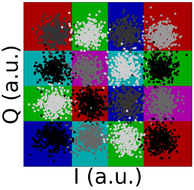
XXXVIII SIMPÓSIO BRASILEIRO DE TELECOMUNICAÇÕES E PROCESSAMENTO DE SINAIS - SBrT 2020, 22–25 DE NOVEMBRO DE 2020, FLORIANÓPOLIS, SC
supervised classification, respectively. As a lazy algorithm,
K-nearest neighbors (KNN) does not require to fit a set of
parameters to a training sequence [19], leading to an extremely
simple learning process [18]. Therefore, it is a good solution
for flexible systems where training has to be fast. Nevertheless,
to the best of our knowledge, KNN algorithm has not been yet
tested in links employing standard single mode fibers (SSMF)
where the dispersion parameter is around 16 ps/(km·nm).
In this work, we numerically implement and optimize a
KNN-based classifier to mitigate the nonlinear effects (NLPN)
caused by SPM on a 16-QAM digital coherent optical system.
The rest of the paper is organized as followed: Section II
describes the fundamentals of KNN, in Section III, we describe
the simulation setup used in this work, Section IV discusses
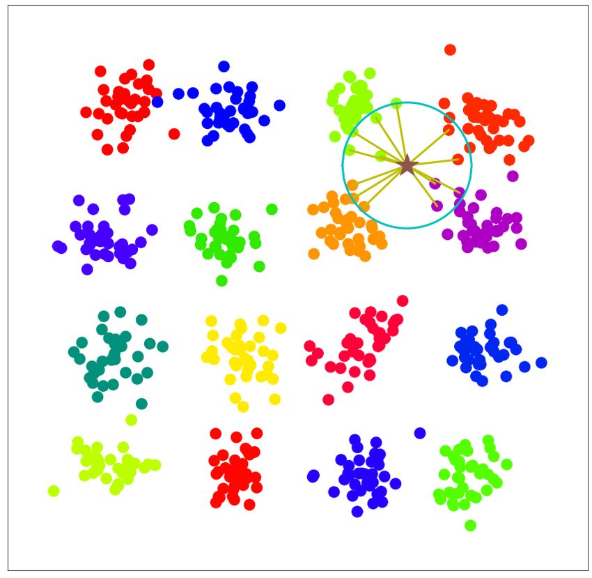
the obtained results, and Section V concludes our work. Fig. 1. KNN classification with K = 13 of a new incoming symbol identified
by a star marker. The adjacent table indicates the distance and the class of
II. K- NEAREST NEIGHBORS the k nearest symbols.
As a supervised classification algorithm, KNN requires
a training data set of size Ntr , where each received sym-
bol is represented by an N -dimensional feature vector x(i) Another point to highlight about the KNN simplicity is that
and its label, which is a natural constant y (i) indicating it depends only on a single model parameter, K, which is set
its class. Thus, in KNN, training process consists in just before the training stage. However, the size of training set is
storing the set of training symbols and their respective labels, also an important factor to be considered, as this impacts both
{x(i) , y (i) }, 1 ≤ i ≤ Ntr , for subsequent comparison. the performance and the complexity of the classification. Thus,
When a new symbol with features x(j) is received, its if the algorithm requires a low number of training symbols,
Euclidean distances di,j to all the stored training symbols x(i) Ntr , we will have a shorter overhead and higher information
are computed employing: throughput. In Section IV, we study the effect of both K and
v Ntr on the system performance to find their optimum values.
u uX N 2
(i) (j)
d = d x(i) , x(j) = t
i,j xn − xn , (1) III. S IMULATION SETUP
n=1
Fig. 2 shows the setup relying on co-simulation between
where subindex n indicates the n-th component of the feature
Matlab and VPI Transmission Maker. This setup was used
vector. After calculating the distance to all the training sym-
to evaluate the KNN classification in a LR-PON utilizing 16-
bols, the K symbols with shortest di,j are selected, hence the
QAM modulation. Due to its flexibility, Matlab was adopted to
name K nearest neighbors. The most common class among the
implement the electrical modulation, DSP, and demodulation
neighbor symbols is then assigned to x(j) . To avoid a tie in
decision, the parameter K must be odd in binary classification
but there is not such a restriction for multi-class classification DAC
problems. DP-MZM
QAM mapper
LD1 VOA SSMF1
In Fig. 1, we show an example of the KNN-based classi-
S/P
fication of a 16-QAM constellation with a training set of 35
symbols per class. Then, a total number of 560 symbols were EDFA
used for illustration purposes. The symbols are labeled from DAC SSMF2 Att.
1 to 16, which are represented in the plot from the left-to-
right and top-to-bottom. A K of 13 was chosen, meaning that
the 13 nearest symbols will be used for the classification of DSP
the example symbol that is identified with a star marker. As +
Phase noise comp.
LPF
can be seen, the example symbol is located in the vicinity ADC
90o hybrid
CD comp.
LPF -
of the symbols corresponding to the classes 3, 4, 7, and 8. LD2
KNN
P/S
S/P
The length of the lines from the example symbol represent LPF +
ADC
the distances between it and the 13 nearest symbols, while the LPF -
radius of the circle around it shows the distance to the farthest
K nearest symbol. To facilitate the interpretation of the KNN
classification method, a table including the distances to the Fig. 2. Illustration of the simulated coherent LR-PON system. S/P: serial-
K nearest neighbors and their associated classes is included. to-parallel conversion. DAC: digital to analog converter. LD:laser diode. DP-
MZM: dual parallel-Mach-Zenhder modulator. EDFA: erbium-doped fiber
As shown, most of the the K symbols with shortest distance amplifier. VOA: variable opticalattenuator. SSMF: standard single mode
belong to class 3 and, consequently the example symbol will fiber. Att: attenuator. LPF: low-pass filter. ADC: analog-to-digital converter.
be labeled as class 3. DSP:digital signal processing.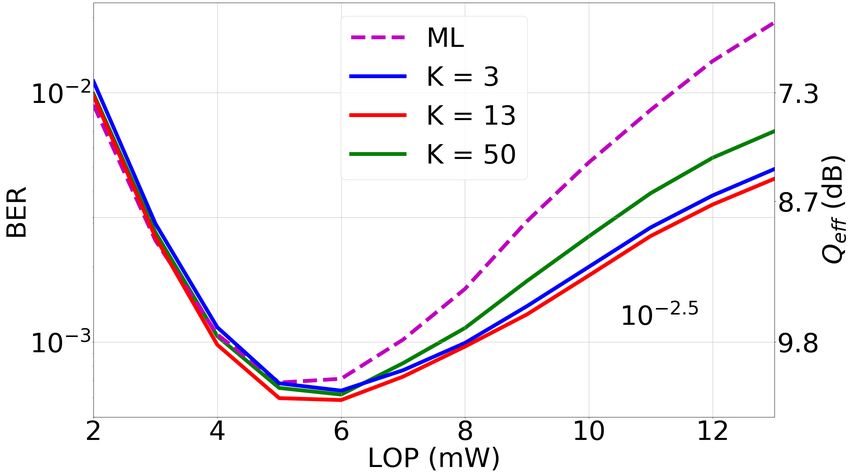
XXXVIII SIMPÓSIO BRASILEIRO DE TELECOMUNICAÇÕES E PROCESSAMENTO DE SINAIS - SBrT 2020, 22–25 DE NOVEMBRO DE 2020, FLORIANÓPOLIS, SC

stages, while VPI Transmission Maker was used to simulate                            IV. R ESULTS AND D ISCUSSION
the electrical-to-optical conversion, fiber transmission, and
signal detection.                                                  A. Performance analysis
   The system performance was assessed comparing the bit
error ratio (BER) and the effective Q factor of the proposed                   (a)
classification method with those obtained using the commonly
adopted maximum likelihood (ML). Due to the non-Gaussian
distribution of the constellation points, the BER was computed
by error counting, and the Q factor was obtained from√the
BER, by inverting the expression BER = 1/2 · erf c(Q/ 2),
where erf c represents the complementary error function [20].
   In the transmitter, the first stage consisted in a serial-to-
parallel conversion of the incoming 56-Gbps bit stream to
4-bit blocks for mapping into a 16-QAM constellation. The
in-phase and quadrature components of the mapped symbols
were oversampled to emulate the digital-to-analog conversion
and employed to drive the dual parallel Mach–Zehnder mod-                (b)                     (c)                     (d)
ulator (DP-MZM). This DP-MZM was used to modulate a
continuous wave (CW) laser with a linewidth of 100 kHz             ML

                                                                                                                                             ML
and an emission power of 1 mW operating at 1550 nm. The
power of the modulated signal was boosted by an erbium-
doped fiber amplifier (EDFA), which had an output of 13 mW.
Since the EDFA gain was not too high, no significant amount
of amplified spontaneous emission noise was added. Finally, a            (e)                     (f)                     (g)
variable optical attenuator (VOA) was used to sweep the power
                                                                   KNN

                                                                                                                                             KNN
at the input of the distribution network from 2 to 13 mW.
   The distribution network was formed by an 80-km-length
standard single mode fiber (SSMF) link, an 18-dB attenuator
representing the splitting loss of the signal to 64 users, and a
second link of SSMF with a length of 20 km.                        Fig. 3. Performance analysis. (a) BER obtained using ML and KNN in
   At the receiver front-end, the incoming signal was first        terms of the launch optical power. For KNN three different configurations are
                                                                   considered: K = 3, 13, and 50. (b-d) Received constellations alongside with
mixed with a 1-mW CW local oscillator laser employing a            the obtained decision regions for ML at 2, 6, and 13 mW. (e-f) The same as
90o optical hybrid network. The corresponding in-phase and         (b-d) but for KNN classification.
quadrature components of the received signal were converted
to the electrical domain by utilizing two pairs of balanced           Fig. 3(a) shows the BER obtained when the received sym-
photodetectors, whose bandwidth response was modeled by a          bols are classified utilizing ML and KNN methods. To ensure
4th-order electrical Bessel filters.                               optimum performance of KNN, we swept the value of K,
   At the DSP, the first module carried out the compensation       i.e. the number of neighbors to be considered, obtaining an
of the CD in the frequency-domain. The time synchronization        optimum of K = 13. Nevertheless, in Fig. 3(a) we present
stage relied on a pilot sequence of 64 symbols of alternating      the results for K = 3, 13, and 50 to show the performance
amplitudes, optimizing the sampling times by the method of         of choosing a small, an optimum, and a large value of K.
cross-correlation maximization. A downsampling process was         As can be observed, at low power levels, where the dominant
then performed to get a single sample per symbol. Through          impairment is the additive noise, the BER obtained employing
a blind search algorithm, the stochastic phase rotation caused     both methods is similar, regardless of the configuration of
by the combined phase noises of both transmitter and receiver      KNN. As we increase the launch optical power (LOP), KNN
laser diodes was compensated. It is worth mentioning that,         progressively outperforms ML. This point can be seen at
as the total length of the link was 100 km, the accumulated        intermediate LOPs where NLPN begins to be appreciable but
PMD is significantly smaller than the symbol period and,           is specially notorious at higher values of LOP. As a result of
consequently, it did not require compensation. After overhead      the partial nonlinearity mitigation, it is possible to reduce the
removal, 81,500 data symbols were available. These symbols         optimal BER from 7.12·10−4 obtained using ML to 6.37·10−4 ,
were divided in a training set of up to 10,000 symbols             5.85·10−4 , and 6.15·10−4 when adopting KNN with K = 3, 13,
and a fixed test set of 71,500 symbols. The signal quality         and 50, respectively. This system performance improvement
was assessed considering the bit error ratio (BER) calculated      corresponds to a 0.15-dB increase in the effective Q-factor.
by error counting, whereas as mentioned the performance            In addition, for a forward error correction (FEC) threshold of
improvement of the KNN classification method was quantified        2 · 10−3 , by employing KNN, the transmission power limit
comparing the BER at optimum launch optical power for KNN          can be increased from 8 mW to 10 mW, which represents a
and the that of ML.                                                ≈ 1 dB gain in the power margin.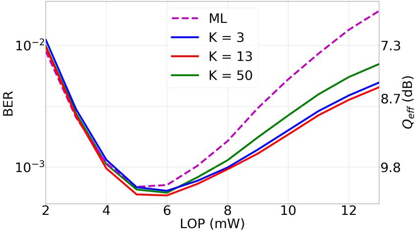
XXXVIII SIMPÓSIO BRASILEIRO DE TELECOMUNICAÇÕES E PROCESSAMENTO DE SINAIS - SBrT 2020, 22–25 DE NOVEMBRO DE 2020, FLORIANÓPOLIS, SC
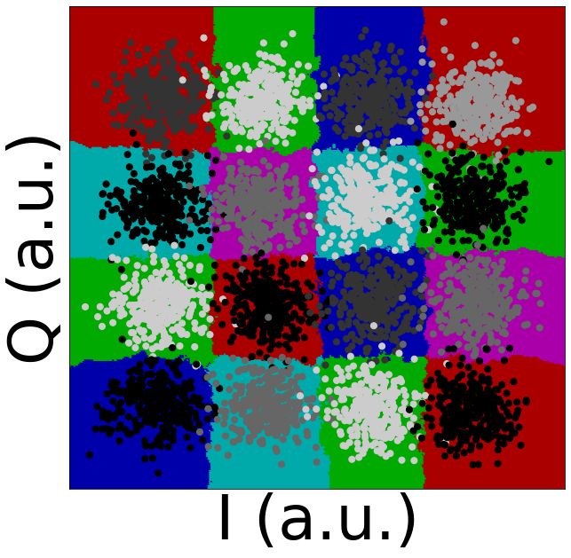
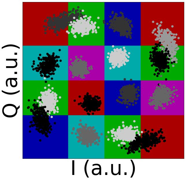
In order to see why KNN-based classification presents a
better performance than ML, in Fig. 3(b-d) we illustrate the
constellations alongside with the decision regions using ML
at LOPs of 2, 6, and 13 mW, respectively. As can be seen,
when using ML, the boundaries of the decision regions are
straight and orthogonal, which are suitable for low power
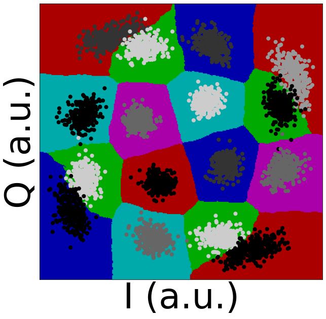
levels but are not optimum for high LOPs. Fig. 3(e-g), on the
other hand, represent the same constellations but employing a
KNN classifier instead of ML. At low level powers, KNN and
ML traced similar boundaries and, consequently, they lead to
almost the same BER values. This can be understood by noting
that when the additive noise is dominant, the randomness of
the generated pattern avoids the class of new symbols to be
predicted based on previously received symbols. At higher Fig. 5. Calculated BER in terms of the training set size for different values
of K, i.e. K=3, 13, and 50. The optimum BER achieved using ML is also
values of LOP, the resulted boundaries are not straight any- included as a benchmark.
more. These curved boundaries better fit the dispersion of the
points, thus reducing the amount of errors. Such improvement
is possible because, even if complicated, the underlying NLPN B. Training test size analysis
effect is deterministic and, therefore, a pattern can be found
by means of machine learning algorithm. The optical channel in a LR-PON system is relatively
static, which means that the training stage is not accomplished
As mentioned in Section I, in multi-level modulation for-
frequently. Nevertheless, it is still important to analyze the
mats, NLPN affects more strongly symbols with higher in-
optimal training set size, to assess the capability of the system
tensity. This can be clearly observed in Fig. 3(d) and (g).
to adapt to eventual re-configurations. In Fig. 5, we show the
For the sake of visualization of amplitude-dependent nonlinear
BER convergence curves as a function of the training set size
impairments mitigation, it is useful to analyze the BER of
for three KNN configurations: K = 3, 13 and 50. In all cases
each class individually rather than its average. Considering
a LOP of 6 mW was considered. Maintaining the test set fixed,
this, Fig. 4 represents the BER of each class separately for
the training was performed in subsets of sizes ranging from 10
both ML (a-c) and KNN detection (d-f) at LOPs of 2, 6, and
to 2,000 symbols. Taken into account that different training set
13 mW. The BER values presented in Fig. 4 can be interpreted
examples give different performance results, for each training
as the complimentary of the classification accuracy of the
size we performed the training 50 times by selecting random
confusion matrix. Looking at the highest LOP, Fig. 4(c) and
subsets. As expected, for low training set sizes, the BER is
(f), it is possible to see that the KNN allows to reduce the
high for all the contemplated configurations. As the training
BER of the symbols with highest amplitude from 5·10−3 to
set size is increased, the BER tends to converge. It can be
1.5·10−3 , which most contributes to the total BER is given by
observed that for a small value of K, the algorithms requires
the classification of the four vertexes symbols. Nevertheless,
a shorter training size to converge. For a higher value of K,
even if KNN mitigates the effect of NLPN, the vertex symbols
as K = 50, the convergence is slower but it converges to
of the constellation still present higher BER.
a smaller BER value. Thus, K = 13 presents an optimum
tradeoff between convergence and perfomance. For the sake of
comparison, the dashed line in Fig. 5 shows the BER achieved
when the ML method is used. Hence, we can conclude that
(a) (b) (c)
for the system under test, a good performance KNN can
be achieved with a small Ntr and, consequently, with low
computational complexity.
V. C ONCLUSIONS
(d) (e) (f)
In this paper we analyzed the capability of KNN for
mitigating the effect of the nonlinear phase noise in coherent
LR-PONs employing 16-QAM. Simulation results reveal that
for a 100-km link with a 1×64 splitting ratio and operating at
56 Gbps, the optimum configuration is achieved for a value of
K =13, which results in a Q-factor improvement of 0.15 dB
Fig. 4. BER for each class for (a-c) ML detection and (d-f) KNN-based
classification with optimum K. Both methods are tested at LOPs of 2, 6, and
when compared to ML. The effect of the training set size was
13 mW. also investigated, showing that higher values of K require
larger training sets. In particular, for K=13, KNN requires
approximately 500 symbols to get optimum performance.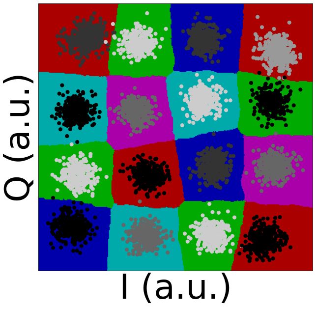
XXXVIII SIMPÓSIO BRASILEIRO DE TELECOMUNICAÇÕES E PROCESSAMENTO DE SINAIS - SBrT 2020, 22–25 DE NOVEMBRO DE 2020, FLORIANÓPOLIS, SC

                         ACKNOWLEDGMENTS                                           [11] J. Pan and C. Cheng, “Wiener–Hammerstein model based electrical
                                                                                        equalizer for optical communication systems,” Journal of Lightwave
    The authors thank the National Council for Scien-                                   Technology, vol. 29, no. 16, pp. 2454–2459, 2011.
tific and Technological Development (CNPq, grant numbers                           [12] J. Torres-Zugaide, I. Aldaya, G. Campuzano, E. Giacoumidis, J. Beas,
432303/2018-9 and 311035/2018-3) and the São Paulo Re-                                  and G. Castañón, “Range extension in coherent OFDM passive optical
search Foundation (FAPESP, grant 2018/25339-4).                                         networks using an inverse hammerstein nonlinear equalizer,” Journal of
                                                                                        Optical Communications and Networking, vol. 9, no. 7, pp. 577–584,
                                                                                        2017.
                               R EFERENCES                                         [13] S. Shalev-Shwartz and S. Ben-David, Understanding Machine Learning:
                                                                                        From Theory to Algorithms. USA: Cambridge University Press, 2014.
 [1] G. P. Agrawal, “Optical communication: its history and recent progress,”
     in Optics in Our Time. Springer, Cham, 2016, pp. 177–199.                     [14] I. Aldaya, E. Giacoumidis, G. de Oliveira, J. Wei, J. L. Pita, J. D.
 [2] C. V. N. Index, “Forecast and methodology 2017–2022,” Cisco: San                   Marconi, E. A. M. Fagotto, L. Barry, and M. L. F. Abbade, “Histogram
     Jose, CA, USA, 2019.                                                               based clustering for nonlinear compensation in long reach coherent
 [3] P. J. Winzer, “High-spectral-efficiency optical modulation formats,”               passive optical networks,” Applied Sciences, vol. 10, no. 1, p. 152, 2020.
     Journal of Lightwave Technology, vol. 30, no. 24, pp. 3824–3835, 2012.        [15] D. Zibar, O. Winther, N. Franceschi, R. Borkowski, A. Caballero,
 [4] D. Lavery, R. Maher, D. S. Millar, B. C. Thomsen, P. Bayvel, and                   V. Arlunno, M. N. Schmidt, N. G. Gonzales, B. Mao, and Y. Ye,
     S. J. Savory, “Digital coherent receivers for long-reach optical access            “Nonlinear impairment compensation using expectation maximization
     networks,” Journal of Lightwave Technology, vol. 31, no. 4, pp. 609–               for dispersion managed and unmanaged PDM 16-QAM transmission,”
     620, 2012.                                                                         Optics Express, vol. 20, no. 26, pp. B181–B196, 2012.
 [5] D. Lavery, B. C. Thomsen, P. Bayvel, and S. J. Savory, “Reduced com-          [16] Y. Fukumoto, S. Owaki, T. Sakamoto, N. Yamamoto, and M. Nakamura,
     plexity equalization for coherent long-reach passive optical networks,”            “Experimental demonstration of SPM compensation based on digital
     Journal of Optical Communications and Networking, vol. 7, no. 1, pp.               signal processing using a complex-valued neural network for 40-Gbit/s
     A16–A27, 2015.                                                                     optical 16QAM signals,” in 23rd Opto-Electronics and Communications
 [6] M. N. Chughtai, “Nonlinear phase noise in fiber optical communication,”            Conference (OECC), July 2018, pp. 1–2.
     Ph.D. dissertation, Chalmers University of Technology, 2009.                  [17] D. Wang, M. Zhang, Z. Li, Y. Cui, J. Liu, Y. Yang, and H. Wang,
 [7] C. McKinstrie, S. Radic, and C. Xie, “Reduction of soliton phase jitter            “Nonlinear decision boundary created by a machine learning-based
     by in-line phase conjugation,” Optics Letters, vol. 28, no. 17, pp. 1519–          classifier to mitigate nonlinear phase noise,” in European Conference
     1521, 2003.                                                                        on Optical Communication (ECOC). IEEE, 2015, pp. 1–3.
 [8] K.-P. Ho, “Mid-span compensation of nonlinear phase noise,” Optics
                                                                                   [18] D. Wang, M. Zhang, M. Fu, Z. Cai, Z. Li, H. Han, Y. Cui, and B. Luo,
     Communications, vol. 245, no. 1-6, pp. 391–398, 2005.
                                                                                        “Nonlinearity mitigation using a machine learning detector based on k-
 [9] C.-Y. Lin, R. Asif, M. Holtmannspoetter, and B. Schmauss, “Nonlinear
                                                                                        nearest neighbors,” IEEE Photonics Technology Letters, vol. 28, no. 19,
     mitigation using carrier phase estimation and digital backward propaga-
                                                                                        pp. 2102–2105, 2016.
     tion in coherent QAM transmission,” Optics Express, vol. 20, no. 26,
     pp. B405–B412, 2012.                                                          [19] E. Alpaydin, Introduction of Machine Learning. The MIT Press, 2014.
[10] L. Liu, L. Li, Y. Huang, K. Cui, Q. Xiong, F. N. Hauske, C. Xie,              [20] R. A. Shafik, M. S. Rahman, and A. R. Islam, “On the extended
     and Y. Cai, “Intrachannel nonlinearity compensation by inverse Volterra            relationships among EVM, BER and SNR as performance metrics,”
     series transfer function,” Journal of Lightwave Technology, vol. 30, no. 3,        in International Conference on Electrical and Computer Engineering.
     pp. 310–316, 2012.                                                                 IEEE, 2006, pp. 408–411.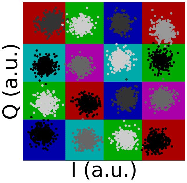
You can also read