MO2TIALC2: A NEW ORDERED LAYERED TERNARY CARBIDE
←
→
Page content transcription
If your browser does not render page correctly, please read the page content below
Mo2TiAlC2: A new ordered layered ternary
                  carbide

   Babak Anasori, Joseph Halim, Jun Lu, Cooper A. Voigt, Lars Hultman and Michel W.
                                       Barsoum

                          Linköping University Post Print

                    N.B.: When citing this work, cite the original article.

Original Publication:
Babak Anasori, Joseph Halim, Jun Lu, Cooper A. Voigt, Lars Hultman and Michel W.
Barsoum, Mo2TiAlC2: A new ordered layered ternary carbide, 2015, Scripta Materialia, (101),
5-7.
http://dx.doi.org/10.1016/j.scriptamat.2014.12.024
Copyright: Elsevier
            http://www.elsevier.com/

Postprint available at: Linköping University Electronic Press
            http://urn.kb.se/resolve?urn=urn:nbn:se:liu:diva-117200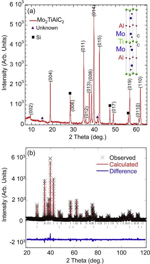
Mo2TiAlC2: A New Ordered Layered Ternary
                     Carbide
Babak Anasori1*, Joseph Halim1,2, Jun Lu2, Cooper A. Voigt1, Lars Hultman2 and Michel
                                     W. Barsoum1
 1
     Department of Materials Science & Engineering, Drexel University, Philadelphia, PA
                                         19104,USA
     2
       Thin Film Physics Division, Department of Physics, Chemistry and Biology (IFM),
                    Linköping University, SE-581 83 Linköping, Sweden

* Corresponding author. Tel.: +1 267 217 2185. E-mail: anasori@drexel.edu

Abstract

         Herein we report on the synthesis of a new layered ternary carbide, viz.

Mo2TiAlC2, that was synthesized by heating an elemental mixture at 1600 ºC for 4 h

under Ar flow. Its lattice parameters were calculated via Rietveld analysis of powder X-

ray diffraction patterns to be 2.997 Å and 18.661 Å. High-resolution scanning

transmission electron microscopy further showed that this phase is ordered, with the Ti

layers sandwiched between two Mo layers in a M3AX2 type layered ternary carbide

structure.

Keywords: Ordered MAX phases, Ternary carbides

                                                                                           1
The MAX phases are a large family of hexagonal, ternary, carbides and nitrides
with a general formula Mn+1AXn, (MAX) where n = 1, 2, 3 etc., M is an early transition
metal (Sc, Ti, Zr, Hf, V, Nb, Ta, Cr, Mo and etc.), A is a group 13 to 16 element (Al, Ga,
In, Tl, Si, Ge, Sn, Pb, P, As etc.) and X is carbon and/or nitrogen [1-3]. These phases
combine some of the best attributes of metals and ceramics, which can be attributed to
their thermodynamically nanolaminated layered structure and the metal-like nature of
their bonding. Like metals, they are electrically and thermally conductive, most readily
machinable [4, 5], not susceptible to thermal shock, plastic at high temperatures, and
exceptionally damage tolerant [6]. Like ceramics, some of them are elastically rigid
(Young’s moduli > 300 GPa), lightweight (≈ 4 Mg/m3), maintain their strengths to high
temperatures [1, 3] and some of them are creep and oxidation resistant [7-10].
Among the more than 70+ different MAX phases that have been synthesized to
date, some of the Al-containing ones, notably Ti2AlC, have attracted the most attention
due to their exceptional oxidation resistance as a result of thin protective alumina layer
that forms on its surface [7, 10, 11]. More recently, crack self-healing characteristics have
also been reported during oxidation of Ti2AlC and Ti3AlC2 [12, 13].
Based on all the studies carried out over the past 60 years, only certain M
elements can be combined with certain A elements to form MAX phases. For instance, Al
containing MAX phases can only have Ti, V, Cr, Nb and Ta as their M elements.
Conversely, Mo, Hf, Zr, and others do not form Al-containing MAX phases.
Furthermore, almost all solid solution MAX phases synthesized to date follow similar
rules. There are few exceptions wherein a solid solution contains a M element, that does
not generally bond to Al, such as Zr in (Nb0.8,Zr0.2)2AlC [14], and (Nb0.6,Zr0.4)2AlC [15],
2and Mn in (Cr0.7,Mn0.3)2GaC [16]. In both examples the mass fraction of the non-Al
bonding M element is less that 0.5 of the total M-content.
Recently, Liu et al. reported on synthesizing of Cr2TiAlC2, from Cr2AlC and TiC
[17]. Based on their neutron diffraction data, they concluded that the Cr-layers
sandwiched the Ti-layers in a M3AX2 MAX phase structure. Even more recently, Caspi et
al. used high-resolution neutron diffraction to show that when n = 2, in
the (Cr0.5V0.5)n+1AlCn system, the V and Cr atoms showed a strong tendency to
ordering, with V only occupying the middle layer. Said otherwise, the 2a (000) sites were
fully occupied by vanadium [18].
Of special interest to this work are Mo-containing MAX phases. To date the only
known Mo-containing MAX phase was Mo2GaC [19]. In this study, for the first time, we
report on a new Mo-containing ordered MAX phase, Mo2TiAlC2. In this phase, which is
isostructural with Ti3SiC2 [4, 20], the Ti atoms are sandwiched between two Mo-layers
that in turn are adjacent to the Al planes resulting in a Mo-Ti-Mo-Al-Mo-Ti-Mo stacking
order. The C-atoms are in between the Mo and Ti layers.
To synthesize this compounds elemental powders of Mo, Ti, Al and graphite (all
from Alfa Aesar, Ward Hill, MA), with mesh sizes of -250, -325, -325 and -300,
respectively, were mixed in the molar ratio of Mo:Ti:Al:C 2:1:1.1:2 with zirconia milling
balls, in plastic jars, for 18 h. The powder mixture was then placed in a covered alumina
crucible and heated at a rate of 5 ºC/min to 1600 ºC and held for 4 h under flowing argon
(Ar). After furnace cooling, the slightly sintered porous compact was milled into a fine
powder using a TiN-coated milling bit.
3X-ray diffraction (XRD) was carried out on a diffractometer (Rikagu Smartlab,
Tokyo, Japan), using step scans of 0.02º in the 3°–120° 2 theta range with a step time of 7
s with a 10 x 10 mm2 window slit. Scans were made with Cu-Kα radiation (40 KV and 44
mA). Ten wt.% silicon powder was added to the sample powder for XRD as an internal
standard to calibrate the diffraction angles and instrumental peak broadening.
The XRD diffractograms were analyzed by the Rietveld refinement method, using
the FULLPROF code [21, 22]. Refined parameters were: five background parameters,
scale factors from which relative phase fractions are evaluated, X and Y profile
parameters for peak width, lattice parameters (LPs) and atomic positions for all phases.
High resolution scanning electron microscopy (HRSTEM) and X-ray energy dispersive
spectroscopy (EDX) were carried out with the a double corrected FEI Titan3 60–300
operated at 300 kV, equipped with the Super-X EDX system. Selected area electron
diffraction (SAED) characterization was performed using a FEI Tecnai G2 TF20 UT
instrument equipped with a field emission gun runs at a voltage of 200 kV and a point
resolution of 0.19 nm.
The specimens were prepared by embedding the MAX powder in a Ti grid,
reducing the Ti-grid thickness down to 50 μm via mechanical polishing and finally Ar+
ion milling to reach electron transparency.
Figure 1a shows the XRD pattern obtained from the powder. Each peak is labeled
on the pattern. Figure 1b compares the experimental XRD pattern (black) with the
calculated pattern obtained from the Rietveld analysis (red) from 2 = 21 to 120º. The
difference between the two is shown in (blue). The χ2 value was 2.44, which shows the
good agreement between model and measured data. The sample was found to be a
4predominately pure Mo2TiAlC2 phase. Mo2TiAlC2 a-LP and c-LP were calculated from
the refinement to be 2.99703(4) and 18.6608(3) Å, respectively.
Small peaks of a M2AX phase were also identified as the only impurity in the
powder. A solid solution (MoTi)2AlC showed a very good fit with it. The (MoTi)2AlC a-
and c-LPs were calculated from the refinement to be 3.021(5) and 11.756(4) Å,
respectively. The reported uncertainties of all structural values determined from Rietveld
refinement are the uncertainties of the refinement process and are mainly of statistical
origin. From the refined LPs of the internal Si standard, we evaluate the systematic
uncertainty to be < 0.01 %. In Mo2TiAlC2, the refinement calculated z-coordinate for Mo
at the x, y coordinates of (2/3, 1/3) was 0.13327(6) and for C at x, y coordinates of (1/3,
2/3) was 0.0691(5). In (MoTi)2AlC the z-coordinate for M (Mo and Ti) at the x, y
coordinates of (1/3, 2/3) was 0.069(2).
Given the 2:1 ratio of Mo:Ti and based on the recent work showing ordering of
the M-atoms in Cr2TiAlC2 [17], it was reasonable to assume that this phase was ordered
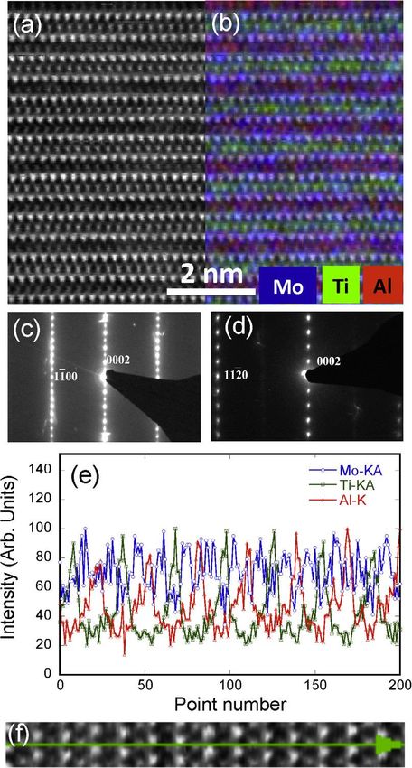
as well. A schematic of such a unit cell is shown as an inset in Fig. 1. HRTEM images of
a sample along the [11 2 0] zone axis with its SAED are shown in Figs. 2a and c,
respectively. Figure 2d shows the SAED along the [1 1 00] zone axis. The a- and c-LP
were measured from SAED images to be 2.93(3) and 18.9(7) Å, both values in good
agreement with those measured from the XRD patterns.
Figure 2b is the overlap of Fig. 2a and the total EDX mapping, in which the Mo,
Ti and Al atoms are shown in blue, green and red, respectively. Based on this map it is
clear that every green, or Ti, layer is sandwiched between two blue, or Mo, layers. Figure
2e shows an EDX line scan along the [11 2 0] axis of the micrograph shown in Fig. 2f.
5The Mo, Ti and Al lines have the same coloring as in Fig. 2b. In other words, the line
scan confirms the ordering sequence.
Based on the totality of our results it is thus reasonable to conclude that
Mo2TiAlC, is highly ordered, with the Mo layers sandwiching the Ti- layers in a structure
that is iso-structural with Ti3SiC2 [20]. In this compound the layer sequence – excluding
C – is: Al-Mo-Ti-Mo-Al-Mo-Ti-Mo etc.
It is worth noting that (MoTi)2AlC was the only other phase detected in the XRD
patterns. This M2AX phase is thus also a new solid solution in the MAX phase family
that to date has not been reported. However, given its chemistry, it is unlikely that this
MAX phase is ordered. This comment notwithstanding, more work should be dedicated
to synthesizing and characterizing this new phase.
The importance of this work lies beyond the compounds made herein, since it
opens up a new avenue to make MAX phases with bonds that had not been previously
observed. For example, in this work the MAX phase created contains Mo-Al bonds. As
noted in the introduction, before this work the only Mo-containing MAX phase was
comprised of Mo-Ga-Mo layers. We note in passing that Mo3AlC2 does not exist and it
follows that the Ti layer is crucial in stabilizing it and lowering its energy.
The fact that Mo is on the outer layers of M sites might lead to different properties
for this new phase than a regular Ti-Al containing solid solution. The implications for
totally new MXenes chemistries has also not escaped us and will be the subject of a
separate forthcoming paper.
6Acknowledgement
This work was partially supported by the Army Research Office (W911NF-11-1-
0525). J.H. and MW.B. acknowledges the support from the SSF synergy grant
FUNCASE Functional Carbides and Advanced Surface Engineering. The Linköping
Electron Microscopy Laboratory was supported by the Kunt and Alice Wallenberg
Foundation.
7References
[1] M.W. Barsoum, M. Radovic, Annual Review of Materials Research, 41 (2011) 195-
227.
[2] P. Eklund, M. Beckers, U. Jansson, H. Högberg, L. Hultman, Thin Solid Films, 518
(2010) 1851-1878.
[3] M.W. Barsoum, MAX Phases: Properties of Machinable Ternary Carbides and Nitrides,
John Wiley & Sons, 2013.
[4] M.W. Barsoum, T. ElRaghy, J Am Ceram Soc, 79 (1996) 1953-1956.
[5] M.W. Barsoum, D. Brodkin, T. ElRaghy, Scripta Materialia, 36 (1997) 535-541.
[6] M.W. Barsoum, M.C. Flemings, E.J. Kramer, S. Mahajan, P. Veyssiere, In:
Encyclopedia of materials science and technology, (2006).
[7] D.J. Tallman, B. Anasori, M.W. Barsoum, Materials Research Letters, 1 (2013) 115-
125.
[8] B. Anasori, E.a.N. Caspi, Y. Elraheb, M.W. Barsoum, Journal of Alloys and
Compounds, 580 (2013) 550-557.
[9] D.J. Tallman, M. Naguib, B. Anasori, M.W. Barsoum, Scripta Materialia, 66 (2012)
805-808.
[10] M. Sundberg, G. Malmqvist, A. Magnusson, T. El-Raghy, Ceramics International, 30
(2004) 1899-1904.
[11] X.H. Wang, Y.C. Zhou, Oxidation of Metals, 59 (2003) 303-320.
[12] G.M. Song, Y.T. Pei, W.G. Sloof, S.B. Li, J.T.M. De Hosson, S. van der Zwaag,
Scripta Materialia, 58 (2008) 13-16.
[13] H. Yang, Y. Pei, J. Rao, J.T.M. De Hosson, Journal of Materials Chemistry, 22 (2012)
8304-8313.
[14] M. Naguib, G. Bentzel, J. Shah, J. Halim, E. Caspi, J. Lu, L. Hultman, M. Barsoum,
Materials Research Letters, (2014) 1-8.
[15] H. Nowotny, P. Rogl, J.C. Schuster, Journal of Solid State Chemistry, 44 (1982) 126-
133.
[16] A. Mockute, J. Lu, E.J. Moon, M. Yan, B. Anasori, S.J. May, M.W. Barsoum, J.
Rosen, Materials Research Letters, (2014) 1-7.
[17] Z. Liu, E. Wu, J. Wang, Y. Qian, H. Xiang, X. Li, Q. Jin, G. Sun, X. Chen, J. Wang,
M. Li, Acta Mater, 73 (2014) 186-193.
[18] E.N. Caspi, P. Chartier, F. Porcher, F. Damay, T. Cabioc'h, Materials Reseach Letters,
(2014) 1-7.
[19] L.E. Toth, Journal of the Less Common Metals, 13 (1967) 129-131.
[20] W. Jeitschko, H. Nowotny, Monatshefte für Chemie, 98 (1967) 329-337.
[21] H.M. Rietveld, Journal of Applied Crystallography, 2 (1969) 65-71.
[22] J. Rodríguez-Carvajal, Physica B: Condensed Matter, 192 (1993) 55-69.
8Figure Captions
Figure 1. (a) Powder XRD patterns of Mo2TiAlC2, black rectangles show location
of Si powder peaks, added as an internal standard; Inset shows schematic of Mo2TiAlC2
unit cell. (b) Powder XRD patterns of Mo2TiAlC2, observed pattern (black crosses),
Rietveld generated pattern (red line) and difference between the two (blue line). The
black and blue ticks below the pattern represent the peak positions of the Mo2TiAlC2
phase, and Si phase, respectively.
Figure 2. (a) HRSTEM of Mo2TiAlC2 along the [11 2 0] zone axis, (b) the overlap of
EDX mapping on (a) showing the Mo atoms in blue, Ti atoms in green and Al atoms in
red, (c) and (d) SEAD of Mo2TiAlC2 along the [11 2 0] and [11̅00] zone axes,
respectively, (e) EDX line scan profile of Mo (blue circles), Ti (green squares), and Al
(red triangles), (f) STEM of the EDX line scanned region the results of which are shown
in (e).
9Fig. 1
10Fig. 2
11You can also read