Modeling and Analysis of Eavesdropping Attack in 802.11ad mmWave Wireless Networks
←
→
Page content transcription
If your browser does not render page correctly, please read the page content below
INL/JOU-18-45648-Revision-0

Modeling and Analysis of
Eavesdropping Attack in
802.11ad mmWave
Wireless Networks

Arup Bhuyan, Zhi Sun, Sarankumar
Balakrishnan, Pu Wang

May 2019

The INL is a U.S. Department of Energy National Laboratory
operated by Battelle Energy Alliance
INL/JOU-18-45648-Revision-0

Modeling and Analysis of Eavesdropping Attack in
     802.11ad mmWave Wireless Networks

    Arup Bhuyan, Zhi Sun, Sarankumar Balakrishnan, Pu Wang

                           May 2019

                 Idaho National Laboratory
                  Idaho Falls, Idaho 83415

                      http://www.inl.gov

                        Prepared for the
                   U.S. Department of Energy
                    Office of Nuclear Energy
                Under DOE Idaho Operations Office
                  Contract DE-AC07-05ID14517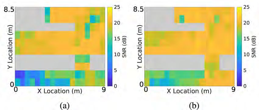
Received April 4, 2019, accepted May 6, 2019, date of publication May 28, 2019, date of current version June 11, 2019.
Digital Object Identifier 10.1109/ACCESS.2019.2919674

Modeling and Analysis of Eavesdropping Attack
in 802.11ad mmWave Wireless Networks
SARANKUMAR BALAKRISHNAN 1 , (Student Member, IEEE), PU WANG 2 , (Member, IEEE),
ARUPJYOTI BHUYAN3 , (Senior Member, IEEE), AND ZHI SUN 1 , (Member, IEEE)
1 Department   of Electrical Engineering, University at Buffalo, The State University of New York, Buffalo, NY 14260, USA
2 Department   of Computer Science, University of North Carolina at Charlotte, Charlotte, NC 28223, USA
3 Idaho   National Laboratory, Idaho Falls, ID 83402, USA
Corresponding author: Sarankumar Balakrishnan (sarankum@buffalo.edu)
This work was supported by the INL Laboratory Directed Research and Development (LDRD) Program under DOE Idaho Operations
Office under Grant DE-AC07-05ID14517.

  ABSTRACT         Next generation wireless communication networks utilizing 60 GHz millimeter
  wave (mmWave) frequency bands are expected to achieve multi-gigabit throughput with the use of
  highly directional phased-array antennas. These directional signal beams provide enhanced security to the
  legitimate networks due to the increased difficulties of eavesdropping. However, there still exists significant
  possibility of eavesdropping since 1) the reflections of the signal beam from ambient reflectors enables
  opportunistic stationary eavesdropping attacks, and; 2) carefully designed beam exploration strategy
  enables active nomadic eavesdropping attack. This paper discusses eavesdropper attack strategies for
  802.11ad mmWave systems and provides the first analytical model to characterize the success possibility
  of eavesdropping in both opportunistic stationary attacks and active nomadic attacks. We derive the success
  probability of eavesdropping considering the ambient reflectors in the environment and errors introduced
  in the beam exploration strategies of the proposed eavesdropping attacker models. We study the success
  probability for both opportunistic stationary attack scenario and active nomadic attack scenario through
  numerical simulations. In addition to numerical simulations, we also evaluate the proposed attacker models
  using an 802.11ad test bed consisting of commercially available off-the-shelf devices.

  INDEX TERMS Millimeter wave communications, 802.11ad, stochastic geometry, success probability,
  eavesdropping attack.

I. INTRODUCTION                                                                                   of around 7 Gbps are envisioned with the use of beamforming
Millimeter wave (mmWave) communication is considered to                                           with phased-array antennas to steer around the obstacles.
be one of the key enabling technologies of next generation                                           With the expected proliferation of 802.11ad based
very high throughput wireless networks. MmWave frequency                                          mmWave WLAN for high throughput indoor connectivity,
bands have different propagation characteristics than those                                       security of these wireless networks becomes a critical issue.
at lower microwave frequencies. At mmWave frequencies,                                            Contrary to the omni-directional signal transmission in legacy
the signal experiences high attenuation due to propagation                                        802.11 based wireless networks operating at 2.4 and 5 GHz
and penetration losses [1]. When compared to microwave                                            microwave band, 60 GHz 802.11ad mmWave networks are
frequencies at sub 6 GHz band, 60 GHz mmWave frequency                                            characterized by highly directional transmission enabled by
bands experience additional 20 dB signal attenuation. The                                         beamforming [1]. 802.11ad standard specifies a minimum
IEEE 802.11ad standard [2] addresses these challenges by                                          beamwidth of 3 degrees. Conventionally it is believed that the
using high gain directional antennas to overcome the signal                                       very narrow beamwidth offers inherent PHY security against
attenuation at 60 GHz. IEEE 802.11ad leverages the wide                                           eavesdroppers. However, such optimistic conclusion is based
bandwidth available at 60 GHz frequency band and data-rates                                       on the assumption that eavesdroppers only rely on the line of
                                                                                                  sight (LOS) link to the legitimate devices and do not have
                                                                                                  any information of the direction of the beam used by the
   The associate editor coordinating the review of this manuscript and
approving it for publication was Waleed Ejaz.                                                     legitimate devices.

                                             2169-3536 2019 IEEE. Translations and content mining are permitted for academic research only.
VOLUME 7, 2019                                     Personal use is also permitted, but republication/redistribution requires IEEE permission.             70355
                                            See http://www.ieee.org/publications_standards/publications/rights/index.html for more information.
S. Balakrishnan et al.: Modeling and Analysis of Eavesdropping Attack in 802.11ad mmWave Wireless Networks In practice, there still exists significant possibility of eaves- we analyze the success possibility of two types of eavesdrop- dropping in 802.11ad mmWave systems. On the one hand, ping attacks, including the opportunistic stationary attack many millimeter wave indoor experimental measurements and the active nomadic attack. In the opportunistic station- have shown that first order reflections from structures in an ary attack, the eavesdropper can only stay in the random indoor environment contributes to majority of signal power position of the indoor environment. We consider when the in non-line-of-sight (NLOS) [3]. Thus, in 60 GHz mmWave LOS path is available and when only NLOS path is avail- communication, along with LOS, first order reflections from able due to reflectors. Stochastic geometry based success ambient reflectors play a crucial role in the signal coverage probability analysis is developed for the eavesdropper in the of such systems. As a result, even when not in the LOS presence of LOS and reflected signal paths. In the active region of the narrow mmWave beam, it is still possible for nomadic attack, the eavesdropper can move to any location the eavesdropper to overhear the transmission due to the in the environment to launch the attack. We first develop multiple reflection paths. On the other hand, to establish the the LOS region estimation method based on the 802.11ad highly directional mmWave link, the legitimate transmitter beam search procedure so that the eavesdropper knows and receiver need to scan all the possible direction sectors to where to move. Then the successful possibility of the active search the optimal beam between themselves [2]. Due to this nomadic attack is derived. Finally, we evaluate our analytical beam searching procedure [4], eavesdropper can estimate the model under various scenarios. We also perform eavesdrop- LOS region of the beam selected by the legitimate users. Once ping experiments using commercially available 802.11ad the eavesdropper moves to the LOS region, the possibility of devices [15] and a 60 GHz mmWave transceiver from successful eavesdropping will dramatically increase. VubiQ [16]. To date, the understanding of the eavesdropping attack The main contributions of this work are summarized as in 802.11ad mmWave WLAN system is still limited to exper- below: imental results. In [5], a multi-antenna eavesdropping attack • We introduce two types of eavesdropping attack strate- strategy is proposed. The ability of the eavesdropper to reli- gies: opportunistic stationary attack and active nomadic ably detect the intentional jamming from the legitimate trans- attack. mitter is experimentally demonstrated. In [6], an attack on • We develop a tractable analytical model for success the antenna subset modulation (ASM) technique is developed probability of eavesdropping under opportunistic sta- based on compressive sensing technique. In [7], the impact of tionary attack model considering both the LOS and the reflections on the physical layer security of mmWave systems reflections from the environment. We also consider the are experimentally demonstrated. It shows that the eaves- errors introduced by beam searching procedures in our dropper can successfully eavesdrop even highly directional analytical model. signal beams when small-scale reflectors are placed along the • Next, we for the first time develop the active nomadic direction of the main beam. The work in [8] presents experi- attack strategy based on the localization of transmit- mental study on the side-lobe eavesdropping using a 60 GHz ter and receiver as well as the LOS region estimation. testbed. The work in [9] presents an attack that exploits the We provide the analytical model for success probability weakness in the paging protocols used in 4G/5G to eavesdrop under active nomadic attack considering the LOS and on the paging broadcast channel to infer the legitimate user’s the reflections from the environment. Similar to oppor- current cellular area. There exists several works in the litera- tunistic stationary attack model, we consider the effect ture that studies the coverage probability and secrecy perfor- of errors introduced by the localization procedure on the mances of legitimate nodes in a mmWave cellular system. For success probability. example, [10] uses stochastic geometry to study the coverage • We provide numerical analysis for both the proposed probability of mmWave cellular systems. Cheng et al. [11], attacker scenarios. We discuss the effect of beamwidth Yang et al. [12], Wildman et al. [13] study the impact of and beam direction misalignment on the success prob- mmWave beam misalignment on the coverage probability. ability of eavesdropping. We show that by leveraging The work in [14] discusses secure connection probability for on the 802.11ad beam searching procedure and ambi- colluding and non-colluding eavesdropper in a multi-antenna ent reflectors in the environment, with our proposed system. The works in [10]–[14] are primarily to study the eavesdropping attacker strategies, Eve could potentially system performance of mmWave cellular systems and also eavesdrop on legitimate pair of mmWave nodes with they do not explicitly model the impact of ambient reflectors. high probability. While [7] focused on experimentally demonstrating eaves- • We also perform experiments using commercially avail- dropping in mmWave systems using a 60 GHz test bed, how- able 802.11ad devices and transceivers to demonstrate ever, to our best knowledge, no existing work has provided our proposed opportunistic stationary attacker strategy an analytical model to characterize various eavesdropping and active nomadic attack strategy. We perform exper- attacks in 802.11ad mmWave WLANs. iments in two different environments: 1. An indoor The main objective of this paper is to develop an laboratory scenario and 2. Large atrium of a building. analytical model for the probability of successful eaves- Experimental results compliment our results from ana- dropping under various attack scenarios. In this paper, lytical simulations. 70356 VOLUME 7, 2019
S. Balakrishnan et al.: Modeling and Analysis of Eavesdropping Attack in 802.11ad mmWave Wireless Networks

                                                                                and in a similar fashion to BTI period, chooses the best sector
                                                                                from the client. The best sector ID from AP to client direction
                                                                                obtained by the client during the BTI period is piggybacked in
                                                                                all the sector sweep frames transmitted by the client. The best
                                                                                sector ID from client to AP obtained during the A-BFT period
                                                                                by the AP is communicated through explicit SSW feedback
                                                                                frame. Eve could passively listen to the beacon frames and
                                                                                obtain the sector ID’s used between the legitimate pair of
                                                                                nodes.
FIGURE 1. System model with alice, bob, eve and reflectors.
                                                                                A. GEOMETRIC ASSUMPTIONS
   The remainder of this paper is structured as follows.                        1) OBSTACLES AND REFLECTORS
In Section II, we introduce the system model and in                             Each object (obstacle or reflector) is of a shape specified by
Section III and Section IV, we present two eavesdropper                         its center location C, length L, width W and orientation θ,
attack strategies for 802.11ad WLAN systems and discuss                         where θ is the anti-clockwise angle between the x-axis and the
the probability of successful overhearing of transmission                       length of the object. The centers {C} of obstacle and reflector
under those strategies. In Section V, we analytically validate                  form a homogeneous Poisson Point Process (PPP) 8 with
our proposed eavesdropper attacker models and also pro-                         intensity λ. Certain fraction µ of the objects are obstacles
vide experimental results to support the analytical models.                     and remaining are reflectors. Accordingly, the centers of
Section VI offers conclusions.                                                  the obstacles form a PPP 8o with density λo = µλ and
                                                                                the centers of the reflectors form a PPP 8r with density
II. SYSTEM MODEL                                                                λr = (1 − µ)λ. The lengths and widths of the obstacles
In this section, we discuss our system model for our pro-                       and reflectors are assumed to be independent and identical
posed eavesdropping attacker strategies. Fig. 1 depicts a                       distributions with PDF fL (l) and fW (w) respectively.
generic eavesdropping scenario with Alice, Bob and Eve.
Alice and Bob are legitimate users communicating using                          2) mmWAVE NODES
directional antenna following the 802.11ad protocol. Eve tries                  The spatial locations of the transmitters (access points) are
to eavesdrop on Alice communication to Bob and relies on                        modeled as homogeneous Poisson Point Process (PPP) 8n
the availability of LOS or reflected beam from an ambient                       with intensity λn .
reflector. We model this scenario using stochastic geomet-
                                                                                B. REFLECTION COEFFICIENT
ric approach. Before discussing the system model for our
proposed attack strategies, we briefly describe the 802.11ad                    The reflectivity of a surface depends on the properties of
sector sweep protocol which is used to establish directional                    the material, angle of incidence, and the polarization of the
communication link between Alice and Bob. In this work,                         incident wave. The reflection coefficients 0⊥ and 0k for a
our proposed eavesdropping attacker strategies leverage on                      homogeneous dielectric plate with a smooth surface, thick-
the 802.11ad sector sweep mechanism to eavesdrop on the                         ness 1, and complex refractive index n is given       by [17]
                                                                                       1−e−2jδ                              2π 1
                                                                                                                                 p
legitimate pair of nodes. In contrast to the 2.4 GHz and                        0l =              γl ,   l ∈ {⊥, k} with δ = λ    n − sin2 θ,
                                                                                                                                   2
                                                                                      1−γl2 e−2jδ
                                                                                              √                             √
5 GHz WLAN systems which use single beacon for device
                                                                                γ⊥ = cosθ−√n −sin2 θ , and γk = ncosθ−√n −sin2 θ . Where
                                                                                                   2   2                       2   2

discovery and management, 802.11ad uses beacon header                                    cosθ+    n2 −sin θ           ncosθ+   n2 −sin θ
interval (BHI). During the BHI, series of directional bea-                      λ is the wavelength. The coefficients 0⊥ and 0k relate the
cons are transmitted to facilitate network announcement and                     reflected and the incident electric fields when the polarization
exchange of management informations. The directional bea-                       is respectively perpendicular and parallel to the plane of inci-
cons overcomes increased attenuation at high frequencies                        dence. We ignore the effect of roughness of the surface due to
which is inherent to 60 GHz systems and also aids in dis-                       the fact that at millimeter wave frequencies, diffuse scattering
covery of unknown direction of unassociated devices. The                        off rough surfaces does not contribute significantly to the
BHI consists of three sub intervals namely beacon trans-                        received signal power. The reflected paths follow specular
mission interval (BTI), association beamforming training                        reflection law and the diffraction paths are negligible as this
(A-BFT) and announcement transmission interval (ATI). The                       propagation mechanism contributes to insignificant signal
BTI consists of multiple beacon frames, each transmitted by                     strength at mmWave bands [18], [19].
the access point (AP) over different sectors. During the BTI
period, the clients listen to these beacons from various sectors                C. ANTENNA PATTERN
and choose the sector with highest RSSI/SNR as the sector                       Millimeter wave nodes are capable of utilizing direc-
to be used from AP to client direction. During the A-BFT                        tional beamforming to overcome high path-loss incurred at
period, the AP and the client interchange their roles. The                      60 GHz [2]. In this work, we consider all the nodes to be
client sweeps sector sweep frames, each in different sector.                    equipped with an antenna array to perform beamforming.
The AP listens to these sector sweep frames from the clients                    We consider two type of antenna beampattern model: (1) ideal

VOLUME 7, 2019                                                                                                                             70357
S. Balakrishnan et al.: Modeling and Analysis of Eavesdropping Attack in 802.11ad mmWave Wireless Networks
FIGURE 3. Antenna beam pattern misalignment θ between alice and eve.
FIGURE 2. Comparison between the ideal sector antenna pattern and the
3GPP antenna pattern.
pattern misalignment denoted by θ . We follow the beam
misalignment error model proposed in [13] and [12]. Similar
sectored antenna model and (2) 3GPP antenna model. Fig. 2
to the assumptions in [13] and [12], we assume beam pattern
shows the antenna pattern of ideal sector antenna as well as
misalignment θ is symmetric about the boresight angle θ and
the 3GPP antenna.
hence we consider absolute beam orientation error |θ | in our
analysis. Since the beam searching procedure of 802.11ad
1) IDEAL SECTOR ANTENNA MODEL
aligns the main beam of the transmitter and receiver, it is
For analytical tractability, many works in the literature [10],
less likely that the two beams are completely misaligned.
[20] approximated the actual antenna pattern with a sector
Therefore in our work, we assume that the beam misalign-
antenna model to analyze the coverage probability of mil-
ment is likely to occur around the boresight. |θ | is bounded
limeter wave networks. The ideal sectored antenna model
within the range of the mainlobe beam width θ1 . i.e., 0 ≤
is parameterized by the mainlobe beamwidth θ1 , mainlobe
|θ | ≤ θ21 . Fig. 3 depicts the scenario where Eve’s beam
gain gm and sidelobe gain gs . Ideal sector antenna has a
pattern is misaligned by θ with respect to her boresight angle
constant gain gm over the mainlobe beamwidth. The ideal
θ, and her corresponding antenna gain due to θ is G(θ ).
sector antenna model is given by
When the beam pattern’s are perfectly aligned, θ = θ and
θ1
Eve has a maximum antenna gain of G(θ ). Among the distri-
gm , if |θ| ≤ ,
Gideal (θ) = 2 (1) butions that satisfy the error model considered, we choose
g , otherwise. truncated normal distribution error model [13], [12], [22].
s
θ follows truncated normal distribution with PDF given
2) 3GPP ANTENNA MODEL by
The ideal sector antenna model in (1) has severe limita-
−x 2
tions in analyzing the impact of antenna pattern in the per- 2σθ2
e
formance of millimeter wave networks in that it assumes fθ (x) = √ (3)
constant antenna gain over the entire mainlobe beamwidth. σθ 2πerf ( √θ1 )
2 2σθ
For the antenna model in (1), misalignment between the
transmitter and receiver antenna pattern has no impact on where σ2 is the variance of the angle error.
the received signal power. However, in practical scenarios,
the reduction in the mainlobe gain due to such misalignment E. ANTENNA GAIN DISTRIBUTION
cannot be ignored. In this work, in addition to the ideal sector Since the beam direction θ is a random variable with PDF
antenna model, to capture the practical beamforming errors given by (3), the antenna gain G(θ ) is also a random
in 802.11ad networks, we also consider 3GPP antenna model variable. We derive the antenna gain distribution for both
proposed in [21]. The 3GPP antenna pattern is given by ideal sector antenna pattern in (1) and 3GPP antenna pattern
θ in (2).
−3 2θ 2
gm 10 10 ( θ3dB ) , if |θ| ≤ 1 ,
G3GPP (θ ) = 2 (2)
θ 1) 3GPP ANTENNA MODEL
gs , if 1 ≤ |θ| ≤ π.
2 Lemma 1: Let fθ (x), |x| ≤ θ21 be the pdf of beam angle
where gm and gs are the mainlobe and sidelobe gains respec- error θ , then the antenna gain pdf fgθ (x) for x ∈ [gs , gm ] is
tively. θ3dB is the half-power beamwidth and θ21 = 2.6θ23dB is given by
the angle at which the mainlobe fall off to the sidelobe level. q
θ3dB fθ (θ3dB ( 56 log10 ( gxm )))
D. BEAM DIRECTION ERROR MODEL fgθ (x) = q . (4)
ln(10)x ( 65 log10 ( gxm ))
To model the effect of antenna alignment error in 802.11ad
systems, we consider nodes to have a random antenna beam Proof: Proof is provided in Appendix A.
70358 VOLUME 7, 2019S. Balakrishnan et al.: Modeling and Analysis of Eavesdropping Attack in 802.11ad mmWave Wireless Networks
2) IDEAL SECTOR ANTENNA TABLE 1. List of main notations and definitions.
θ1
Let fθ (x), |x| ≤ be the pdf of beam angle error θ , then
2
the antenna gain pdf fgθ (x) for x ∈ [gs , gm ] is given by [13]
θ1 θ1
fgθ (x) = 1 − F|θ | δ(g1 ) + F|θ | δ(g2 ) (5)
2 2
where g1 = g − gs and g2 = g − gm .
F. CHANNEL MODEL
In this work, we consider the following path loss model for
our mmWave system:
PL = A1 log10 (d) + A2 + A3 log10 (fc ) (dB), (6)
where d and f are the distance (meters) and carrier frequency
(GHz), respectively. A1 , A2 , A3 describes path loss exponent,
intercept and the path loss frequency dependence.
For our analytical and experimental studies, we use
path loss models from IEEE 802.11ad channel model
document [23]. The LOS path loss is given by
PLLOS (dB) = 32.5 + 20log10 (fc ) + 10nLOS log10 (d) (7)
respectively. We assume nLOS = 2 for indoor millimeter
wave scenarios [23], [24].
Due to the properties of mmWave propagation, multi-
path effects are negligible [25]. For example, at 60 GHz, III. OPPORTUNISTIC STATIONARY ATTACKER
the channel closely matches an Additive White Gaussian In the opportunistic stationary attack model, depending on
Noise (AWGN) channel [25]. Consequently, we do not con- Eve’s random location, Eve could overhear Alice’s transmis-
sider multi-path fading in our mmWave channel model. sion either through LOS signal or through reflections from
We consider a noise-limited 60 GHz mmWave WLAN system the reflectors. In this mode of attack, Eve does not move
and the signal-to-noise ratio (SNR) at a receiver is given by her position. She stays in her random location and her suc-
Gtx (θ)Grx (θ)
SNR = Ptx (A)d , where Ptx is the transmit power, Gtx (θ ) cess of overhearing Alice’s transmission heavily depends on
α σ 2ρ
is the antenna gain of transmitter, Grx (θ) is the antenna gain the availability of LOS or reflections from the environment.
of receiver, d is the distance between transmitter and receiver, Initially Eve uses directional antenna and continuously scan
α is the path loss exponent and σ 2 is the noise variance. For the environment for the best possible reception from Alice.
the NLOS path, ρ is the reflection coefficient of the reflector Eve steps through her beampatterns sequentially and decides
and it depends on the reflecting material and for the LOS path on the beampattern with highest RSSI/SNR from Alice to
ρ = 1. overhear. The best direction or sector for Eve could be a LOS
or NLOS link. Eve periodically sweeps the environment to
G. DISTANCE DISTRIBUTION
update her best sector to overhear Alice to Bob communi-
cation. The probability of Eve for successfully overhearing
Let R0 denote the distance between the transmitter and a
Alice’s communication depends on the LOS or NLOS link
receiver. Let λn denote the intensity of the transmitters. The
between Alice and Eve. Accordingly, in the subsequent sec-
PDF of the random variable R0 between the transmitter and
tions we derive the LOS and NLOS success probability for
the receiver is given by the following lemma.
Eve under opportunistic attacker model.
Lemma 2: The PDF fR0 (r) and CDF FR0 (r) of the random
variable R0 is given by A. SUCCESS PROBABILITY ANALYSIS
−p Let SNREve denote the signal-to-noise ratio obtained
−βo r+p+2π λ e 2 [1−(βo r+1)e−βo r ]
fR0 (r) = 2π λn re βo and at the eavesdropper due to LOS or reflected signal. β denotes
−p
−2π λn e 2 [1−βo re−βo r −e−βo r ] the SNR threshold at which Eve can successfully overhear
FR0 (r) = 1 − e βo , (8) the signal from the transmitter Alice. Due to the random
2λ(E[L]+E[W ]) distributions of the objects in the indoor environment under
respectively. Where βo = π and p = consideration, the eavesdropper could be covered by either
λE[L]E[W ]. direct LOS signal from Alice or through the reflections
Proof: The proof can be found in [26]. from the ambient reflectors in the indoor environment.
The main notations used in the paper are summarized Accordingly PLOS and Pref denote the coverage probability
in Table. 1. of Eve due to LOS and reflected signals, respectively.
VOLUME 7, 2019 70359S. Balakrishnan et al.: Modeling and Analysis of Eavesdropping Attack in 802.11ad mmWave Wireless Networks
We define CEve : SNREve ≥ β as the event when the
received SNR of Eve is above a certain threshold to success-
fully receive the signal. Accordingly, the probability that Eve
will be able to successfully receive Alice’s signal is given by
P(CEve ) = P(SNREve ≥ β). (9)
We further define two events LOSEve and RefEve as the events
when the eavesdropper is covered by a LOS signal from
the legitimate transmitter Alice and by reflections from the
reflectors present in the environment, respectively. Since the FIGURE 4. Blockage region for the reflected path [27].
contributions of second-order and higher-order reflections to
the total received signal power are negligible in mmWave sys- C. REFLECTION SUCCESS PROBABILITY
tems, in our system model we only consider first-order reflec- In this section we discuss the success probability of Eve due
tions. We further make assumptions that the reflected signal to the reflectors in the environment.
is fully reflected by the obstacle with reflection co-efficient The reflector orientation θ is modeled as uniform distri-
ρ. We also ignore refraction and diffraction of signals in our bution with density f2 (θ ) ∼ U (0, π). The center of each
system model [18], [19]. By taking into account the possi- reflector is generated from a PPP with density λr . The
bility of Eve being covered by either LOS from Alice or by blockage analysis for the reflected path is similar to the one
reflections from the environment, the coverage probability of proposed in [26]. Suppose that there exists a reflector with
Eve is given by center at R that can potentially generate reflection path to
the receiver. Therefore this reflection path has two segments
P(CEve ) = P(SNREve ≥ β|LOSEve )P(LOSEve ) Alice-R and R-Eve. For this reflector with center R to poten-
+ P(SNREve ≥ β|RefEve )P(RefEve ). (10) tially contribute to the reflection path to Eve, there must not
be blockage in the area formed by ABEHLKJZD as shown
B. LINE OF SIGHT SUCCESS PROBABILITY in Fig. 4. Let the area of the region ABEHLKJZD is denoted
Since we have modeled obstacles and reflectors present in by S(L, W , θ). Then from √ [27], S(L, W , θ) = (r1 + r2 )h +
L2 ((r +r )2 −d 2 )
the environment as a PPP, the total number of obstacles N LW − L((r1 +r4 2 )−d) − 1
8d
2
. Let N (L, W , θ) be the
between Alice and Eve separated by distance d is a Pois- number of blockages that fall within the area ABEHLKJZD.
son random variable with mean βo d + p [26]. In our work, N (L, W , θ) is a Poisson random variable with expectation
we consider the height at which the transmitter and receiver E[N (L, W , θ)] = λo S(L, W , θ). For any realizations of
are placed as typically in an indoor environment they are not obstacles, the mean number P of obstacles falling within the
placed at the same height. In our model, the object height region ABEHLKJZD is N = L,W ,θ N (L, W , θ). N is Pois-
Hi ∈ [Hmin , Hmax ] are modeled with pdf fH (h). Let Htx and son distributedZ and
Z its expectation is given by [27]
Hrx denote the height at which the transmitter and the receiver
antennas are located. The probability that there exist a LOS E[N ] = E[N (L, W , θ)]fW (w)fL (l)dW dL
link between Alice and Eve with distance d, i.e., there are no L W
obstacles between them is given by [26] p
= λo E[L] (r1 + r2 )2 − d 2 cos2 θ + E[W ]d
PLos = e−η(βo d+p) , (11)
E[L](r1 + r2 − d)
+ E[L]E[W ] −
where β = 2λ(E[L]+E[W ]) , p = λE[L]E[W ], and η = 1 − 4
R 1 R sHrx o+(1−s)Htx π p
E[L]2 (r1 + r2 )2 − d 2
fH (h)dhds.
0 Hmin − . (13)
Therefore the probability Eve will be in LOS with respect 8d
to Alice is given by P(LOSEve ) = e−η(βo d+p) PRef . PRef is
The probability PRef that the reflector with center at R and
derived in Section III-C. Therefore, the success probability
reflected path Alice − R − Eve is unobstructed and serves as
due to LOS is given by
a NLOS to Eve is given by the following lemma.
P(SNREve > β|LOSEve )P(LOSEve ) Lemma 3: The probability of reflected path for a reflector
h α i with center at R and at a distance r1 from Alice and at a
= EGrx (θ) P 2 > β|LOSEve P(LOSEve )
distance r2 to Eve is given by
d
α
r
= EGrx (θ) P d < P(LOSEve ) −λo E[L]A+E[W ]B+E[L]E[W ]−E[L]C−E[L]2 D
β PRef = e , (14)
Z
(r1 +r2 −d)
p
= Fd (x) q P(LOSEve )fGrx (θ) (gr )dgr (12)
α
with A =√ (r1 + r2 )2 − d 2 cos2 θ, B = d, C = 4 ,
gr x= β (r1 +r2 )2 −d 2
and D = 8d .
Ptx Gtx (θ)Grx (θ)
where Fd (x) is given by (8) and α = . Proof: The proof is given in Appendix B.
λ ) σ
( 4π 2 2
70360 VOLUME 7, 2019S. Balakrishnan et al.: Modeling and Analysis of Eavesdropping Attack in 802.11ad mmWave Wireless Networks
1) DISTRIBUTION OF THE DISTANCE TO THE REFLECTOR has many reflectors which is typically the case
r for indoor
Having discussed the probability of the availability of scenarios and when Eve is at a distance r2 ≤ Ptx G4πtx (θ)Grx (θ)
reflected path to Eve, next we discuss the distribution of
2 (2
λ ) βσ ρ
the distance of Eve from the reflector. As mentioned before, from a potential reflector, even when Eve is not in the LOS
the reflectors are distributed according to a PPP of density λr . region of Alice, she could still be able to listen to trans-
The CDF of the distance r2 to the closest reflector is similar missions from Alice owing to the reflectors present in the
to the analysis in Section II-G and is given as environment.
−p IV. ACTIVE NOMADIC ATTACKER
−2π λr e [1−βo re−βo r −e−βo r ]
Fr2 (r) = 1 − e βo2 (15) In this section, we describe the active nomadic attack strategy
for eavesdropping Alice’s communication to Bob. In contrast
where βo = 2λ(E[L]+E[W
π
])
and p = λE[L]E[W ]. to the opportunistic stationary attacker strategy described in
Therefore, the success probability of Eve due to reflections Section III, in active nomadic attacker strategy Eve takes full
from the environmental reflectors is given by advantage of the beam searching protocol of 802.11ad and
has the capability to estimate the LOS region between Alice
P(SNREve > β|RefEve )P(RefEve )
" !# to Bob communication and move to a desired location in the
α estimated LOS region. The proposed active nomadic attack
= EGrx (θ) P 2 > β|RefEve P(RefEve )
r2 ρ strategy leverages on the sector sweep process between Alice
α
r and Bob and is outlined as follows.
= EGrx (θ) P r2 < P(RefEve )
βρ
Z A. LOCALIZATION PROCEDURE
= Fr2 (r) q P(RefEve )fGrx (θ) (gr )dgr (16) Alice and Bob uses sector sweep mechanism of 802.11ad
gr α
r= βρ to find the respective best sector based on the received sig-
nal power or SNR to establish directional communication
where Fr2 (r) is given by (15), P(RefEve ) = PRef PLos and α = between them. These sector sweep frames are transmitted
Ptx Gtx (θ)Grx (θ)
. in the BTI and A-BFT period of the beacon interval. Eve
λ ) σ
( 4π 2 2
The success probability for Eve under opportunistic sta- from a random location, periodically listens to these beacons
tionary attack strategy is given by the Corollary 1. using omni-directional antenna. In order to estimate the active
Corollary 1: Given an SNR threshold T , the success prob- communication sector A between Alice and Bob and move to
ability of Eve under opportunistic stationary attack model is the estimated sector, Eve must first estimate Alice’s position.
given by (17), as shown at the bottom of this page, where The location of Alice can be estimated from the 802.11ad
Fd (x) is given by (8), Fr2 (x) is given by (15), and fGrx(θ) (gr ) is beam searching protocol outlined in Section II. Let S =
the PDF of the antenna gain which takes the form in (4) for {s1 , s2 , . . . , sn } denote the set of sectors Alice uses in its beam
3GPP antenna model and (5) for ideal sector antenna model. searching protocol. The number of sectors n depends on the
Since under opportunistic stationary attack strategy, Eve ran- manufacturer and typically for an AP it varies from 32 to
domly chooses a location in the environment to eavesdrop 36. TALON AD7200 router [15], for example uses 36 sec-
on Alice’s transmission, Corollary 1 shows that, the success tors in its beam searching procedure. Alice sends beacons
probability for Eve depends on the availabilty of LOS link in each of the n sectors every t ms. For e.g., the TALON
with respect to Alice as well as the reflections enabled by AD7200 router sends beacon every 100 ms. Eve listens to
the ambient reflectors in the environment. Also from (17), these periodic beacons from Alice and selects the sector that
the success probability of Eve due to reflections depend on gives maximum RSSI/SNR, denoted as s0 , as the sector direc-
the density of the reflector λr , density of obstacles λo , and the tion in which Alice is located. s0 is the localization sector
distance r2 of Eve from the reflector. When the environment of Alice. The angle αA of Alice direction is determined with
Z
P(CEve ) = Fd (x) r e−η(βo d+p)
gr Ptx Gtx (θ)Grx (θ )
( 4π 2 2
λ ) βσ
√ √
E[L](r1 +r2 −d) E[L]2 (r1 +r2 )2 −d 2
−λ E[L] (r1 +r2 ) −d cos θ +E[W ]d−E[L]E[W ]−
2 2 2
4 − 8d
× 1−e fGrx (θ) (gr )dgr
√ √
E[L](r1 +r2 −d) E[L]2 (r1 +r2 )2 −d 2
Z −λ E[L] (r1 +r2 )2 −d 2 cos2 θ+E[W ]d+E[L]E[W ]− 4 − 8d
+ Fr2 (x) r e
gr Ptx Gtx (θ)Grx (θ )
( 4π 2 2
λ ) βσ ρ
× (1 − e−η(βo d−p) )fGrx (θ) (gr )dgr . (17)
VOLUME 7, 2019 70361S. Balakrishnan et al.: Modeling and Analysis of Eavesdropping Attack in 802.11ad mmWave Wireless Networks
of communication between Alice and Bob and moves to the
estimated region. (θEve , rEve ) is the position of Eve in the
estimated region. Alice to Bob estimated sector boundary is
defined by the parameters [θest − θ21 , θest + θ21 ] and dmax , where
θest is the estimated sector angle between Alice and Bob
based on the sector ID and θ1 is the mainlobe beamwidth of
Alice’s antenna pattern, which is assumed to be known to Eve.
dmax is the maximum coverage region of Alice centered at
(αA , dest ). dmax is known from the EIRP of Alice, the channel
model adopted and the minimum SNR required by Eve for
reliable eavesdropping.
FIGURE 5. Uncertainty in estimating alice position.
B. DISTANCE DISTRIBUTION OF THE LINK BETWEEN
respect to Eve’s position as shown in Fig. 5. It is assumed
ALICE AND EVE
that Eve knows her own 0◦ orientation. αA is the angular
An important parameter in the success probability of Eve
offset from Eve’s 0◦ orientation and the center of Alice to
under active nomadic attack is the distance R between Alice
Eve localization sector s0 . Because of beam misalignment in
and Eve once Eve moves to the estimated sector between
practical mmWave systems, the direction of Alice may not
Alice and Bob. For the Alice to Bob communication sector
be the angle αA the center of localization sector s0 makes
region A, the probability Eve is at a distance R is given by
with Eve’s 0◦ orientation. As per our beam direction error 2
model, this random beam misalignment is denoted as θ . P(R ≤ r) = dr2 . Under active nomadic attack scenario, after
max
Since the active nomadic attack strategy relies on the sector estimating the sector between Alice and Bob, strategy for Eve
sweeping procedure of the 802.11ad protocol for estimating is to move to a location R from Alice close to the maximum
Alice direction, the accuracy of direction estimation heavily coverage range dmax i.e rmin ≤ R < dmax . rmin and dmax can
depends on the best sector Eve finds to Alice. Upon finding be found by the path loss model and SNR threshold required
the direction of Alice from her, Eve from the measured RSSI by Eve for reliable eavesdropping.
of the beacon corresponding to the decided sector, estimates C. SUCCESS PROBABILITY ANALYSIS
the distance between her and Alice using the channel model In this section, we discuss the success probability of Eve
in Section II-F. The distance of Alice form Eve is a random with active nomadic attack strategy. The probability of Eve
variable because of the uncertainty in estimating the direction successfully overhearing Alice’s transmission depends on the
of Alice. Based on the indoor mmWave path loss model ability of Eve estimating the active communication sector
discussed in Section II-F and with the knowledge of transmit between Alice and Bob and also by any reflections of Alice
power of Alice, the distance to Alice can be estimated as signal reaching Eve due to the ambient reflectors in the
environment. Also, the success probability of Eve is greatly
s
Ptx Gtx (θ ) p
dest = (Grx (θ )). (18) influenced by her beampattern orientation with respect to
( 4π 2
λ ) Prx Alice. Accordingly, let R1 denote the event Eve is in LOS of
From (18), we see that the distance estimation is influ- Alice and R̄1 denote the event Eve is covered by a reflector.
enced by the antenna gain. Therefore, the estimated distance The success probability of Eve is given by
between Alice and Eve is modeled as a random variable. Psuccess = P(SNR > β)
Lemma 4: Given an antenna alignment error θ , the CDF
= P(SNR > β, R1 ) + P(SNR > β, R̄1 ). (20)
of the distance estimation between Alice and Eve is given by,
2 4π 2 The SNR CCDF of Eve conditioned on the event she is in the
x ( λ ) Prx
Fdest (x) = FGrx (θ ) (19) LOS of Alice is given by
Ptx Gtx (θ)
P(SNR > β, R1 )
Proof: The proof is given in appendix C. 1
2
Eve with the knowledge of the direction and the distance
PTx GTx (θ )GRx (θ )
R <
of Alice from her, the next step is to determine the sector with
= P
2
which Alice communicates with Bob. Similar to the direction β 4π σ2
λ
estimation between Alice and Eve, the sector between Alice
and Bob could be found through the SSW frames transmitted
1
2
by Bob to Alice. The SSW frames from Bob of the A-BFT P Tx G Tx (θ )G Rx (θ )
P R <
= EGRx (θ)
period contains a field with the best sector ID found from the 2
β λ σ
4π
2
beaconing from Alice during the BTI period. Eve listens to
these SSW frames and extracts the sector ID from them. Now
Z
with the knowledge of estimated Alice position and the sector = [FR (r)] s PTx GTx (θ)GRx (θ) fGRx (θ) (g)dg (21)
gr r= 2
ID between Alice and Bob, Eve estimates the sector region β 4π
λ σ2
70362 VOLUME 7, 2019S. Balakrishnan et al.: Modeling and Analysis of Eavesdropping Attack in 802.11ad mmWave Wireless Networks
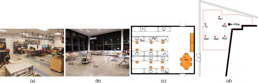
FIGURE 6. Experimental setup and floor plan of two different environments: (a) Laboratory; (b) atrium; (c) laboratory floor plan; (d) atrium
floor plan.
2
where FR (r) = dr2 and fGRx (θ) is (4) for 3GPP antenna model V. NUMERICAL ANALYSIS AND EXPERIMENTAL RESULTS
max
and (5) for ideal sector antenna model. A. TESTBED AND EXPERIMENTAL SCENARIOS
The success probability of Eve due to reflectors P(SNR > In this section we describe our experimental scenarios
β, R̄1 ) is similar to Section III-C. Therefore the probability of to validate the proposed eavesdropping attacker strategies.
Eve to successfully eavesdrop on Alice transmission is given Our numerical analysis also follows the same system and
by the following Corollary 2. environment settings. Our experimental set up consists of
Corollary 2: Given a SNR threshold β, the success proba- three 60 GHz millimeter wave nodes Alice, Bob and Eve.
bility of Eve to overhear Alice transmission is given by (22), All the three nodes use 802.11ad protocol for commu-
as shown at the bottom of this page, nication. We use TP-Link Talon AD7200 [15] routers as
where fGrx (θ) is (4) for 3GPP antenna model and (5) for Alice and Bob. The router is equipped with 802.11ad
ideal sector antenna model. QCA9008-SBD1 module with QCA 9500 chipset from Qual-
From Corollary 2, with active nomadic attack strategy, comm. The router has a 32 element phased array antenna for
the ability of Eve to overhear Alice transmission depends directional communication using 802.11ad protocol. Alice
on Eve’s capability to estimate the LOS sector between is configured as an AP and Bob as a client. To implement
Alice and Bob. Eve’s success probability also depends on the the eavesdropping attacker protocols described in Section III
beamwidth θ1 of Alice antenna beam pattern. Wider the beam and Section IV, an 802.11ad 60 GHz Acer Travelmate
used by Alice, higher will be the probability that Eve’s local- P446-M [28] laptop is used as eavesdropper (Eve). The laptop
ization procedure results in her being in the correct sector has a client version of the module QCA9008-TBD1. The
served by the beam. For narrower beams, localization error laptop is equipped with the same 32 element phased array
in estimating the sector between Alice and Bob will result in antenna that is used in TP-Link Talon AD7200 routers. The
Eve’s gain being drastically reduced. In the worst case, local- laptop uses Wilocity wil6210 wireless driver. Eve is config-
ization error could result in Eve being in the adjacent sector ured to operate in monitor mode using the Wilocity driver
than the actual communication sector between Alice and Bob. to listen to the 802.11ad beacons and sector sweep frames
Also, it should be noted that, similar to opportunistic station- from Alice and Bob. However, the Wilocity firmware does
ary attacker strategy, Eve’s success probability under active not provide signal strength measurements for the data pack-
nomadic attack strategy is enhanced by reflections from the ets overheard between Alice and Bob. Hence, the received
environment. With active nomadic attack strategy, the ability signal power at Eve due to eavesdropping Alice to Bob
for Eve to overhear Alice transmission to Bob is significantly communication is measured using a separate 60 GHz receiver
improved, since Eve with 802.11ad beam searching protocol from VubiQ [16]. The down-converted baseband signal from
estimates the active sector of communication between Alice Vubiq is connected to a CXA N9000A signal analyzer to
and Bob and directly moves to the region. measure the signal power. We deploy our experimental set
Z
P(CEve ) = 1((θEve , rEve ) ∈ A) [FR (r)] s
P G (θ )G (θ) fGrx (θ) (g)dg
gr r= Tx Tx 2 Rx
β 4π
λ σ2
s
Ptx Gtx (θ)Grx (θ)
! −βo
( 4π 2 2
λ ) βσ ρ
−p
r
Ptx Gtx (θ)Grx (θ )
Z −2π λ e 2 1− βo +1 e
( 4π
+ 1((θEve , rEve ) 6 ∈ A)
βo 2 2
1−e λ ) βσ ρ fGrx (θ) (gr )dgr . (22)
gr
VOLUME 7, 2019 70363S. Balakrishnan et al.: Modeling and Analysis of Eavesdropping Attack in 802.11ad mmWave Wireless Networks
TABLE 2. Common parameters used in the simulation.
.
up in two different environments. The first is a laboratory
environment shown in Fig. 6a. The size of the laboratory is
8.5m×9 m. This scenario includes cubicles, tables, chairs, FIGURE 7. Measured sector patterns of TALON AD7200 [31]. (a) Sector 20.
and desktop monitors. Experiments were conducted during (b) Sector 30.
office hours with human mobility that introduces blockages.
The floor plan is shown in Fig. 6c. The second is an atrium experiment, five different position configurations are used for
with glass panels on two sides of the atrium as depicted Alice and Bob. In all the five configurations, the position of
in Fig. 6b and the floor plan is shown in Fig. 6d. The atrium Alice which is referred to as Tx in the floor plan in Fig. 6c
scenario is largely an open space with limited obstructions. and Fig. 6d is fixed as is the case in most practical scenarios
In both the scenarios, the AP is deployed such that it provides where the position of AP is usually fixed. Five positions are
best coverage to Bob. The experiments in the atrium were chosen for Bob which is referred to as Rxi with i specifying
conducted with limited human mobility. configuration index as shown in the Fig. 6c and Fig. 6d. The
position of Eve is randomly chosen in the experimental area
B. EVALUATION ENVIRONMENT for each experiment.
In this section we describe our numerical evaluation method-
ology and experimental validation methodology of our pro- 2) ANTENNA CONFIGURATIONS
posed eavesdropper attack strategy discussed in Section III For the analytical studies, we assume Alice, Bob and Eve
and Section IV. We used MATLAB to analytically evaluate are equipped with directional antenna for communication.
our proposed eavesdropper attacker strategies. Our system We consider two types of antenna model as described in
model consists of Alice and Bob which are legitimate node Section II-C. For both the ideal sector antenna in (1) and
pairs communicating and an eavesdropper Eve. Alice and 3GPP antenna model in (2), the main lobe gain, side lobe
Bob uses 802.11ad based mmWave narrow beam commu- gain and antenna beam width are chosen as 24 dBi, 3 dBi and
nications for communicating with each other. Eve tries to 30◦ , respectively for Alice unless otherwise specified. The
overhear transmissions from Alice using LOS if available mainlobe gain and beamwidth for the analytical studies are
or through reflections from environmental reflectors. It is set according to the specifications of the commercial devices
assumed that Alice and Bob completes beam searching pro- used in our experiments. The TALON AD7200 router which
cedure as per 802.11ad protocol and their beams are perfectly is used as Alice in our experiments has an EIRP of 24 dBi. The
aligned. We also assume that Eve has the same capability as beamwidth for the TALON AD7200 is unspecified in the data
that of Alice and Bob and uses 802.11ad protocol. Locations sheet [30]. The work in [31] experimentally measures the
of Alice, Bob and Eve are randomly chosen in the area. antenna pattern of all the sectors used by TALON AD7200.
The obstacles and reflectors are randomly dropped following From Fig.7, we see the TALON AD7200 routers antenna
the PPP model discussed in Section II. The dimensions of pattern is largely irregular without well defined notion of
the obstacles and reflectors are chosen to depict furnitures, beamwidth and it varies roughly from 30◦ to 60◦ . There-
fixtures and other objects found in a common indoor living fore, for our analytical studies we choose 30◦ beamwidth
room scenario. A list of common parameters used for the for Alice unless otherwise specified. The antenna gain and
analytical validation are shown in Table 1. The carrier fre- beamwidth of Eve is set as 24 dBi and 12◦ to match with the
quency and bandwidth are chosen to match with the carrier WR-15 standard gain horn antenna [32] used by the Vubiq
frequency and bandwidth used by the commercial devices 60 GHz receiver [16] which is used as Eve in our experiments.
in our experimental validation. The reflection loss ρ due to In the experiments, the antenna pattern used by Alice and Eve
reflectors present in the environment is uniformly chosen are determined by the 802.11ad beam searching protocol.
between 2 dB and 23 dB [29].
C. OPPORTUNISTIC STATIONARY ATTACK
1) mmWAVE NODE DISTRIBUTION In this section, we discuss the simulation and experimental
For the analytical evaluations, we consider an evaluation results for opportunistic stationary attacker model discussed
area of 8.5m×9 m depicting an indoor living room as spec- in Section III. Fig. 8 shows the success probability ver-
ified in TGad evaluation methodology document. For our sus SNR for opportunistic stationary attacker model. Fig. 8
70364 VOLUME 7, 2019S. Balakrishnan et al.: Modeling and Analysis of Eavesdropping Attack in 802.11ad mmWave Wireless Networks
FIGURE 8. Success probability versus SNR threshold β for simulation and
experiments in the laboratory and in the atrium.
compares the success probability obtained through analyt-
ical model and experiments in the Atrium and laboratory
environment. The success probability is evaluated for both
the ideal sector antenna pattern in (1) as well for the 3GPP
antenna pattern in (2). For the analytical model, the antenna
pattern of Eve is aligned to the best sector Eve sees from
Alice. The simulations were carried for 10000 trials for
each SNR threshold β and the average success probability
is plotted for different SNR thresholds. From Fig. 8, it is
seen that since the ideal sector antenna model uses constant
gain over the entire mainlobe, the success probability with
ideal sector antenna is higher than the success probability FIGURE 9. Success probability versus SNR threshold β for different
with 3GPP antenna pattern. The eavesdropper has higher antenna beamwidth for (a) 3GPP antenna model and (b) ideal sector
antenna model.
probability to align its beam with ideal sector antenna than
with 3GPP antenna model. Fig. 8 also shows the experimental
success probability in the laboratory environment as well as under 3GPP and ideal sector antenna pattern respectively.
in the atrium. In the atrium cases, it is observed that the With ideal sector antenna pattern, success probability of
experimental success probability is higher than the analytical Eve increases with increasing beamwidth of Alice. With 60◦
success probability due to the fact that the antenna pattern beamwidth Eve has very high probability of eavesdropping
used by commercial 60 GHz 802.11ad routers like TALON even with higher SNR threshold requirements. The eaves-
AD7200 and 802.11ad laptops have irregular beampattern dropping probability reduces drastically when Alice uses
and much higher sidelobes which results in many strong antenna pattern with narrow beamwidths of 3◦ , 7◦ and 10◦ .
reflected paths. Also, the atrium scenario did not have any Success probability for different beamwidths under 3GPP
obstacles and Eve always has clear LOS to either the side antenna model also shows similar trend as that of ideal sector
lobes or to the reflectors in the atrium. Fig. 7a and Fig. 7b antenna model. But the success probability for 3GPP antenna
shows two of the actual measured sector patterns used by model is lower than that of ideal sector pattern as the mainlobe
the TALON AD7200 routers [31]. Antenna pattern used by gain of 3GPP antenna pattern varies with the beam direction.
sectors 20 and 30 have very significant sidelobes that are as Even if Eve is in LOS sector of Alice, Eve will see a lower
strong as the mainlobe. For example, antenna pattern used antenna gain if the boresight angle of Eve is not perfectly
by sector 30 has significantly comparable gains in 60◦ , 170◦ , aligned with Alice.
−60◦ , −120◦ , −140◦ , −165◦ directions. When Alice uses
this sector for transmission to Bob, even if Eve is not in the 2) EFFECT OF EVE’S ANTENNA
LOS of Alice to Bob communication, has higher probability The success probability of Eve to eavesdrop Alice’s com-
to eavesdrop on Alice transmission due to the significant munication varies depending on the antenna used by Eve.
sidelobes and reflections from Alice antenna pattern. If Eve could use a narrow beam width high gain antenna, she
could eavesdrop on Alice’s communication even from longer
1) EFFECT OF ALICE’S ANTENNA distance. Eve could also benefit from weak reflections from
In the opportunistic stationary attacker model, Eve’s prob- ambient reflectors. We experimentally studied the impact of
ability of eavesdropping Alice’s transmission significantly Eve’s antenna beam width and gain on the eavesdropping
increases with the increase in the beamwidth of Alice beam success probability. We conducted experiments in the labora-
pattern. Fig. 9a and Fig. 9b shows Eve’s success probability tory environment shown in Fig. 6c. We fixed Alice and Bob
for antenna beamwidths 3◦ , 7◦ , 10◦ , 20◦ , 30◦ , 40◦ , 50◦ , 60◦ position at position labeled as Tx and Rx3 in Fig. 6c.
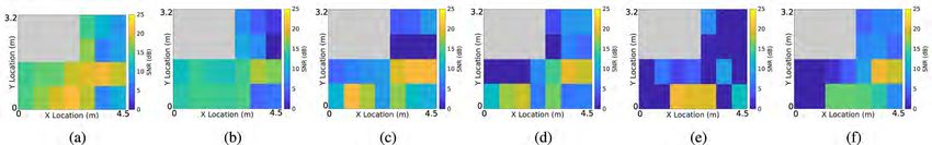
VOLUME 7, 2019 70365S. Balakrishnan et al.: Modeling and Analysis of Eavesdropping Attack in 802.11ad mmWave Wireless Networks
FIGURE 10. SNR of eavesdropped signal from alice. Eve uses an antenna
with (a) 24 dBi gain and 11◦ beam width and (b) 34 dBi gain and 2.5◦ FIGURE 12. Floor plan of the indoor scenario for reflection experiments.
beam width.
experiments for 2 types of Eve’s antenna: (a) 11◦ beam width
and 24 dBi gain and (b) 2.5◦ beam width and 34 dBi gain.
The experiment area floor plan is shown in Fig. 12. Alice and
Bob are placed at the location shown in the floor plan at a
height of 1m. The space behind Alice from (x = 0m, y =
2.4m) to (x = 3m, y = 2.4m) is blocked so Eve can only
point her beam towards the reflector. Alice communicates
to Bob using antenna beampattern 20 shown in Fig. 7a.
We placed the reflectors such that the side lobe between
angle 120◦ and 150◦ of Alice’s beampattern 20 points towards
the reflector. Fig. 13 shows the received SNR at Eve for
FIGURE 11. Success probability versus SNR threshold for different overhearing Alice’s transmission to Bob for different reflec-
antenna gain and beam width of eve. tor types and different antenna beam widths used by Eve.
Our experiments showed that, owing to the irregular beam-
Throughout the experiment Alice to Bob communication patterns of commercial mmWave devices, reflectors such as
sector is fixed at 20. The beam pattern of sector 20 is shown large cardboards, metal plates and computer screens of size
in Fig.7a. We used Vubiq 60 GHz receiver as Eve. For comparable to the beam width of Alice’s side lobe reflects
Eve, we used two directional horn antenna from Pasternack. significant beam. In particular, large cardboards and metal
One with 11◦ half power beam width and 24 dBi gain and plates have many reflection points that could potentially act
another with 2.5◦ half power beam width and 34 dBi gain. as sources of reflected signals for Eve. For an SNR threshold
The experiment area is divided into grids and in each grid of 10 dB, 85% and 65% of eavesdropping area exceeds the
position we focus on the strongest signal direction from Alice SNR threshold at Eve with 2.5◦ antenna, 34 dBi gain and 11◦
and record the SNR. The strongest signal direction could be antenna, 24 dBi gain, respectively for the cardboard reflec-
towards Alice or towards favorable reflectors present in the tor. For the metal reflector, the eavesdropping area reduces
experiment area. Fig. 10a and Fig. 10b shows the SNR of to 50% and 35% for 2.5◦ antenna, 34 dBi gain and 11◦
Alice signal eavesdropped by Eve with 24 dBi and 34 dBi antenna, 24 dBi gain, respectively. Using narrow beam high
gain antenna, respectively. With a higher gain antenna, Eve gain antenna significantly helps Eve to eavesdrop on Alice’s
is able to eavesdrop on Alice signal with higher SNR than signal. On the other hand, smaller reflecting surfaces like
with lower gain antenna. Interestingly at locations behind computer screens reflects beam towards a particular spatial
Alice where Eve has LOS to Alice’s back lobes, the SNR of direction. If Eve is not exactly in the direction of the reflected
overheard communication from Alice is significantly higher signal, her eavesdropped signal SNR significantly decreases.
with 34 dBi antenna. This is due to a stronger signal from the For the same reason, using narrow beam to eavesdrop is not
reflector further amplified by Eve’s high gain antenna. Fig.11 a wise choice for Eve. A wider beam antenna will help Eve
shows the success probability for different SNR thresholds. to collect as much reflected energy as possible even if Eve is
With 34 dBi antenna, the SNR of eavesdropped signal is not exactly in the direction of reflection. The eavesdropping
higher than 15 dB over 90% of the eavesdropped area. On the area for computer screen is 20% and 30% for 2.5◦ antenna,
other hand, with a 24 dBi antenna, the SNR is higher than 34 dBi gain and 11◦ antenna, 24 dBi gain, respectively. Under
15 dB over only 80% of the eavesdropped area. opportunistic stationary attack, even if Eve could not point her
antenna beam towards Alice she could still take advantage
3) EFFECT OF AMBIENT REFLECTORS of the ambient reflectors in the environment, and point her
In this section, we specifically discuss the effect of reflectors antenna beam towards the reflectors.
and Eve’s antenna beam width and gain on her eavesdropping
capabilities. We used a large cardboard of size 0.9m × 0.9m, 4) EFFECT OF DENSITY OF REFLECTORS
a large metal plate of size 0.5m × 1.2m (width × height) As the density of reflectors in the environment increases,
and a 21-inch computer screen as reflectors. We performed the probability of Eve finding an ambient reflector that could
70366 VOLUME 7, 2019You can also read