Moterra NEO Owner's Manual Supplement - Cannondale
←
→
Page content transcription
If your browser does not render page correctly, please read the page content below
Moterra NEO
Owner’s Manual Supplement

READ THIS SUPPLEMENT AND YOUR
CANNONDALE BICYCLE OWNER’S MANUAL.
Both contain important safety information. Keep
both for future reference.
Safety Messages
                      In this supplement, particularly important information
                                 is presented in the following ways:

                            Indicates a hazardous situation which, if
                            not avoided, may result in death or serious
                            injury.

                            NOTICE
                            Indicates special precautions that must
                            be taken to avoid damage.

                           The following symbols are used in this manual:

Symbol        Name                                 Description
 NG
     LI
        -2    NGLI-2 synthetic grease               Apply NGLI-2 synthetic grease.

CR
  B-
       GE
          L   Carbon gel                            Apply carbon gel (friction paste) KF115/

              Medium-strength
 2                                                  Apply Loctite® 242 (blue) or equivalent.
              removable thread lock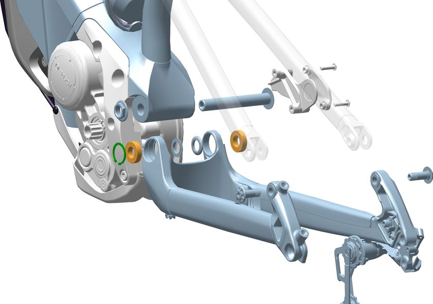
English

 Cannondale Supplements                                               CONTENTS
 This manual is a “supplement” to your Cannondale
 Bicycle Owner’s Manual.
                                                         Safety Information.....................2-5
 This supplement provides additional and important
 model specific safety, maintenance, and technical       Technical Information..............6-19
 information. It may be one of several important
 manuals/supplements for your bike; obtain and           Replacement Parts...................... 20
 read all of them.

 Please contact your Authorized Cannondale Dealer
 immediately if you need a manual or supplement,
 or have a question about your bike. You may also
 contact us using the appropriate country/region/
 location information.

 You can download Adobe Acrobat PDF versions of
 any manual/supplement from our website: http://         Your Cannondale Dealer
 www.cannondale.com.
                                                         To make sure your bike is serviced and maintained
                                                         correctly, and that you protect applicable
                                                         warranties, please coordinate all service and
                                                         maintenance through your Authorized Cannondale
                                                         Dealer.
 Contacting Cannondale
 Cannondale USA                                           NOTICE
                                                          Unauthorized service, maintenance, or repair
 Cycling Sports Group, Inc.                               parts can result in serious damage and void your
 1 Cannondale Way, Wilton CT, 06897, USA                  warranty.
 1-800-726-BIKE (2453)

 Cycling Sports Group Europe B.V
 Mail: Postbus 5100
 Visits: Hanzepoort 27
 7570 GC, OLDENZAAL, Netherlands
 Tel: +41 61 551 14 80
 Fax:+31 54 151 42 40

 International Distributors
 Consult our websIte to identify the
 appropriate Cannondale Dealer for your
 region.

137366 Rev 1.                                        1
2019 Moterra Neo - Owner’s Manual Supplement

                 GENERAL EBIKE SAFETY INFORMATION

 Intended Use                                          Compliance/Regulation
 This model is equipped with an electric
 pedal assist drive system. It is not a moped
 or motorcycle. In EU countries, it is known
 legally as an “EPAC” cycle or Electrically
 Powered Assisted Cycle.                               MAXIMUM ALLOWABLE ASSIST SPEED:
                                                       The drive assist system is limited to a
 The drive assist system consists of a drive           maximum continuous power rating as
 unit, a battery, a computer control, and              idicated in “Specifications.”
 various electronic components (harness
 wires, sensors, and switches). This model             YOU MUST FOLLOW ALL LOCAL LAWS:
 bike does share components common with                It is your responsibility to identify and
 pedal-only bikes.                                     follow all local laws and regulations
                                                       (including fitting your bike with additional
 It is important to know that when the assist          equipment) necessary to comply with
 system is turned ON, the drive unit engages           your state and local laws.
 to provide power only while you are pedaling.
 The amount of power provided by the drive             Ask your local Cannondale Dealer for
 unit depends on your pedaling force and               more information about operating an
 the assistance mode/level you set with the            electrically assisted pedal bicycle in your
 handlebar control unit. At anytime, if you            area.
 stop pedaling, the drive assist will dis-
 engage. In all modes/levels, the drive assist
 system power reduces progressively and                Drive System
 cuts off as the bike reaches a the maximum
 allowable speed. The drive-assist re-engages
 when speed drops below the maximum
 allowable speed as long as the pedals are
                                                       MANUFACTURER’S INSTRUCTIONS - In
 turning.
                                                       addition to this supplement, you must read and
 Whenever the drive assist system is turned            follow the manufacturer’s instructions for all
 OFF, You can pedal the bike normally. The             components of the drive assist system :
 drive system will not engage.
                                                        Drive Unit              Battery
                                                        Display/Control Unit    Charger

  UNDERSTAND YOUR BIKE , DRIVE SYSTEM                  These instructions contain correct operation,
  AND THE INTENDED USE OF BOTH. USING                  service and maintenance information. Drive
  YOUR BIKE THE WRONG WAY IS DANGEROUS.                system instructions can be also be found at
                                                       www.cannondale.com.
  See “Specifications” in this manual for the
  Intended Use of your specific model.

  Please read your Cannondale Bicycle Owner’s
  Manual for more information about Intended
  Use and Conditions 1-5.

  DRIVE SYSTEM: You must follow the
  manufacturer’s instruction for intended use or
  limitation.

137366 Rev 1.                                      2
English

 Operation

  IMPORTANCE OF PRACTICE & RIDER TRAINING - Before you ride this bike, practice riding in a
  safe area free from hazards. Take time to learn to bike’s controls and performance. Practice the
  controls and gain the experience necessary to avoid the many hazards you will encounter while
  riding.
  DO NOT RIDE “HANDS-OFF - Keep you hands on the handlebars when riding the bike. If you
  remove your hands from the handlebar while riding, you can lose control of the bicycle and crash.
  CHANGING THE ASSISTANCE LEVEL WHILE RIDING - Changing the drive assistance level while
  riding will increase or decrease the acceleration of the bike. You should anticipate this change
  in speed and react appropriately depending on the riding conditions. (such as on slippery trails,
  tight turns, or unstable or uneven surfaces). Set assistance level to “ECO” (lowest asist) or “OFF”
  before descending technical trails, (e.g. tight downhill switchbacks).”
  WHEN NOT RIDING - TURN THE DRIVE SYSTEM OFF and REMOVE THE BATTERY , KEY, AND
  CONTROL UNIT AND STORE ALL IN A SECURE AREA TO PREVENT UNAUTHORIZED USE.
  Remove the battery and key when the bike is parked for long periods.
  DO NOT ALLOW CHILDREN TO OPERATE EBIKE. Follow any state or local laws for any
  minimum age restrictions for eBikes.
  ONLY TURN THE DRIVE SYSTEM ON WHEN YOU ARE SEATED WITH YOUR HANDS ON THE
  HANDLEBAR READY TO RIDE.
  EBIKES ARE HEAVIER THAN ORDINARY MOUNTAIN BIKES. This bike has wide bars, and with
  wide tires without a integrated kickstand to hold it parked upright. Always park the bike in a
  suitable safe area away from children, cars or animals that may come into contact with it.
  WEAR A HELMET AND ALL OTHER PROTECTIVE GEAR (GLOVES, PADS, AND CYCLING
  SHOES).

Servicing

  This supplement may include procedures beyond the scope of general mechanical
  aptitude.
  Special tools, skills, and knowledge may be required. Improper mechanical work increases
  the risk of an accident. Any bicycle accident has risk of serious injury, paralysis or death.
  To minimize risk we strongly recommend that owners always have mechanical work
  done by an Authorized Cannondale Dealer.

137366 Rev 1.                                   3
2019 Moterra Neo - Owner’s Manual Supplement

 Modification                                                         No Child Seats or Trailers

                                                                      Child seats and trailers or racks can not be used and
  DO NOT MODIFY THIS BICYCLE/DRIVE SYSTEM/ IN
                                                                      are not allowed to be used with your Cannondale
  ANY WAY FOR ANY REASON.
                                                                      e-bike.
  Doing so can result in severe damage, faulty or
  dangerous operating conditions, or violation of local
  laws.

  Dealers and owners MUST NOT change, alter, or
  modify in any way the original components of the
  bicycle or drive assist system and the specified sizing
  of the attached gear ratios (front/rear chain rings).

  Specifically attempts to “hot-rod” or “improve” the
  speed of the bike are dangerous to the rider.

  Use only specified CANNONDALE and manufacturer
  drive assist service and replacement parts.

 Labeling

                                   EN ISO 4210

       This bike complies with EN 15194,
       EN ISO 4210 - Electrically Power Assisted Cycles (EPAC).

137366 Rev 1.                                                     4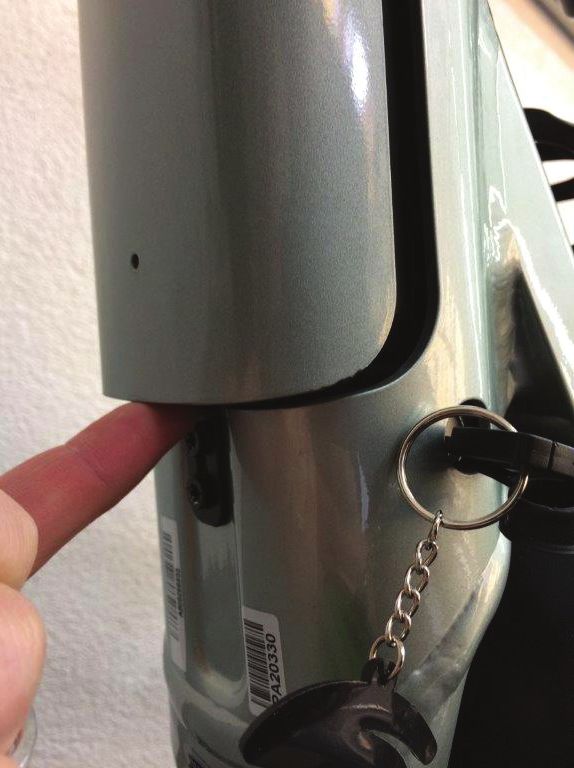
English

                                      IDENTIFICATION

                                                                                  3

                                                                          2
                                                                      7

  5

                                                               1
                                                       6
                                          4                           9

                                                                              8
      The serial number is located on the bottom
      bracket. It is a 7-character barcode (1). Use
      this serial number to register your bike.

          To register your bike: go to the
          Product Registration section of our                                         AB12345
          website at www.cannondale.com

      Record YOUR Serial Number here:

      ________________________________________

 1.    Drive Unit                    6.       Front Chain Ring
 2.    Battery                       7.       Battery Key Lock
 3.    Drive Control Unit            8.       Bike Serial Number/ID
 4.    Speed Sensor (left side)
 5.    Rear Cassette

137366 Rev 1.                                          5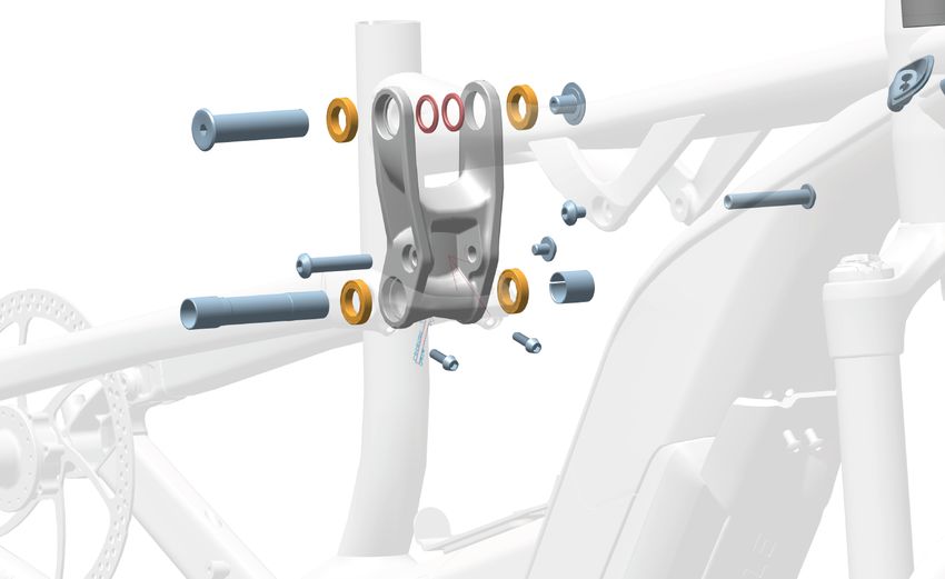
2019 Moterra Neo - Owner’s Manual Supplement

                           TECHNICAL INFORMATION
 Frame Specification

  Item                                         Specification
  Drive System                                 Bosch Performance CX
  Battery                                      Bosch Powertube 500Wh
  Drive-Assist Owners Manual                   https://www.bosch-ebike.com
  Maximum Speed (drive assist)                 25 kph / 20 mph
  Keys (replacement)                           www.abus.com
  Rear Travel                                  130 mm
  Head Tube                                    UPR: 1-1/8 in LWR: 1-1/2 in
  Headset                                      Integrated, 1-1/8 in - 1-1/2 in
  Bottom Bracket: Type/ Width                  Bosch Drive Unit
  Front Derailleur                             N/A
  Seat Post: Dia./Binder                       31.6 mm / 34.9 mm
      Min. Seat Post Insert                    100 mm
      Tire Size x Max. Width                   27.5 in x 2.8 in (measured)
      Max. Fork Length:                        541 mm
  Rear Shock:
                                               210 x 50 mm
  Eye-To-Eye / Stroke / Bushing Width
  Recommended Sag:                             15 mm
  Chain Guide                                  Cannondale Chain Guide
  Brakes: Mount Type /                         RR: Post Mount /180 mm /
  Min/Max Rotor Dia.                           200 mm (SRAM), 203 mm (Shimano)
  Axles: Type / Length                         RR: Syntace TA / 157 x 12 mm
                                               ASTM CONDITION 4,
      Intended Use:
                                               All-Mountain
     Max. Weight Limit:
                                               330 lbs / 150 kg
  Total (rider+all equipment):

137366 Rev 1.                              6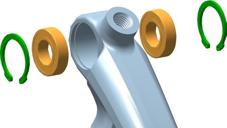
English

  Geometry
                                                             B
                                                                  O
                                                                                    F

                                                              C
                                                                                                   N

                               D            A
                                                        E
                                                                            C

                           J                                                                   L
                                        I                              H
                       K
                                                            75mm

                                                             G                                     M
                                                                      Dimensions = centimeter/inch

         Size                                           S              M                L              XL
   A     Seat Tube Length                               41.0/16.1      44.0/17.3        47.0/18.5      51.5/20.3
   B     Top Tube Horizontal                            58.7/23.1      61.4/24.2        63.8/25.1      66.6/26.2
   C     Top Tube Actual                                52.2/20.6      55.2/21.7        57.8/22.8      61.2/24.1
   D     Head Tube Angle                                66.0°          *                *              *
   E     Seat Tube Angle Effective                      75.0°          *                *              *
   E’    Seat Tube Angle Actual                         67.0°          *                *              *
   F     Standover                                      73.9/29.1      74.9/29.5        75.5/29.7      77.8/30.6
   G     Head Tube Length                               10.0/3.9       11.0/4.3         12.0/4.7       13.0/5.1
   H     Wheelbase                                      118.4/46.6     122.1/48.1       124.7/49.1     127.6/50.3
   I     Front Center                                   73.5/28.9      77.2/30.4        79.7/31.4      82.7/32.6
   J     Chain Stay Length                              45.0/17.7      *                *              *
   K     Bottom Bracket Drop                            1.0/0.4        1.8/0.7          *              *
   L     Bottom Bracket Height                          35.1/13.8      36.2/14.2        *              *
   M     Fork Rake                                      4.4/1.7        5.1/2.0          *              *
   N     Trail                                          11.3/4.4       11.3/4.5         *              *
   O     Stack                                          58.5/23.0      61.9/24.4        62.9/24.7      63.8/25.1
   P     Reach                                          43.0/16.9      44.8/17.6        47.0/18.5      49.5/19.5

 * - Indicates same.

 All Specifications subject to change without notice.

137366 Rev 1.                                           7
2019 Moterra Neo - Owner’s Manual Supplement
Keys
Keys are used to secure the wheel and 1
battery lock mechanism. The drive system,
may be activated by this same key. Please
consult the drive system owner/operator 123
45
manuals to determine.
Please record the key serial number for 2 123
45
future use and key replacement.
If your keys are ever lost or stolen, or you a
would like additonal spares, please contact
the key manufacturer indicated in the 1. Main Key a. Serial Number
“Frame Specifications” in this manual. 2. Spare Key
NOTICE
Don’t ride with key in battery lock. Always remove
the key from the lock after using it. Keys may be
stolen or break off accidentally in the lock. Keep your
spare key in a safe place.
Please Note:
After lots of rides and washing, the battery
lock can become dry and difficult to use. To
maintain, whenever you lubricate your bike
chain, place a few drops of chain oil on the
key insert the key and operate the lock, then
remove and wipe the key clean.
Record YOUR Key Serial Number here:
________________________________________
137366 Rev 1. 8English
Battery Charging Port
The battery charging port is located on the
left side of the bicycle at the top of the down
tube.
The charging port enables the battery to be
charged while installed in the bicycle.
To connect to the charger cable to the port
connector:
1
1. First, familiarize yourself with the safety
information for charging provided by
the drive system manufacturer. And, of
course, the battery must be installed and
in good condition to accept a charge.
2. Place the bike and charger in a secure
area where both will remain undisturbed
while the battery is charged.
3. Lift up the battery port cover.
See Figure 1.
2
4. Attach the charger cable. See Figure 2 & 3.
Follow the manufacturer’s charging
instructions for the duration of charging.
5. Disconnect chargercable from the port
connector and replace cover.
See Figure 4
Make sure cover is seated fully into the
frame opening.
6. Disconnect the charger from its source of 3
power.
4
137366 Rev 1. 92019 Moterra Neo - Owner’s Manual Supplement
Powertube Battery
The drive system battery is housed within
the bicycle downtube. The battery can be
charged via the charge port or removed for
charging.
To remove the battery:
1. On the left side of the bicycle, on the 1
lower end of the downtube, lift the lip of
the key cover and remove the key cover
from the frame key hole. The cover is
tethered; do not try to pull it off the
frame. See Figures 1 & 2.
2. Insert the key into the battery lock and
turn the key counter-clockwise to unlock
the battery latch. Figure 3a.
Push the latch, which releases the battery
out of the battery catch. Figure 3b. 2
3. Slightly tilt and lower the released lower
end of the battery away from the frame.
Figure 4a.
And disengage from the the upper
battery latch. Figure 4b.
4. The battery and attached frame cover is
now out of the frame and can be charged
by connect the battery to the drive
system charger.
3a 3b
4a 4b
137366 Rev 1. 10English
To install the battery:
1. Align the top of the battery with the
upper frame bracket and insert the
battery (cover) attached) into the frame
opening. See Figure 5.
2. Tilt the lower end of the battery into the
lower battery latch until it enages the 5
lock mechanism. See Figure 6..
3. Hold in the battery cover and turn the
key clockwise to engage the battery latch
and lock it.
See Figure 7.
4. Remove the key from the lock and
replace the key cover seal.
Make sure the lip of the seal is fitted
completely around the edge of frame key
6
frame hole. See Figure 8.
7
8
137366 Rev 1. 112019 Moterra Neo - Owner’s Manual Supplement
Shock Link
Shock Link, Remove
1. Top Tube Pivot 7. Shock Bolt
2. Pivot Nut 8. Seat Stay Axle 1. Place the bike in a work stand. Make sure the wheel /
swing arm is supported.
3. Bearing 9. Shim
4. Spacer 10. Pinch Bolts 2. Remove the rear shock bolts and disconnect the shock
5. Link a. gap (seat stay) from the link.
6. Shock Bolt b. slot (shim)
3. Remove the pinch bolts (10) and clean old thread
locking agent from the threads.
4. Insert the driver tool KP169/ (as shown) into of the seat
Service Tool - KP169/ stay axle (8).
Service Tool Cannondale KP169/ is a multi-function tool set
5. Drive out the axle by tapping on the tool with a small
used to remove and install the axle (8) and shim (9). rubber mallet.
The kit also includes bearing driver needed to replace 6. Loosen and remove the pivot nut (2) and remove the
the link and swingarm bearings. It is available from a top tube pivot (1).
Cannondale Dealer.
7. Remove the link and the spacers (4).
Shock Link, Install
1. Clean all parts with a dry lint-free shop towel.
Composite Link Bearing, Install 2. Locate the spacers with the small ends into the link
bearings.
1. Clean outer race of all bearings and link bearing bores
with denatured alcohol and clean cloth to remove any 3. Align and insert the top tube pivot . Tighten the pivot
oil or contamination. nut to the specified torque.
2. Apply a thin bead of Loctite 435 adhesive * around 4. Align and insert the seat stay pivot with the larger end
inside of a bearings bore near the outer edge of the on the drive side. Insert the shim (9) over the axle end
bore. and position the slot (b) opposite the clamp gap (a).
4. Insert a bearing into the bore with adhesive and ensure 5. Re-apply Loctite 242 (blue) to the pinch bolt threads
it is fully seated on the lip (a) in the bore. and tighten to specified torque.
5. Ensure bearing is fully seated in bore.
6. Repeat steps 3-5 for the remaining 3 bearings.
7. Confirm that all 4 bearings are fully seated in each bore.
8. After 45 seconds the adhesive will cure enough for
handling.
9. Wait a 5 minutes before installing link in frame.
137366 Rev 1. 12English
8
9
KP169/
b
b
8
9
a
a
Loctite 435
2 5 Nm
4
1
3
7 6
5
7
6 8 Nm
8
9 Carbon Link:
Install bearings
10 w/Loctite 435 *
Loctite 242 (blue)
5 Nm
* http://tds.henkel.com/tds5/search.asp?t=435
137366 Rev 1. 132019 Moterra Neo - Owner’s Manual Supplement
1 7
3 2
4 Nm
12 Nm
5
6
4 5
8
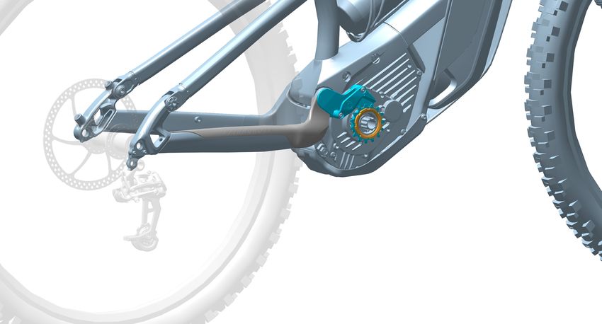
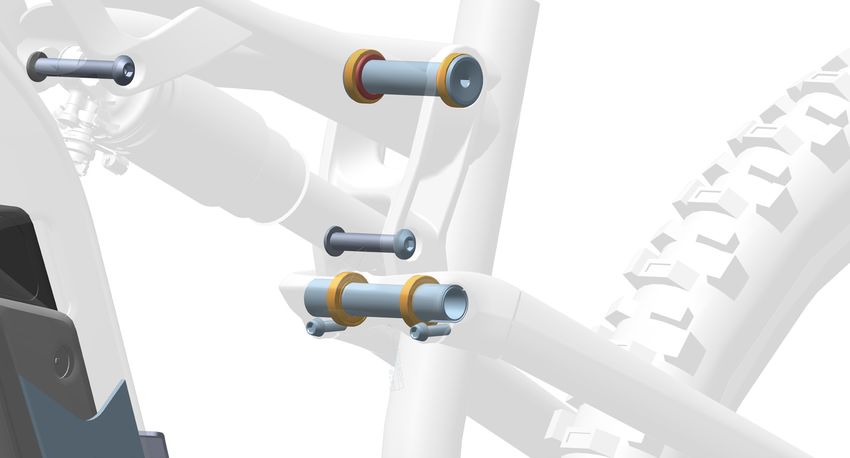
Main Pivot
1. Frame Pivot The main pivot assembly connects the swingarm to
2. Main Pivot Axle the frame. Its should be inspected periodically by a
3. Main Pivot Nut Cannondale Dealer to make sure all the parts are good
4. Ring Clip condition.
5. Bearing Service of worn or damaged parts in this assembly
6. Spacer should be performed by a Cannondale Dealer.
7. Chain Guide Assy.
8. Swing Arm As shown, a significant degree of disassembly is
required.
The main pivot bearings (5) should be renewed
periodically to ensure best performance, or if they
become damaged during use. An indication of damage
would be excessive play or loose feel of the swing arm
connection.
Use Cannondale tool KP169/ bearing drivers to install
and remove the bearings.
The non-drive side bearing (5) is retained by a ring clip
(4).
137366 Rev 1. 14English
8 1
5
Loctite 242 (blue) 4
7 Nm
2
3
6 7
Dropout
1. Seat Stay The dropout bearings (7) should be renewed periodically
2. Swing Arm to ensure best performance, or if they become damaged
3. Dropout (left) during use. An indication of damage would be excessive
4. Spacer play or loose feel of the seat stay dropout connection.
5. Pivot Axle The bearings (see inset) can be inspected without
6. Ring Clip removing them. With the pivots removed, rotate
7. Bearing the installed bearings. The bearings should be free
8. Seat stay end of corrosion, fixed firmly in the dropout and rotate
smoothly without a gritty or loose feel.
It is best practice to renew all the parts ring clips (6),
bearings (7), pivots (5) and spacers (4) with new ones
when service is required. The bearing pairs in each
dropout are retained by two ring clips which are seated
in a groove.
The small end of the spacers (4) fit into the bearings
before connection of the seat stay ends (8).
137366 Rev 1. 152019 Moterra Neo - Owner’s Manual Supplement
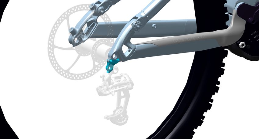
Rear Derailleur Hanger
3
1. RD Hanger 3. Housing Guide
2. Screws
2
Anytime the RD Hanger is replaced due to damage or a
crash, clean the dropout and also check for any damage. 2 Nm
1 Loctite 242
The flexible housing guide (3) is an added part enclosing (blue)
the internally routed RD housing/cable. It spans the
housing section between the chain stay opening the
connection to the rear derailleur. The guide is necessary
to best shifting performance. Be sure to replace it if it is
removed when servicing the rear derailleur.
2
4 Nm
1
20-25 Nm
4
3
Chain Stay Protector / Chain Guide / Front Chain Ring
The following items should be inspected often to make sure they are securely mounted and in good condition and if
damaged, have them replaced by your Cannondale Dealer:
1. Chain Stay Protector - Prevents chain movement from damaging the chain stay.
2. Chain Guide - Retains the chain.
3. Front Chain Ring
4. Chain Ring Nut
DO NOT RIDE WITH A MISSING OR DAMAGED CHAIN
GUIDE.
137366 Rev 1. 16English
Rear Shock
SAG
15 mm
Set Up
1. Set the air pressure according to for you body
weight. Follow the shock manufacturer’s instruction SELECT ONLY COMPATIBLE SHOCKS AND FORKS
for pressurizing the shock. FOR YOUR BIKE. DO NOT MODIFY YOUR BIKE IN ANY
WAY TO MOUNT ONE. HAVE YOUR SHOCK OR FORK
2. Slide the O-ring against the shock wiper seal. INSTALLED BY A PROFESSIONAL BIKE MECHANIC
3. Sit on the bike in a normal riding position with your • Riding with the wrong rear shock can
hands on the handlebar and feet on the pedals so damage the frame. You could have a
that your weight compresses the rear shock. serious accident. Make sure the total
4. Measure the SAG. Adjust the air pressure in the travel, eye-to-eye length, and stroke length
shock to achieve the correct SAG measurement. of the rear shock you select meet the
SPECIFICATIONS listed in this manual.
Add air to decrease sag.
• When selecting different shocks or forks for
Release air to increase sag. your bike, make sure that the shock or fork
you select is compatible with your bike’s
Recommended Sag 30% design and how you will use your bike.
YOU CAN BE YOU SERIOUSLY INJURED, PARALYZED
OR KILLED IF YOU IGNORE THESE WARNINGS.
NOTICE
Mount the shock as shown.
137366 Rev 1. 172019 Moterra Neo - Owner’s Manual Supplement
REPLACEMENT PARTS
A
A
A 2 A
7 N·m
E
2
5 N·m C 8 N·m
2
7 N·m
F
2 L
157 x 12mm B
10 N·m I 4 N·m
B
G N
M4 X 12mm G
LI A
-2
2 N
M4 X 13mm
2 N·m H
N
G
2
LI
-2
12 N·m
D
A B
ID Part Number Description ID Part Number Description
A CK3067U10OS Moterra Link Hardware BLK Brake Adapter Post Mount 180
KP176/X
mm
B CK3047U00OS Moterra Pivot Bearings
Brake Adapter Post Mount 185
C CK3057M00OS Moterra Shock Mount Hardware I KP177/X
mm
D CK3037U10OS Moterra Chainstay Protector BLK
Brake Adapter Post Mount 203
KP178/X
E CK3297U00OS Moterra CRB Link, w/brgs mm
F K83037 Syntace Thru Axle X12 157x12
G KP173/ Derailleur Hanger TA ST DS 026
H KP312/ Open Oval Grommet (QTY 10)
137366 Rev 1. 18English
J
Q
A 34.9 mm
K
5 N·m
A
1 N·m
8 N·m
m
C
L
4 N·m
R
P
N
S
25 N·m
2
2 N·m
M
18 N·m 9 N·m
2
9 N·m
ID Part Number Description ID Part Number Description
J KP388/ Seatbinder MTN Bolt 34.9 Battery Cover DT Bottom Exit
K3425910
SGG
K KP169/ Tool Jekyll Pivot
Battery Cover DT Bottom Exit
L CK2017U10OS Moterra Chainguide BLK S K3425920
GRA
M CK3017U10OS Moterra Skid Plate BLK
Battery Cover DT Bottom Exit
K3425930
N CK2047U00OS Moterra Sprocket and Lockring BPL
O KP456/ Modular Cable Guides HT Headset Integrated Headshok
-- KP205/
To Taper
P K34249 Battery Key Seal
Q K34159 Charge Port Cover PT
R K32089 DT Cable Guide Internal Channel
137366 Rev 1. 192019 Moterra Neo - Owner’s Manual Supplement
MAINTENANCE
The following table lists only supplemental maintenance items. Please consult your Cannondale Bicycle Owner’s Manual
for more information on basic bike maintenance. Consult with your Cannondale Dealer to create a complete maintenance
program for your riding style, components, and conditions of use. Follow the maintenance recommendations given by the
component manufacturer’s for the various non-Cannondale parts of your bike.
CHECK THE FOLLOWING BEFORE EACH RIDE:
• Make sure the battery is fully charged and locked securely in position on the bicycle.
• Check tire pressure and wheel condition.
• Check the drive chain condition. Make sure it is clean and well-lubricated. Chain wear is greater compared with
pedal only bikes. This requires frequent inspection and replacement.
• Check the bicycle brakes, make sure they are working well. Brake system pad and disc wear is greater compared
with pedal only bikes. This requires frequent inspection and replacement.
• Inspect condition of electrical cables (i.e. Kinks free, no signs of abrasive wear)
• Test the drive assist system, make sure the drive system functions normally.
• If your eBike model was equipped a lighting system, brake lights, headlights, and number plate illumination, make
sure these lights are each functioning normally. Make sure the number plate is clean and readable.
IF YOU FIND ANY DAMAGE, DO NOT RIDE THE BIKE, CONTACT YOUR CANNONDALE DEALER.
TO BE PERFORMED BY CANNONDALE DEALER :
Recommended after the first 150 km, bring your bike to your Cannondale Dealer for an initial check-up. It should include
checks of the drive assist system, drive chain condition, proper shifting, accessories, wheels and tire condition, brakes, etc.
This visit will help you establish a schedule for repeated visits appropriate for how and where you ride.
Every 1000 km, bring your bike in to your Cannondale Dealer for a regular detailed inspection, adjustment, and
replacement of wear items across the entire bike. Electrically powered assist cycle (electric bikes) can wear out wheels,
tires, drive chain, brakes, more quickly.
ANY PART OF A POORLY MAINTAINED BIKE CAN BREAK OR MALFUNCTION LEADING TO AN ACCIDENT WHERE YOU
CAN BE KILLED, SEVERELY INJURED OR PARALYZED.
Please ask your Cannondale Dealer to help you develop a complete maintenance program, a program which includes a list
of the parts on your bike for YOU to check regularly. Frequent checks are necessary to identify the problems that can lead
to an accident.
137366 Rev 1. 20English
WWW.CANNONDALE.COM
© 2019 Cycling Sports Group
2019 Moterra NEO Owner’s Manual Supplement
137366 Rev. 1

 CANNONDALE USA               CANNONDALE EUROPE                   CANNONDALE UK
 Cycling Sports Group, Inc.   Cycling Sports Group Europe, B.V.   Cycling Sports Group
 1 Cannondale Way,            Mail: Postbus 5100                  Vantage Way, The Fulcrum,
 Wilton CT, 06897, USA        Visits: Hanzeport 27                Poole, Dorset, BH12 4NU
 1-800-726-BIKE (2453)        7575 DB, Oldenzaal Netherlands      +44 (0)1202732288
 www.cannondale.com                                               sales@cyclingsportsgroup.
                                                                  co.uk
You can also read