MSI Safety PLCs and safety relays - Leuze electronic
←
→
Page content transcription
If your browser does not render page correctly, please read the page content below
MSI
Safety PLCs
and safety relays

www.leuze.com
SAFE
CONTROLS
AND RELAYS
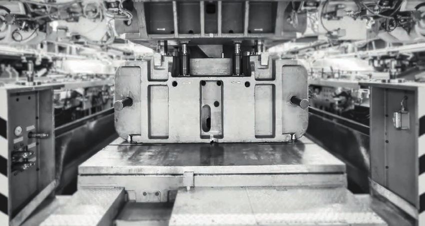
MSI safety PLCs and relays ensure efficient integration of all safety
devices in the machine control.
Regardless of whether you would like to integrate safety
sensors, switches or command devices in the safety circuit of
the machine control: the MSI safety PLCs and safety relays
ensure efficient integration of all safety devices.
SAFETY PLCS
For small to medium-size machines, compact safety controls
are increasingly being used for monitoring the safety circuit.
Thanks to simple commissioning, flexible configuration
options and broad, on-board functionality, the MSI 400
programmable safety PLCs are the optimum system solution
here.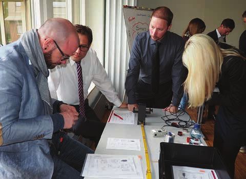
COMPLETE SOLUTIONS
THROUGH SAFETY SENSORS
Together with our wide range of safety switches and
sensors, we offer complete solutions for guarding
machines and systems. Services covering all aspects of
machine safety provide you with support during imple-
mentation.
Light curtains
Photoelectric sensors
(single and multi-beam)
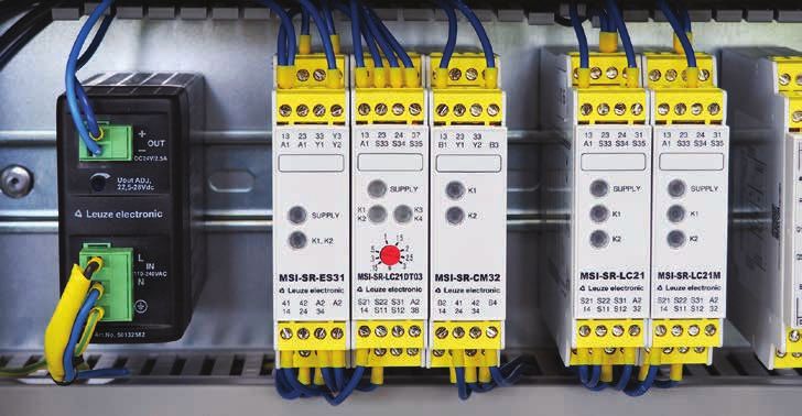
SAFETY RELAYS
For individual sensors, safety relays offer integration with Laser scanners
minimum effort. Our extensive product range of individually
tailored and universal devices offers efficient solutions for
every requirement.
Switch
All modules of the MSI series offer flexible connection
technology and are available with either screw or spring-cage
terminals. For you, this means optimum adaptation to your Proximity sensors
installation requirements and simple replacement of the
devices, e.g., should servicing be required.
Guard interlockings
Command devices
CONTROLLING
YOUR EFFICIENCY IS
THIS SIMPLE
Our MSI control modules and matching add-ons provide
solutions for a wide variety of different applications.
YOU DECIDE WHICH MODEL MSI 410
BEST SUITS YOUR TASK USB interface
20 inputs
The safety PLCs of the MSI 400 series provide 4 outputs
efficient solutions for integrating multiple safety
sensors in machines and systems. The compact MSI 420
design and the integrated Ethernet interface save USB and Ethernet interface
space in the switch cabinet. In addition, the 16 inputs
optional extension modules allow you to adapt the 4 outputs
number of inputs and outputs flexibly to your 4 configurable I/Os
specific requirements. Configuration and commis-
sioning is quick and easy using our MSI.designer MSI 430
programming software. Industrial Ethernet protocols
USB and Ethernet interface
16 inputs
4 outputs
4 configurable I/Os
F50 function package
Function blocks for press control
Standstill monitoring and safely reduced speed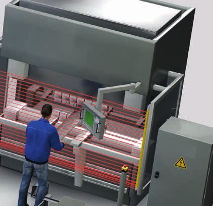
think modular. integrated connectivity.
Perfect start Whether with the integrated industrial Ethernet
The different basic modules of the MSI 400 protocols or the fieldbus gateways: the MSI 400
family are customized entry-level devices which safety PLCs are easy to integrate in industrial
can be extended flexibly. Though they measure networks.
just 45 mm, even the industrial Ethernet
protocols are optionally integrated in the base Ethernet interface and
module. industrial Ethernet protocols
measuring just 45 mm.
Modularly expandable
The I/O extension modules allow modular
expansion to up to 116 secure inputs and 56
secure outputs – ideal for safeguarding large
machines and systems.
45 mm
Gateway modules
for integration in other fieldbuses.
Flexible connection technologies
All modules are available with either pluggable
screw-type terminals or with spring-force/
push-in terminals – this means even better
adaptation to your installation requirements.
Always quickly connected
Integrated USB and Ethernet interfaces enable
flexible access to the system. As a result, status
and diagnostic information is available quickly
during configuration and operation.
easy handling. power reserve.
Removable program memory 300 function blocks
The removable program memory in SD-card Up to 300 function blocks are available for each
format, which can be accessed on the front project. The inputs and outputs can be freely
side, offers large memory space for application assigned for the function blocks. As a result,
programs. Handling of the projects is thereby simple solutions can be found for even more
simplified, saving a great deal of time during complex safety tasks.
commissioning, duplication and should servicing
be required. The cover fastened to the control
protects the memory from unintended removal.
Maximum switching power
Available at each output of the system is 4A of
wear-free switching power. In certain applica-
tions, this offers an efficient alternative to
contactors and relays, e.g., for the control of
pneumatic components.
Optical function indicator via LED
All inputs and outputs of the system feature
clearly assigned LED indicators located above
the connections. These are supplemented with
other LEDs for displaying the module status.
As a result, the operating state of a system can
be identified quickly and unmistakably.
EFFICIENT
PROGRAMMING
IS THIS EASY
With the graphical user interface of the MSI.designer software,
all MSI devices can be programmed very quickly.
MSI .designer
REACH YOUR GOAL QUICKLY WITH
EASY PROGRAMMING
With the new MSI.designer programming tool, you can create In addition to the comfortable simulation on a PC, the
projects for the MSI safety PLCs easily and efficiently. MSI 400 also features a force mode, with which you can
The license-free software supports you during the creation, assign the inputs fixed state values. This enables the targeted
testing and documentation of projects. For logic program- testing of processes directly on the machine. As a result,
ming, an extensive library of certified function blocks is you are ideally prepared for all situations.
available. These can be arbitrarily arranged on freely defin-
able logic pages by means of drag & drop. In addition, MSI. Simple logic programming
designer offers a great deal of flexibility for the creation and Simulation and logic analysis for testing the
management of user elements. Programs can be created safety function right from a PC
very quickly through the direct use of sensors and actuators Force mode for detailed function tests
in the logic editor. The connection with the inputs and Configurable report for professional and
outputs of the modules takes place automatically here. well-organized documentation
Online diagnosis for a fast state overview,
including remote maintenance
GRAPHIC –
INTUITIVE –
EASY

INTUITIVE PROGRAMMING                                           CREATE LOGIC QUICKLY

More than 40 certified function modules are available for       It couldn’t be faster: sensors and actuators can be used
programming the logic. The intuitive operation allows           directly in the logic editor and connected to a function block
programs to be set up quickly. The summary of function          in the same step. MSI.designer thereby automatically assigns
blocks and arrangement on freely definable pages ensure a       the elements to the inputs and outputs of the modules. If
good overview, even with complex projects.                      necessary, the assignment can be optimized freely at any
                                                                time and across modules.

FREELY DESIGN VIEWS                                             PROTECT KNOW-HOW

Everyone works differently. For this reason, MSI.designer       Expand the predefined libraries if necessary with applica-
offers freely arrangeable windows. Whether across multiple      tion-specific sensors and function blocks. The project and the
monitors or docked individually, you always see the elements    function blocks can be protected on various levels by means
that optimally support your work. It is even possible to view   of passwords. With the flexible user management, you can
multiple logic pages in parallel.                               adapt the access rights to the respective user.
INTEGRATED SIMULATION                                            PROFESSIONAL REPORTS

The simulation function and the integrated logic analyzer        The documentation function summarizes all project informa-
allow the programmed functions to be checked right from a        tion in a detailed, well-structured report. The report can be
PC. Any necessary modifications are already performed in         configured by the user and thereby provides an important
the office, and not in the installation area on the machine.     part of the directive-compliant documentation for a machine
This saves considerable time during commissioning on site.       at the press of a button.

TRANSFER IMPORTANT DATA                                          FAST ONLINE DIAGNOSIS

All industrial Ethernet and fieldbus protocols are easy to use   The integrated online diagnosis and the system logbook
thanks to the comfortable configuration.                         provide a quick overview of the system status. Possible
                                                                 problems can thereby be quickly localized. Solutions for
                                                                 remote maintenance can also be implemented without
                                                                 additional effort, thereby often eliminating the need for
                                                                 expensive maintenance work.
BASE MODULES, GATEWAYS AND I/O EXTENSIONS

                           MSI 410                         MSI 420                             MSI 430

Device type / function                                                 Safety PLC

Inputs/outputs             20 inputs / 4 outputs           16 inputs / 4 outputs / 4 configurable I/Os

Test outputs                                                   4 (4 test signal generators)

Cat./performance level
                                                                         4 / PL e
(EN ISO 13849-1)

Safety Integrity Level
                                                                     SIL 3 / SILCL 3
(IEC 61508/EN IEC 62061)

Interfaces                 USB mini                                               USB mini, Ethernet TCP/IP

                                                                                               Modbus TCP
Fieldbus protocols         –                               –                                   Profinet IO
                                                                                               EtherNet/IP

                           Configuration                   Configuration                       Configuration
Interface                  Diagnostics via PC              Diagnostics via PC                  Diagnostics via PC
functionality                                              Diagnostics via PLC                 Diagnostics via PLC
                                                                                               Gateway functionality

Maximum number of
                                                                   12 I/O extensions
extension modules /
                                                                      2 gateways
gateways

Configuration                                      MSI.designer configuration software, license-free

Function blocks                                        300 blocks per project, free assignment

Program memory                                         Exchangeable, SD card format, 512 MB

                                                         24 LEDs – green (1x for each I/O)
Function indicator
                                                   4 LEDs – green / red / yellow for module status

Maximum switching power
                                                                 4 A, short-circuit proof
per output

Supply voltage                                                  24 V DC (16.8 … 30 VDC)

Power consumption                                                         3.5 W

Dimensions (W × H × D)                                             45 × 96 × 115 mm

Ambient temperature,
                                                                      –25 ... +65 °C
operation

Certifications                                                         TÜV, CULUS
MSI-FB-ETHERCAT MSI-FB-PROFIBUS MSI-FB-CANOPEN
Device type / function Gateway
Interfaces 2 × RJ45 sockets 1 × RS485 (Sub-D, 9-pin) Screw terminals, 5-pin
Fieldbus protocols EtherCAT Profibus-DP CANopen
Data transmission rate 100 Mbit/s 12 Mbit/s up to 1 Mbit/s
Function indicators 5 LEDs 3 LEDs 3 LEDs
Supply voltage 24 VDC (16.8 … 30 VDC) via MSI 400 base module, internal bus
Power consumption max. 2.4 W
Ambient temp., operation –25 ... +55 °C
Dimensions (W × H × D) 22.5 × 96.5 × 121 mm
MSI-EM-I8 MSI-EM-I084 MSI-EM-I084NP
Device type / function Safe extension module Non-safe ext. module
4 inputs / 4 outputs /
Inputs/outputs 8 inputs 8 inputs / 4 outputs
4 configurable I/Os
Test outputs 8 (2 test signal generators) 2 (2 test signal generators) –
Cat. / Performance Level 4 / PL e –
Safety Integrity Level SIL 3 / SILCL –
8 LEDs (1 × per I) 12 LEDs (1 × per I/O)
Function indicator
1 LED for module status 1 LED for module status
Maximum switching power
– 4A 0.5 A
per output
Supply voltage 24 VDC (16.8 … 30 VDC)
Power consumption max. 1.4 W max. 1.1 W Max. 0.5 W
Dimensions (W × H × D) 22.5 × 93.7 × 120.8 mm
Ambient temp., operation –25 ... +65 °C
Certifications TÜV, CULUS TÜV, CULUS C
ULUSCOMPACT
SAFETY FOR
YOUR APPLICATION
Our extensive range of safety relays always offers the
right link between safety device and machine.
COMPACT AND SAFE
For the fast integration of individual safety sensors in The applications range from the monitoring of simple
the safety circuit of machines and systems, the components, such as E-Stops or safety switches, to the
compact and reliable safety relays offer the right integration of optoelectronic sensors, the implementa-
solution. tion of time-delayed applications or the standstill
monitoring of motors.
Available in the product range are both evaluation units
that are specifically tailored to various sensor types All relays are available with either pluggable screw
and technologies as well as units that can be used terminals or with spring-cage terminals. For the user,
universally. this means flexibility during installation and allows
devices to be quickly exchanged should service be
necessary. Evaluation units Evaluation units with time function
For the various safety switches, sensors and These relays control, e.g., safe stopping for
command devices, both custom as well as applications with stop category 1 with time
universal evaluation units are available. delays up to 3 sec. or up to 30 sec.
Contact extensions Standstill monitoring
The contact-extension relays are suitable both The safe monitoring of standstill or low speed is
for simple output extension for OSSDs as well performed by evaluating the pulses from
as for contact multiplication for evaluation units incremental transmitters or proximity switches.
or safety PLCs. It is used, e.g., to release guard interlocks or to
monitor during setup mode.THE RIGHT
SAFETY RELAY
AT A GLANCE
Here, you can quickly and easily find the right link
between sensor and machine.
Sensor / application Restart Contacts Additional Performance Product
Manual / NO / functions Level
automatic NC
Evaluation units
1/1 PL c MSI-SR-2H1
2/1 PL e MSI-SR-2H21
M/A 2/– PL d MSI-SR-ES20
M/A 3/1 PL e MSI-SR-ES31
M/A 2/1 PL e MSI-MC310
M/A 2/– PL e MSI-MC311
M/A 2/1 PL e MSI-SR-LC21
–/A 3/1 PL e MSI-SR-LC31AR
M/– 3/1 PL e MSI-SR-LC31MR
M/A 3/1 PL e MSI-SR4
2 x sensor
M/A 2/– PL e MSI-SR5
inputs
M/A 2/1 PL e MSI-SR-LC21M
Evaluation units with time function
M/A 2/– ≤ 3 s/1 contact PL e / d MSI-SR-LC21DT03
M/A 2/– ≤ 30 s/1 contact PL e / d MSI-SR-LC21DT30
M/A 2/– ≤ 30 s/2 contacts PL e MSI-DT30Two-hand Safety
Safety PS mat Contact extension
control solenoid switches
Protective sensors / Type 2 safety sensor,
E-Stop Standstill monitoring
safety light curtains testable
Safety switches and Safety laser Type 4 safety sensor,
Time delay
safety locking devices scanners testable
Sensor / application Restart Contacts Additional Performance Product
Manual / NO / functions Level
automatic NC
Monitoring of standstill / low speed
2/2
M/A ≤ 99 Hz PL e MSI-SR-SM42OS
semiconductor
Contact extensions
A/– 2/1 PL e MSI-RM2
OSSD output extension
A/– 3/2 PL e MSI-SR-CM32
A/– 4/3 PL d MSI-SR-CM43
A/– 5/2 PL e MSI-CM52
A/– 2 x (2 / 1) PL e MSI-SR-CM42R
A/– 4/3 = 3s PL d MSI-SR-CM43DT03
Evaluation units for periodic testing
A/M 2/2 PL c MSI-TR1
A/M 2/2 130 ms filter PL c MSI-TR2
A/M 2/2 =0.6 s/1 signal PL c MSI-TS
A/M 2/2 PL e MSI-TRM
Muting controller (field module)
–/M OSSD outputs PL e MSI-MD-FBEVALUATION UNITS
MSI-SR-ES20 MSI-SR-ES31 MSI-MC310 / 311
Device type / function Evaluation unit Evaluation unit Evaluation unit
E-STOP E-STOP
Sensors / application Safety switches Safety switches Safety solenoid switches
with relay contacts with relay contacts
Special function – – –
Cat./performance level
3 / PL d 4 / PL e 4 / PL e
(EN ISO 13849-1)
Safety Integrity Level
SIL 2 / SILCL 2 SIL 3 / SILCL 3 –
(IEC 61508/EN IEC 62061)
Number of release
2 3 2
contacts (NO contact)
Number of signal contacts MC 310: 1
– 1
(NC contact) MC 311: –
MC 310: 1 NC, 1 NO
Inputs / actuation 1- or 2-channel 1- or 2-channel
MC 311: 2 NC
Start, restart Automatic, manual Automatic, manual Automatic, manual
Contactor monitoring
X X X
(EDM)
Function indicator 2 LEDs 2 LEDs 3 LEDs
Regression delay 70 ms 60 ms 20 ms
Max. continuous current 6A 8A 3A
per path
Mech. Life expectancy 1 × 10⁷ 1 × 10⁷ 1 × 10⁷
Ambient temp., operation MC 310: 0 ... +55 °C
–25 ... +55 °C –25 ... +55 °C
MC 311: –5 ... +55 °C
Dimensions with screw
96.5 × 22.5 × 91.5 mm 96.5 × 22.5 × 107.6 mm 99.5 × 22.5 × 113.6 mm
terminals (W × H × D)
Certifications TÜV, CULUS DGUV, CULUS TÜV, CULUS
A1 A2 Y1 Y2 13 23 A1 A2 Y1 Y2 Y3 13 23 33 41 A1 S11 S12 22 S33 S34 13 23 31
SUPPLY
RESET K1 RESET K1 CH1 CH2 K1
Functions overview K2 K2
CONTROL-LOGIC
K2
SUPPLY CONTROL-LOGIC SUPPLY CONTROL-LOGIC RESET
14 24 14 24 34 42 A2 OUT SR A 14 24 32MSI-SR-2H1 MSI-SR-2H21 MSI-SR-LC21 MSI-SR-LC21M MSI-SR-LC31MR MSI-SR-LC31AR
Evaluation unit Evaluation unit Evaluation unit Evaluation unit
E-STOP
E-STOP
Safety switches:
Safety switches:
- with relay contacts
- with relay contacts
Two-hand control devices Two-hand control devices - with OSSD outputs
- with OSSD outputs
(type III A, EN 574) (type III C, EN 574) - with magnetic contacts
- with magnetic contacts
Safety light barriers
Safety light barriers
Safety laser scanner
Safety laser scanner
LC21M: 4-conductor PS mat
– – – –
1 / PL c 4 / PL e 4 / PL e 4 / PL e
SIL 1 / SILCL 1 SIL 3 / SILCL 3 SIL 3 / SILCL 3 SIL 3 / SILCL 3
1 (change-over contact) 2 2 3
1 (change-over contact) 1 1 1
2-channel (1 NC and
1-channel (1 NC, 1 NO) 1- or 2-channel 1- or 2-channel
1 NO per channel)
Through synchronous actuation Through synchronous actuation Automatic, manual Manual Automatic
– X X X
2 LEDs 3 LEDs 3 LEDs 3 LEDs
20 ms 50 ms 25 ms 10 ms
5A 6A 6A 8A
1 × 10⁷ 1 × 10⁷ 1 × 10⁷ 1 × 10⁷
–25 ... +55 °C –25 ... +55 °C –25 ... +55 °C –25 ... +55 °C
96.5 × 22.5 × 91.5 mm 96.5 × 22.5 × 114 mm 96.5 × 22.5 × 114 mm 96.5 × 22.5 × 114 mm
TÜV, CULUS DGUV, CULUS DGUV, CULUS TÜV, CULUS
A1 A2 T12 T13 12 14 A1 A2 Y1 Y2 Y11 Y12 Y14 13 23 31 A1 A2 S34 S35 13 23 31 A1 A2 S34 13 23 33 41
FEEDBACK CHANNEL 1 K1 RESET RESET
K1 K1 K1
CONTROL-LOGIC CONTROL-LOGIC CONTROL-LOGIC
K2 K2 K2
CH
+ 1 +CH 2– CH
SUPPLY CONTROL-LOGIC CHANNEL 2 SUPPLY SUPPLY + 1 +CH 2–
– + + – +
T11 11 Y21Y22 Y24 14 24 32 S21S11S33 S12 S31 S22 14 24 32 S21 S11 S12 S52 S22 14 24 34 42EVALUATION UNITS / WITH TIME FUNCTION,
STANDSTILL MONITORING, OUTPUT EXTENSION FOR OSSDS
MSI-SR-4 MSI-SR-5 MSI-SR-SM42OS
Monitoring of standstill
Device type / function Evaluation unit Evaluation unit
and low speed
E-STOP E-STOP
Safety switches: Safety switches:
- with relay contacts - with relay contacts Proximity switches
Sensors / application - with OSSD outputs - with OSSD outputs A / B incremental transmitters,
- with magnetic contacts - with magnetic contacts HTL
Safety light barriers Safety light barriers
Safety laser scanner Safety laser scanner
Parallel evaluation of Speed limit / monitoring frequency
Special function –
2 sensors 0.5 – 99 Hz
Cat./performance level
4 / PL e 4 / PL e 4 / PL e
(EN ISO 13849-1)
Safety Integrity Level
SIL 3 / SILCL 3 SIL 3 / SILCL 3 SIL 3 / SILCL 3
(IEC 61508/EN IEC 62061)
Number of release
3 2 2 (semiconductor)
contacts (NO contact)
Number of signal contacts
1 – 2 (semiconductor)
(NC contact)
Inputs / actuation 1- or 2-channel 2 x (1- or 2-channel) 1 or 2 sensors / encoders
Start, restart Automatic, manual Automatic, manual Automatic, manual
Contactor monitoring X X X
(EDM)
Function indicator 4 LEDs 4 LEDs 12 LEDs
Regression delay 10 ms 10 ms 12 ms + 1,6 / fST
Max. continuous current 3A 2A 2A
per path
Mech. Life expectancy 1 × 10⁷ 1 × 10⁷ Semiconductor, free from wear
Ambient temp., operation 0 ... +55 °C 0 ... +55 °C –25 ... +55 °C
Dimensions with screw
99.5 × 22.5 × 111.5 mm 99.5 × 22.5 × 111.5 mm 96.5 × 22.5 × 121 mm
terminals (W × H × D)
Certifications TÜV, CULUS TÜV, CULUS TÜV, CULUS
RES-O
RES-I
S12
S12
S11
A1 S33 S34 S35 S31 S22 13 23 33 41 A1 14 29 31 I1 I2 I3 I4 S1 S2 I5 I6
f monitoring
+ + – + + COMP MODE /
CH1 K1 K1 f setting
CH1
SUPPLY
RESET
SUPPLY
RESET
Functions overview & Reset
CH2 K2 CH2 ≥1
– – + + K2
A2 S12 14 24 34 42 A2 22 30 32 Q1 Q2 Q3 Q4 X1 X2 A1 A2
S22
S22
S21MSI-SR-LC21DT03/30 MSI-DT-30 MSI-RM2 MSI-SR-CM32
Evaluation unit Evaluation unit
Output extension for OSSDs Output extension for OSSDs
with time delay with time delay
E-STOP E-STOP
Safety switches: Safety switches: Safety light barriers Safety light barriers
- with relay contacts - with relay contacts Safety laser scanner Safety laser scanner
- with OSSD outputs - with OSSD outputs Safety switches: Safety switches:
Safety light barriers Safety light barriers - with OSSD outputs - with OSSD outputs
Safety laser scanner Safety laser scanner
DT03: delay: 0.15 – 3 s
Delay: 0.1 – 30 s – –
DT30: delay: 1.5 – 30 s
4 / PL e 4 / PL e 4 / PL e 4 / PL e
(3 / PL d for delayed contact)
SIL 3 / SILCL 3 SIL 3 / SILCL 3 SIL 3 / SILCL 3 SIL 3 / SILCL 3
(2 / SILCL 2 for delayed contact)
2 + 1 delayed 2 + 2 delayed 2 (change-over contact) 3
– – 1 2
1- or 2-channel 1- or 2-channel 2-channel OSSDs 2-channel OSSDs
Automatic, manual Automatic, manual Automatic Automatic
X X – –
3 LEDs 3 LEDs 2 LEDs 2 LEDs
25 ms 20 ms 10 ms 20 ms
6A 6A 3A 6A
1 × 10⁷ 1 × 10⁷ 1 × 10⁷ 1 × 10⁷
–25 ... +55 °C –20 ... +55 °C 0 ... +50 °C –25 ... +55 °C
96.5 × 22.5 × 114 mm 99.5 × 22.5 × 111.5 mm 99 × 17.5 × 111.5 mm 96.5 × 22.5 × 114 mm
TÜV, CULUS TÜV, CULUS TÜV, CULUS DGUV, CULUS
A1 A2 S33 S34 S35 13 23 37 A1 S11 S12 13 23 37 47 B3 Y1 14 12 11 B1 B2 Y1 41 13 23 33
K1
K1 == K1 K1-A + –
RESET
K1
reinforced isolation
K2 LOGGIC K2 CH1 K1-B CH1
CONTROL-LOGIC
K3 K3 CH2 K2-B CH2 K2
CH K2-A
SUPPLY + 1 +CH 2– K4 K4 + –
K2
– +
S21S11 S12 S31 S22 14 24 38 A2 S34 S35 S21 S22 14 24 38 44 B1 A2 Y2 24 22 21 B3 B4 Y2 42 14 24 34CONTACT EXTENSIONS, PERIODIC TESTING, MUTING
MSI-SR-CM42R MSI-SR-CM43/CM43DT03 MSI-CM52
Contact
Contact
Device type / function Contact extension extension with Contact extension
extension
time delay
Extension for safety relays and Extension for safety relays and Extension for safety relays and
Sensors / application
safety PLCs safety PLCs safety PLCs
Special function 2 extensions in one device – Fixed delay 3 s –
Cat./performance level
4 / PL e 3 / PL d 4 / PL e
(EN ISO 13849-1)
Safety Integrity Level
SIL 3 / SILCL 3 SIL 2 / SILCL 2 SIL 3 / SILCL 3
(IEC 61508/EN IEC 62061)
Number of release
2x2 4 5
contacts (NO contact)
Number of signal contacts
2x1 3 2
(NC contact)
Inputs / actuation 1- or 2-channel 1- or 2-channel 1- or 2-channel
Start, restart Automatic Automatic Automatic
Contactor monitoring
– – –
(EDM)
Function indicator 2 LEDs 2 LEDs 1 LED
Regression delay 15 ms 40 ms 3s 20 ms
Max. continuous current
6A 6A 6A
per path
Mech. Life expectancy 1 × 10⁷ 1 × 10⁷ 1 × 10⁷
Ambient temp., operation –25 ... +65 °C –25 ... +55 °C –20 ... +55 °C
Dimensions with screw
96.5 × 22.5 × 114 mm 96.5 × 22.5 × 114 mm 99.5 × 22.5 × 114.5 mm
terminals (W × H × D)
Certifications TÜV, CULUS DGUV, CULUS TÜV, CULUS
B1 A2 Y1 13 23 Y3 33 43 A1 A2 Y1 13 23 33 43 51 61 A1 11 23 33 43 53 63 71
+
K1 K1 K1
Functions overview K2 K2
+
K2 DT30:
K1
B2 A2 Y2 14 24 Y4 34 44 K2 Y2 14 24 34 44 52 62 A2 12 24 34 44 54 64 72MSI-TR1/2/S MSI-TRM MSI-MD-FB
Evaluation unit Evaluation unit
Muting controller
for periodic testing for periodic testing
Safety light barriers
Testable optoelectronic protective Testable optoelectronic protective
Safety multiple light beam devices
devices of type 2 devices of type 4
additional muting sensors
TRS: fixed delay 0.6 s
– –
TR2: filter time 130 ms
2 / PL c 4 / PL e 4 / PL e
SIL 1 / SILCL 1 SIL 3 / SILCL 3 SIL 3 / SILCL 3
2 2 OSSD pair
2 (semiconductor) 2 (semiconductor) –
1 or 2 input circuits, 1 or 2 input circuits, Light barrier
up to 3 sensors each up to 3 sensors each Muting sensors
Automatic, manual Automatic, manual Manual
X X –
4 LEDs 6 LEDs 7 segment, LEDs
20 ms 130 ms –
2A 3A –
1 × 10⁷ 1 × 10⁷ –
–30 ... +60 °C –25 ... +55 °C –30 ... +60 °C
99 × 22.5 × 111.5 mm 99 × 22.5 × 111.5 mm 225 × 60 × 37 mm
TÜV, CULUS TÜV (in combination with SLS 46C) TÜV
5 4 3 2 2
3
5 14 15 16 22 23 24 21 13 29 31 S11 S22 A1 S12 S21 S36 S35 13 23
RESET
active
reset
RESET
Error
+24 V
+24 V
Start
State 1
State
Error
Error
0V
0V
6 7 8 30 32 6 S31 14 24
1 muting controller, 2 safety sensors, 3 muting sensors,
4 acknowledgment units, 5 muting indicatorsSAFETY FROM A
SINGLE SOURCE
SAFETY LIGHT
CURTAINS
Access guarding with Smart Process Gating
SAFETY LASER
SCANNERS
Area protection and access guarding
SAFETY LOCKING
DEVICES
MULTIPLE
LIGHT BEAM
SAFETY DEVICES
Access guarding with muting
SAFETY
SWITCHES
Position switches, hinge switches
SAFETY
PROXIMITY SENSORS
Magnet- or RFID-coded
SIGNAL LAMPSSAFETY LASER
SCANNERS
Vehicle safety
SAFETY LIGHT
CURTAINS
SAFETY SWITCHES
Separated actuators
SAFETY
PLCS
AND RELAYS
MULTIPLE
LIGHT BEAM SAFETY
SAFETY DEVICES COMMAND DEVICES
Area protection E-STOP, rope switchALWAYS THE
RIGHT SERVICE FOR
YOUR PROCESS
Legal security and efficient safety at work are successfully combined
quickly and easily with our range of services.
For many people, complex planning or engineering tasks or the management of
functional safety make the set of issues related to safety at work a closed book. In
the area of legal security in particular, information gaps often exist. With our
extensive, qualified offer on safety at work, you are on the safe side
legally and can fulfill all legal guidelines easily.
We support your service department and, in the event of limited resources, make
available the appropriately qualified team. We work with our experts to ensure the
safety of your machines and systems. Your production and service team is free to
perform its actual tasks. Our offerings are accompanied by an extensive range of
training courses tailored to your needs.
OUR SERVICE OFFERINGS INCLUDE
Status check Status check Risk analysis / Conformity assess-
Safety technology CE assessment ment of machines
(MSSC) (MCSC) (MRAS) (MCMS)
Development Safety inspection Functionality Validation and
support for (MSIN) of protective verification of
machine safety devices safety functions
(MSEN) (MSPT) (MSVV)STAGES OF A MACHINE LIFE CYCLE
4. Changes during
operation
4.1 Planning
1. Develop- 2. Installation 3. Operation 5. Disassembly
ment & commis- & maintenance 4.4 Operation & disposal
& design sioning & maintenance
➤
4.2 Development
& design
4.3 Installation
& commissioning
THE RIGHT SERVICES AT A GLANCE
g
in
ce
t
g
en
on
t
in
os ly
gn n
ce
an
is n
on
m
si me
si
en n
sp b
m tio
al
m on
nt tio
g
an
en
di em
is
ai n
gn p
si
in
m tio
m lla
de p
si lo
m
co ti
ai ra
nt
nn
& elo
& lla
& ss
de ve
co ta
& ra
m e
a
la
a
& Op
& Ins
& De
pe
ev
st
is
P
D
D
In
O
Services
1
2
3
4
1.
2.
3.
4.
4.
4.
4.
5.
Status check
Safety technology
Status check
CE
Risk analysis /
assessment
Conformity assessment
of machines
Development support
Machine safety
Safety inspections
Functionality of
protective devices
Validation and verification
of safety functionsYOUR PARTNER ABOVE AND BEYOND THE PRODUCT Our sensor people offerings are made complete with our additional services and extensive support. WE ARE YOUR SENSOR PEOPLE It is not without reason that we are known in knowledge about applications and technical the industry as the sensor people. We have relationships and the readiness to stand by our always known that a technically demanding customers any time that they need us. Techni- business such as the sensor business, in cally competent support is another element, particular, can only function if we are a reliable such as the global presence of competent partner to our customers. It is a matter of much contacts and the 24 / 7 availability of our cus- more than technical excellence in the tomer help desk. products – it is a matter of a high level of TRAINING & SUPPORT FIELD SERVICES Product and standards training Technical field service Application consulting Start-up support Safety consulting Safety inspections Safety engineering Stopping time measurement AFTER SALES SERVICES ONLINE SERVICES 24h helpline (in selected countries) Web product selector Inspection database Download services Repairs and device replacement service Webshop On-site service
OUR
PROMISE
TO YOU
SMARTER PRODUCT USABILITY
With regard to our product developments, we systematically place emphasis on
the especially good usability of all devices. To this end, simple mounting and
alignment are taken into account – just as the uncomplicated integrability of the
sensors in existing field bus systems and easy configuration, e.g. via a web
browser, are.

SMARTER APPLICATION KNOW-HOW
Whoever can do it all, can do nothing right. Which is why we concentrate on
selected target sectors and applications. There, we are specialists and know all
aspects inside out. For this purpose, we optimize our solutions and offer a
comprehensive product range that makes it possible for our customers to obtain
the absolute best solutions from a single source.

SMARTER CUSTOMER SERVICE
The technical and personal proximity to our customers, and a skilled, straightfor-
ward handling of queries and problems, are among our strengths – and will remain
so. Consequently, we will continue to expand our service offerings and, indeed,
also forge ahead in new directions to persistently redefine the utmost in customer
service. Whether on the phone, on the Internet or on-site with our customers –
regardless of when and where the expertise of the sensor people is needed at any
time.

Info at: www.leuze.com

          Martina Schili
          Marketing
          Communications Safety
Switching Sensors
Optical Sensors
Ultrasonic Sensors
Fiber Optic Sensors
Inductive Switches
Forked Sensors
Light Curtains
Special Sensors
Measuring Sensors
Distance Sensors
Sensors for Positioning
3D Sensors
Light Curtains
Forked Sensors
Products for Safety at Work
Optoelectronic Safety Sensors
Safe Locking Devices, Switches and Proximity Sensors
Safe Control Components
Machine Safety Services
Identification
Bar Code Identification
2D-Code Identification
RF Identification
Data Transmission /
Control Components
MA Modular Connection Units
Data Transmission
Safe Control Components
Signaling Devices
Connection Technology and Passive Distribution Boxes
Industrial Image Processing
Light Section Sensors
Smart Camera
Subject to modifications and errors
en 02-2017/08 50135187
Leuze electronic GmbH + Co. KG
In der Braike 1
73277 Owen
Phone +49 7021 573-0
Fax +49 7021 573-199
info@leuze.de
www.leuze.comYou can also read