NETGEAR Redundant Power System and Power Bank - RPS4000 Hardware Installation Guide
←
→
Page content transcription
If your browser does not render page correctly, please read the page content below
NETGEAR Redundant Power
                          System and Power Bank
                          RPS4000
                           Hardware Installation Guide

350 East Plumeria Drive
San Jose, CA 95134
USA

September 2012
202-11141-01
v1.0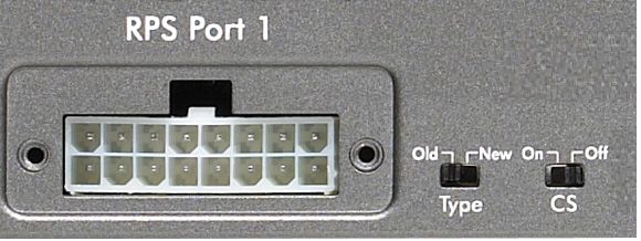
NETGEAR Managed Switch

No part of this publication may be reproduced, transmitted, transcribed, stored in a retrieval system, or translated into
any language in any form or by any means without the written permission of NETGEAR, Inc.
NETGEAR, the NETGEAR logo, and Connect with Innovation are trademarks and/or registered trademarks of
NETGEAR, Inc. and/or its subsidiaries in the United States and/or other countries. Information is subject to change
without notice. Other brand and product names are registered trademarks or trademarks of their respective holders. ©
2011 All rights reserved.

Technical Support
Thank you for choosing NETGEAR. To register your product, get the latest product updates, get support online, or for
more information about the topics covered in this manual, visit the support website at
http://support.netgear.com.
Phone (US & Canada only): 1-888-NETGEAR
Phone (Other Countries): Check the list of phone numbers at
http://support.netgear.com/app/answers/detail/a_id/984.Statement of Conditions.
To improve internal design, operational function, and/or reliability, NETGEAR reserves the right to make changes to the
products described in this document without notice. NETGEAR does not assume any liability that may occur due to the
use, or application of, the product(s) or circuit layout(s) described herein.

Revision History

Publication Part Number             Version             Publish Date                 Comments

202-11141-01                        v1.0                September 2012               First publication

                                                            2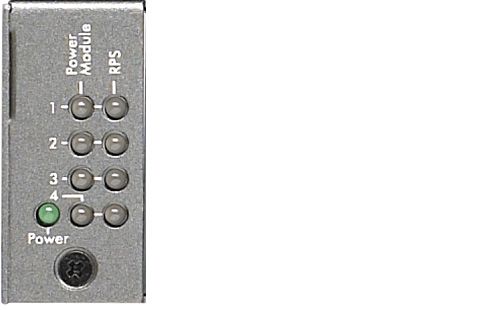
Contents

      Chapter 1          Introduction
           Front Panel and LEDs . . . . . . . . . . . . . . . . . . . . . . . . . . . . . . . . . . . . . . . . . 4
           Rear Panel . . . . . . . . . . . . . . . . . . . . . . . . . . . . . . . . . . . . . . . . . . . . . . . . . . 5
           Safety Instructions . . . . . . . . . . . . . . . . . . . . . . . . . . . . . . . . . . . . . . . . . . . . 5

      Chapter 2          Hardware Installation
           Package Contents . . . . . . . . . . . . . . . . . . . . . . . . . . . . . . . . . . . . . . . . . . . . 8
           Protect against Electrostatic Discharge . . . . . . . . . . . . . . . . . . . . . . . . . . . . 8
           Unpack the Hardware. . . . . . . . . . . . . . . . . . . . . . . . . . . . . . . . . . . . . . . . . . 9
           Installation . . . . . . . . . . . . . . . . . . . . . . . . . . . . . . . . . . . . . . . . . . . . . . . . . . 9
             Select a Location . . . . . . . . . . . . . . . . . . . . . . . . . . . . . . . . . . . . . . . . . . . 9
             Install the RPS . . . . . . . . . . . . . . . . . . . . . . . . . . . . . . . . . . . . . . . . . . . . 10
             Check the Installation . . . . . . . . . . . . . . . . . . . . . . . . . . . . . . . . . . . . . . . 11
             Connect to Power and Check the LEDs . . . . . . . . . . . . . . . . . . . . . . . . . 12
           Connect Equipment to the RPS4000 . . . . . . . . . . . . . . . . . . . . . . . . . . . . . 12
           RPS4000 Modes of Operation . . . . . . . . . . . . . . . . . . . . . . . . . . . . . . . . . . 13

      Chapter 3          Troubleshooting
           Troubleshooting Chart . . . . . . . . . . . . . . . . . . . . . . . . . . . . . . . . . . . . . . . . 20
           Additional Troubleshooting Suggestions . . . . . . . . . . . . . . . . . . . . . . . . . . 21

      Appendix A             Technical Specifications
           Specifications . . . . . . . . . . . . . . . . . . . . . . . . . . . . . . . . . . . . . . . . . . . . . . 22

      Appendix B             Notification of Compliance

                                                     3
1. Introduction
1
The NETGEAR Redundant Power System and Power Bank RPS4000 provides state-of-the-art,
high-performance, IEEE-compliant network solutions. This guide describes hardware installation
and basic troubleshooting for these managed switches.
The RPS can be freestanding or rack-mounted in a wiring closet or an equipment room. For
additional information, go to the NETGEAR website at http://www.netgear.com.
Front Panel and LEDs
The following figures show the front panel of the RPS4000. The front panel contains a set of
power module LEDs for each power module slot.
RPS status LEDs APS power module slots
Figure 1. RPS front panel
APS Power Module
status LEDs
RPS Power LED
Figure 2. RPS status LEDs
4NETGEAR Managed Switch
Table 1. LED descriptions
LED Description
Power Solid green: The RPS4000 power supply is operating normally.
Off: AC power to the RPS4000 is disconnected.
Power module (1–4) Solid green: An APS1000W is installed and working normally.
Solid yellow: An APS1000W is installed but has failed.
Off: No APS1000W is installed.
RPS (slots 1–4) Solid green: The RPS4000 detects a compatible switch. Power is provided.
Blinking green: The RPS4000 detects a compatible switch. No power is provided.
Solid yellow: The RPS4000 detects a switch of pre-RPS4000 design. Power is
provided.
Blinking yellow: The RPS4000 detects a switch of pre-RPS4000 design. No power
is provided.
Off: The RPS4000 does not detect a switch or the switch is not recognized.
Rear Panel
The RPS4000 rear panel has four RPS ports, four sets of Type and CS configuration
switches, and an AC power receptacle for the RPS4000 (AC power cord supplied).
RPS port RPS configuration switches AC power receptacle
Figure 3. RPS4000 rear panel
Safety Instructions
Use the following safety guidelines to ensure your own personal safety and to help protect
your system from potential damage.
To reduce the risk of bodily injury, electrical shock, fire, and damage to the equipment,
observe the following precautions.
• Observe and follow service markings:
- Do not service any product except as explained in your system documentation.
- Opening or removing covers that are marked with the triangular symbol with a
lightning bolt can expose you to electrical shock. Only a trained service technician
should service components inside these compartments.
Introduction
5NETGEAR Managed Switch
• If any of the following conditions occur, unplug the product from the electrical outlet and
replace the part or contact your trained service provider:
- The power cable, extension cable, or plug is damaged.
- An object has fallen into the product.
- The product has been exposed to water.
- The product has been dropped or damaged.
- The product does not operate correctly when you follow the operating instructions.
• Keep your system away from radiators and heat sources. Also, do not block cooling
vents.
• Do not spill food or liquids on your system components, and never operate the product in
a wet environment. If the system gets wet, see the appropriate section in your
troubleshooting guide or contact your trained service provider.
• Do not push any objects into the openings of your system. Doing so can cause fire or
electric shock by shorting out interior components.
• Use the product only with approved equipment.
• Allow the product to cool before removing covers or touching internal components.
• Operate the product only from the type of external power source indicated on the
electrical ratings label. If you are not sure of the type of power source required, consult
your service provider or local power company.
• To help avoid damaging your system, be sure that the voltage selection switch (if
provided) on the power supply is set to match the power available at your location:
- 115 volts (V), 60 hertz (Hz) in most of North and South America and some Far
Eastern countries such as South Korea and Taiwan
- 100 V, 50 Hz in eastern Japan and 100 V, 60 Hz in western Japan
- 230 V, 50 Hz in most of Europe, the Middle East, and the Far East
• Also, be sure that attached devices are electrically rated to operate with the power
available in your location.
• Use only approved power cables. If you have not been provided with a power cable for
your system or for any AC-powered option intended for your system, purchase a power
cable that is approved for use in your country. The power cable must be rated for the
product and for the voltage and current marked on the product’s electrical ratings label.
The voltage and current rating of the cable should be greater than the ratings marked on
the product.
• To help prevent electric shock, plug the system and peripheral power cables into properly
grounded electrical outlets.
• The peripheral power cables are equipped with three-prong plugs to help ensure proper
grounding. Do not use adapter plugs or remove the grounding prong from a cable. If you
must use an extension cable, use a three-wire cable with properly grounded plugs.
• Observe extension cable and power strip ratings. Make sure that the total ampere rating
of all products plugged into the extension cable or power strip does not exceed 80
percent of the ampere ratings limit for the extension cable or power strip.
Introduction
6NETGEAR Managed Switch
• To help protect your system from sudden, transient increases and decreases in electrical
power, use a surge suppressor, line conditioner, or uninterruptible power supply (UPS).
• Position system cables and power cables carefully; route cables so that they cannot be
stepped on or tripped over. Be sure that nothing rests on any cables.
• Do not modify power cables or plugs. Consult a licensed electrician or your power
company for site modifications.
• Always follow your local and national wiring rules.
Introduction
72. Hardware Installation
2
This chapter explains how to install the RPS.
Package Contents
The package contains the following items:
• RPS4000
• Power cord
• Rubber footpads for tabletop installation
• Rack-mounting kit
• Resource CD: The CD includes these documents or links to access them:
- RPS4000 Installation Guide
- This hardware installation guide
Protecting against Electrostatic Discharge
WARNING:
Static electricity can harm delicate components inside your
system. To prevent static damage, discharge static electricity
from your body before you touch any of the electronic
components, such as the microprocessor. You can do so by
periodically touching an unpainted metal surface on the switch.
You can also take the following steps to prevent damage from electrostatic discharge (ESD):
1. When unpacking a static-sensitive component from its shipping carton, leave it in the
antistatic package until you are ready to install it. Just before unwrapping the antistatic
package, discharge static electricity from your body.
2. Before moving a sensitive component, place it in an antistatic container or package.
3. Handle all sensitive components in a static-safe area. If possible, use antistatic floor pads,
workbench pads, and an antistatic grounding strap.
8NETGEAR Managed Switch
Unpack the Hardware
Check the contents of the box to make sure that all items are present before installing
the RPS:
1. Place the container on a clean flat surface and cut all straps securing the container.
2. Unpack the hardware from the box.
Carefully remove the hardware and place it on a secure and clean surface. See Select a
Location.
3. Remove all packing material.
4. Make sure that all items are present. See Package Contents.
Note: If any item is found missing or damaged, contact your local
NETGEAR reseller for replacement.
5. Inspect the products and accessories for damage. Report any damage immediately.
Installation
Install the equipment in the sequence presented in this section:
1. Select a location. See Select a Location.
2. Install the switch. See Install the RPS.
3. Check the installation. See Check the Installation.
4. Apply power and check the LEDs. See Connect to Power and Check the LEDs.
Select a Location
The RPS can be mounted in a standard 19-inch (48.26-centimeter) rack or left freestanding
(placed on a tabletop).
Hardware Installation
9NETGEAR Managed Switch
The site where you install the RPS can affect its performance. Before installing the switch or
switches, make sure that the chosen installation location meets the following site
requirements.
Table 1. Site requirements for RPS location
Requirements
Mounting Desktop installations: Provide a flat table or shelf surface.
Rack-mount installations: Use a 19-inch (48.3-centimeter) EIA standard
equipment rack that is grounded and physically secure. You need the
rack-mount kit supplied with the RPS.
Access Locate the RPS in a position that lets you access the front and rear connections
and view the front panel LEDs.
Power source Provide a power source within 6 feet (1.8 meters) of the installation location.
Power specifications for the RPS are shown in Appendix A. Be sure that a wall
switch does not control the AC outlet. A wall switch can accidentally turn off
power to the outlet and the RPS.
Environment Install the RPS in a site free from strong electromagnetic field generators (such
as motors), vibration, dust, and direct exposure to sunlight.
Temperature The ambient RPS operating temperature range is 0º to 50ºC (32º to 122ºF).
Keep the RPS away from heat sources such as direct sunlight, warm air
exhausts, hot-air vents, and heaters.
Operating humidity Install the RPS in a dry area with a maximum relative humidity of 90%,
noncondensing.
Ventilation Do not restrict airflow by covering or obstructing air inlets on the sides of the
RPS. Keep at least 2 inches (5.08 centimeters) free on all sides for cooling. Be
sure that there is adequate airflow in the room or wiring closet where you intend
to install the RPS.
Install the RPS
You can install the RPS on a flat surface or in a standard 19-inch rack.
Install the RPS on a Flat Surface
The RPS ships with four self-adhesive rubber footpads. Stick one rubber footpad on each
of the four concave spaces on the bottom of the RPS. The rubber footpads cushion the
RPS against shock and vibrations.
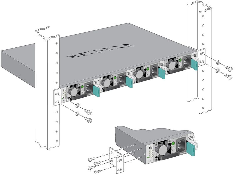
Install the Switch in a Rack
To install the RPS in a rack using the 19-inch rack-mount kit supplied with the RPS:
1. Attach the supplied mounting brackets to the side of the RPS.
Hardware Installation
10NETGEAR Managed Switch
2. Use the provided Phillips head screws to fasten the brackets to the sides of the
RPS.
Mounting
bracket
3. Tighten the screws with a No. 1 Phillips screwdriver to secure each bracket.
4. Align the bracket and rack holes. Use two pan-head screws with nylon washers to
fasten each bracket to the rack.
5. Tighten the screws with a No. 2 Phillips screwdriver to secure the switch in the rack.
6. Tighten the screws with a No. 2 Phillips screwdriver to secure the switch in the wall.
Check the Installation
Perform the following checks Before you apply power:
1. Inspect the equipment thoroughly.
2. Verify that all cables are installed correctly.
3. Check cable routing to ensure that cables are not damaged and do not create a safety
hazard.
4. Be sure that all equipment is mounted properly and securely.
Hardware Installation
11NETGEAR Managed Switch
Connect to Power and Check the LEDs
The RPS does not have an on/off switch. Apply or remove power by connecting or
disconnecting the RPS power cord. Before you connect the power cord, select an AC outlet
that is not controlled by a wall switch. A wall switch can turn off power to the RPS.
After you select an appropriate outlet, follow these steps to apply AC power:
1. Connect one end of the AC power adapter cable to the rear of the RPS, and the other
end to a grounded three-prong AC outlet.
2. Check the Power LED on the front panel of the RPS. The LED should light up in the
following sequence:
• The LED turns yellow as the RPS runs a power-on self-test (POST).
• If the RPS passes the test, the LED turns green. The RPS is working and ready to
pass data.
• If the POST fails, the Power LED blinks yellow.
If the Power LED does not light up, check that the power cable is plugged in correctly and
that the power source is good. For help with troubleshooting, see Chapter 3,
Troubleshooting.
Connect Equipment to the RPS4000
To connect a device to the RPS:
1. Disconnect the AC power cord on the switch or device.
2. Connect one end of the NETGEAR RPS cable to the RPS connector on the switch rear
panel.
3. Connect the other end of the NETGEAR RPS cable to the RPS4000 rear panel RPS port
connector.
4. Apply power to the RPS4000 by connecting the power cord to the RPS4000 power connect
in the front panel and to an AC powered outlet.
5. Apply power to the power module by connecting the power cord to the module power
connect in the front panel and to an AC powered outlet.
The RPS is working properly when all its front panel LEDs are lit as specified in Chapter 1,
LED Descriptions. If it is not, see Chapter 3, Troubleshooting.
WARNING:
Do not remove the RPS cable from the RPS or the powered device
when the connected device is on. First power the device off.
Second, remove the power cord from the power module. Remove
the device RPS power cable.
Hardware Installation
12NETGEAR Managed Switch
RPS4000 Modes of Operation
The RPS4000 rear panel has two slide switches for each of the four RPS ports. Each slide
switch has two positions, left and right. The slide switches control how the RPS4000 provides
power to the client switches.
RPS configuration switches
Type switch: In the Old (right position), the RPS is set to back up redundant power to a switch
of pre-RPS4000 design.
CS switch: Enables or disables current sharing.
Switch Description
Type Old: The RPS4000 is set to provide redundant power to a switch of pre-RPS4000
design.
New: The RPS4000 is set to provide redundant power to a switch of
RPS4000-compatible design.
CS (Current Share) On: Current sharing is enabled. The APS1000W for this module can be shared or
combined with other modules.
Off: Current sharing is disabled. The APS1000W for this module cannot be shared or
combined with other modules.
Note: For the operating modes described below, the setting of 'Type' and
'Current Share' must be identical for all four sets of slide switches.
Hardware Installation
13NETGEAR Managed Switch
Use the Type and CS slide switches to configure operating modes for the RPS4000. There
are six operating modes:
Legacy mode (Type=Old, CS=Off)
This mode supports old RPS (RPS5412) switches such as the GSM7328Sv1 where the RPS
port delivers power to switches as follows:
• System power (11 VDC): 150W maximum
• PoE power (56 VDC): 600W maximum
Note: RPS4000-provided PoE power replaces the switch's internal power
supply when the RPS4000 is connected to the switch, and the
power supply inside the switch becomes a standby power supply.
Applicable switches: GSM7328Sv2, GSM7352Sv2, GSM7328FS, GSM7228PS,
GSM7252PS, GSM7224v2, GSM7248v2, and M5300 series switches
Normal mode (Type=New, CS=Off)
This mode supports new switches such as the M5300 series that are compatible with the
RPS4000. The RPS port delivers power to the switch as follows:
• AC in = 100V–120V: Maximum power, 750W (system + PoE power)
• AC in = 200V–240V: Maximum power, 930W (system + PoE power)
Note: RPS4000 power replaces the switch’s internal power supply once
the RPS4000 is connected. The switch’s internal power supply
becomes a standby power supply.
Applicable Switches: M5300 series switches
High-power mode (Type=New, CS=On)
In this mode, each RPS4000 RPS port can output a maximum of 1440W of PoE power to a
device when two APS1000W power modules are present. APS1000W modules in slot 1 and
slot 2 work as a group to provide the combined power. Slot 3 and slot 4 can work as another
group. In this mode, only RPS port 1 and port 3 should be connected to the switch’s RPS
port. If port 2 and port 4 are also connected, they are ignored unless port 1 and port 3 are not
connected.
Note: This mode should be used only for new switches such as the
M5300-50G-POE+ that are compatible with the RPS4000 and
require high power (30W) for each of its 48 PoE ports.
Hardware Installation
14NETGEAR Managed Switch
• AC in = 100V~120V: Maximum power, 1500W (system + PoE power)
• AC in = 200V~240V: Maximum power, 1860W (system + PoE power)
Note: RPS4000 PoE power replaces the switch’s internal power supply to
become the main power supply, and the switch’s internal power
supply becomes a standby when the RPS4000 is connected to the
switch in this mode.
Applicable switches: M5300-52G-POE+ or compatible PoE switches
PoE power N+1 Mode (Type=New, CS=On
This mode should be used only for new switches like the M5300 series that are compatible
with the RPS4000. The Type and Current Share switch settings are same as high power
mode. The difference is the number of APS1000W modules that are present. In high-power
mode, two APS1000W modules are grouped together to provide the combined power. In PoE
power N+! mode, one APS1000W unit provides power to two switches that are in the same
group (slot 1 and slot 2 or slot 3 and slot 4). This mode is for switches that do not need all the
power one APS1000W can supply.
• AC in = 100V~120V: Maximum power 375W (System + PoE power) per switch/slot
• AC in = 200V~240V: Maximum power 465W (System + PoE power) per switch/slot
Note: Once connected, the RPS4000 PoE power replaces the switch
internal power supply. The switches power supply becomes a
standby power supply.
Applicable Switches: M5300-28G-POE+, M5300-52G-POE+
System Power N+1 Mode (Type=New, CS=Off)
This mode only provides 12v system power where one APS1000W is all is required to power
four switches. This mode is for non-PoE switches that do not need 48v PoE power.
The RPS4000 RPS port provides system power to devices as follows:
AC in = 100V~120V: Maximum power, 700W (system)
AC in = 200V~240V: Maximum power, 800W (system)
Note: Once connected, the RPS4000 PoE power replaces the switch’s
internal power supply. The switch’s power supply becomes a
standby power supply.
Applicable switches: All non-PoE switches that accept RPS support
Hardware Installation
15NETGEAR Managed Switch
Standby mode
The settings of the four sets of Type and Current Sharing switches are not the same. In this
mode, the RPS4000 delivers system power to a connected switch is as follows:
• System power (12V): maximum provided 200W.
• PoE power (56 VDC): Off.
Applicable switches: All non-PoE switches that accept RPS power.
Hardware Installation
163. Troubleshooting
3
Troubleshooting Chart
The following table lists symptoms, causes, and solutions of possible problems.
Table 1. Troubleshooting chart
Problem Cause Solution
Power LED is off. No power is received. Check the power cord connections for the switch
at the switch and the connected device.
Make sure that all cables used are correct and
comply with Ethernet specifications.
RPS port LED is off or Incorrect switch selections. Check the operating mode and CS switch
incorrect. selection.
17A. Technical Specifications
A
Table 1. Technical specifications
Feature Description
Environment Operating:
• Temperature: 32° to 122°F (0° to 50°C)
• Humidity: 90% maximum relative humidity, noncondensing
• Altitude: 10,000 ft (3,000 m) maximum
Storage:
• Temperature: – 4° to 158°F (–20° to 70°C)
• Humidity: 95% maximum relative humidity, noncondensing
• Altitude: 10,000 ft (3,000 m) maximum
Mean time between 168,208 hours (~19.2 years) @ 25°C
failure (MTBF) 55,879 hours (~6.4 years) @ 55° C
Electromagnetic CE mark, commercial, FCC Part 15 Class A, VCCI Class A, Class A EN 55022
emissions and immunity (CISPR 22) Class A, Class A C-Tick, EN 50082-1, EN 55024
Safety CE mark, commercial, CSA certified (CSA 22.2 #950), UL listed (UL 1950)/cUL
IEC950/EN60950
18B. Notification of Compliance
B
Certificate of the Manufacturer/Importer
It is hereby certified that the NETGEAR Redundant Power System and Power Bank RPS4000 have been suppressed
in accordance with the conditions set out in the BMPT-AmtsblVfg 243/1991 and Vfg 46/1992.The operation of some
equipment (for example, test transmitters) in accordance with the regulations may, however, be subject to certain
restrictions. Please refer to the notes in the operating instructions.
Federal Office for Telecommunications Approvals has been notified of the placing of this equipment on the market and
has been granted the right to test the series for compliance with the regulations.
Federal Communications Commission (FCC) Compliance Notice: Radio Frequency
Notice
This device complies with part 15 of the FCC Rules. Operation is subject to the following two conditions:
• This device may not cause harmful interference.
• This device must accept any interference received, including interference that may cause undesired operation.
Note: This equipment has been tested and found to comply with the limits for a Class A digital device, pursuant to part
15 of the FCC Rules. These limits are designed to provide reasonable protection against harmful interference in a
residential installation. This equipment generates, uses, and can radiate radio frequency energy and, if not installed
and used in accordance with the instructions, may cause harmful interference to radio communications. However,
there is no guarantee that interference will not occur in a particular installation. If this equipment does cause harmful
interference to radio or television reception, which can be determined by turning the equipment off and on, the user is
encouraged to try to correct the interference by one or more of the following measures:
• Reorient or relocate the receiving antenna.
• Increase the separation between the equipment and receiver.
• Connect the equipment into an outlet on a circuit different from that which the receiver is connected.
• Consult the dealer or an experienced radio/TV technician for help.
Canadian Department of Communications Radio Interference Regulations
This digital apparatus (NETGEAR Redundant Power System and Power Bank RPS4000) does not exceed the Class
A limits for radio-noise emissions from digital apparatus as set out in the Radio Interference Regulations of the
Canadian Department of Communications.
Règlement sur le brouillage radioélectrique du ministère des Communications
Cet appareil numérique (NETGEAR Redundant Power System and Power Bank RPS4000) respecte les limites de
bruits radioélectriques visant les appareils numériques de classe A prescrites dans le Règlement sur le brouillage
radioélectrique du ministère des Communications du Canada.
EN 55 022 Declaration of Conformance
This is to certify that the NETGEAR Redundant Power System and Power Bank RPS4000 are shielded against the
generation of radio interference in accordance with the application of Council Directive 89/336/EEC, Article 4a.
Conformity is declared by the application of EN 55024 Class A (CISPR 22).
19NETGEAR Managed Switch
EN 55 022 and EN 55 024 Statements
This is to certify that the NETGEAR Redundant Power System and Power Bank RPS4000 are shielded against the
generation of radio interference in accordance with the application of Council Directive 89/336/EEC, Article 4a.
Conformity is declared by the application of EN 55 022 Class A (CISPR 22) and EN 55 024.
WARNING!
This is a Class A product. In a domestic environment, this product
may cause radio interference, in which case the user may be
required to take appropriate measures.
Notification of Compliance
20You can also read