NEW DIGITAL ARCHITECTURE OF CNN FOR PATTERN RECOGNITION
←
→
Page content transcription
If your browser does not render page correctly, please read the page content below
Journal of ELECTRICAL ENGINEERING, VOL. 61, NO. 4, 2010, 222–228

                           NEW DIGITAL ARCHITECTURE OF
                           CNN FOR PATTERN RECOGNITION
                                                                                                                 ∗
                  Emil Raschman — Roman Záluský — Daniela Ďuračková

         The paper deals with the design of a new digital CNN (Cellular Neural Network) architecture for pattern recognition.
      The main parameters of the new design were the area consumption of the chip and the speed of calculation in one iteration.
      The CNN was designed as a digital synchronous circuit. The largest area of the chip belongs to the multiplication unit. In
      the new architecture we replaced the parallel multiplication unit by a simple AND gate performing serial multiplication.
      The natural property of this method of multiplication is rounding. We verified some basic properties of the proposed CNN
      such as edge detection, filling of the edges and noise removing. At the end we compared the designed network with other
      two CNNs. The new architecture allows to save till 86 % gates in comparison with CNN with parallel multipliers.
         K e y w o r d s: CNN, digital circuit, area consumption, pattern recognition

                  1 INTRODUCTION                                     basic properties of this type of neural network are the
                                                                     small chip area consumption, high speed and low power
   The need to process ever larger amounts of information            consumption.
requires a constantly increasingly computational com-                   The present VLSI circuits and technology allow to
plexity of circuits performing processing. This advance              manufacture chips with a very high density of integration,
in computational complexity can only be achieved by                  which makes possible hardware implementation with a
increasing the working frequency of the circuits which               high number of neurons (neural cells) on the chip. Nowa-
perform information processing or by using parallel pro-             days the biggest problem in hardware realization of neural
cessing. For real-time processing an enormous comput-                networks is the chip area consumption. The cells should
ing power is required that would cope with processing                occupy the smallest area on the chip. In digital design, the
of vast amounts of incoming information constantly. One              largest area is occupied by the multiplier and the adder,
of the solutions of real-time applications uses neural net-          hence we need to propose an alternative way of multi-
works. The neural networks achieve an enormous com-                  plication and addition in order to lower the chip area
puting power basically thanks to parallel processing per-            consumption.
formed by a large number of simultaneously working el-                  We designed a new architecture of the digital neural
ementary processors, the so-called cells. The next advan-            network with multiplication signals decomposed in time
tage of some neural networks is their ability to learn due           by means of an AND gate. The hardware multiplication
to which we need not develop complex software for pro-               was replaced by the AND gate and a counter. The counter
cessing the data that occupy a lot of place in the memory.           summarizes the output of the AND gate and transforms
The system for data processing performs simple learning              this output to a 5 bit number. The circuits also contain a
with a special training aggregate.                                   Converter block which performs distribution of the signal
   For image and pattern processing most frequently we               in time before multiplication by the AND gate. The natu-
use the so-called cellular neural networks marked as CNN.            ral property of our multiplication is rounding. The design
This type of networks contains a lot of cells (computing             of the new architecture brought saving of 86.8 % of gates
elements) that are interconnected analogically as the neu-           in comparison with a standard CNN with parallel signal
rons in the human brain. An analogue architecture of this            multipliers.
network was proposed by L.O. Chua a L. Yang [1, 2]. CNN
are used for image processing and pattern recognition.
   A CNN can be realized by means of analog or digi-                     2 THE BASIC PRINCIPLE OF THE CNN
tal circuits. Various hardware implementations are pre-
sented in the literature [9–12]. The advantage of analog                 Cellular neural networks are best for applications fo-
implementation is a smaller chip area and the advantage              cused on pattern recognition. The advantage of the CNN
of digital implementation is easy modification for weight            is its simple architecture. The basic principles of the CNN
coefficients in the process of learning. In our work we              are explained in [3–6]. The cellular neural network is usu-
focus on a digital neural network. Its advantage is a rel-           ally a non-linear cellular network. This is a group of spa-
atively easy implementation in the FPGA circuits. The                tially distributed cells, where every cell is a neighbour to

 ∗ Slovak University of Technology, Department of Microelectronics, Ilkovičova 3, 812 19 Bratislava, Slovakia, emil.raschman@stuba.sk

                                                  ISSN 1335-3632 c 2010 FEI STU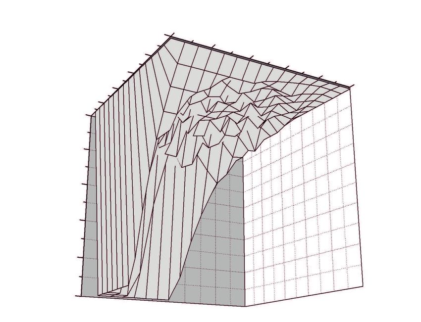
Journal of ELECTRICAL ENGINEERING 61, NO. 4, 2010                                                                        223

Fig. 1. CNN with size M × N and marked cell Cij and its r -                Fig. 2. Graphical representation of the CNN cell
                     neighbourhood = 1

                                                                       The control input of the CNN is a weight matrix,
                                                                    where each coefficient represents some weight (impor-
                                                                    tance) of the corresponding input. Then each input is
                                                                    multiplied by a certain weight constant. By summarizing
                                                                    this conjunction we get the function Net .

Fig. 3. Transfer functions ( θ define boundary, when neuron stake
                                                                               Net = w1 s1 + w2 s2 + · · · + wm sm .          (1)
                             is active)
                                                                    In this equation, coefficients w represent the weights and
                                                                    coefficients s represent the incoming signals from the
                                                                    surrounding cells. The output of cell y we get from a
                                                                    non-linear transform of Net :

                                                                                           Y = f (Net) .                      (2)

                                                                    Function f ( ) is called the transfer or activation function.
                                                                    This function designates the output state of the cell. The
                                                                    block diagram of the cell of the CNN is in Fig. 2.
                                                                        There exist several transfer functions [7, 8] as for ex-
                                                                    ample a sigmoid function, hard-limiter or threshold logic
                                                                    utilized in a few applications. Our CNN has a hard-limiter
                                                                    and a threshold logic function (Fig. 3). Parameter θ rep-
                                                                    resents the boundary, when the neuron is in an active
                                                                    mode. For our network, parameter θ for the hard-limiter
                                                                    function is zero and for the threshold logic parameter θ
                                                                    is from the range h−1, 1i, and α = 1 . The choice of the
                                                                    transfer function depends on the application of the neural
                                                                    network.
                                                                        By a proper choice of the weight matrix we can achieve
                                                                    that the CNN is able, for example, to remove noise. By
   Fig. 4. Weights in the proposed 15 s system of the timing        choosing the matrix we set input conditions for input data
                                                                    processing by CNN.

                                                                        3 THE NEW DESIGN OF DIGITAL CNN

                                                                       The basic principle of the CNN is very similar to that
Fig. 5. An example of the evaluation for weight wgt = 6/15 and      of a biological neuron. The network consists of a number
                       input x = 11/15                              of basic computing elements, the so-called cells. The in-
                                                                    coming inputs of the cells are multiplied by corresponding
                                                                    weight coefficients, then the results of multiplication are
itself and is locally connected with the neighbouring cells         summarized and in the end the sum is conversed through
in some extent of action referred to as r -neighbourhood            the transfer function. Since all cells realize data process-
(Fig. 1).                                                           ing by parallel calculation, the computing power of the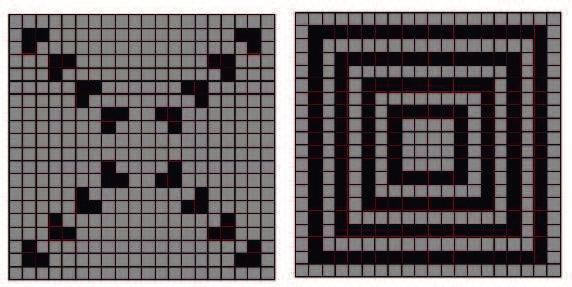
224     E. Raschman — R. Záluský — D. Ďuračková: NEW DIGITAL ARCHITECTURE OF CNN FOR PATTERN RECOGNITION

                               Fig. 6. Decomposition errors depending on the factor conjunction

                                                                3.1 Multiplication of the signal using the AND
                                                                    gate

                                                                   As an alternative possibility of multiplication we de-
                                                                signed a circuit that multiplies the input values and
                                                                weight coefficients by means of AND gate. The method of
                                                                multiplication is based on the fact that by multiplication
                                                                the input value must be converted to the time interval
                                                                from the beginning of the time-window and the weight
                                                                value has to be specially picked so that multiplication
                                                                takes place when the input and weight signals pass the
            Fig. 7. Block diagram cell of the CNN               gate. We proposed a special coding for the weights.
                                                                   We used a special system of 15 parts, ie one cycle
                                                                of multiplication is divided into 15 parts (time-window).
                                                                In such a time period it is possible to code 16 various
                                                                values of weight or inputs. Decomposition signals for cor-
                                                                responding weight values are displayed in Fig. 4.
                                                                   As an example we have an input value of x = 8/15
                                                                that we multiply by a weight of w = 5/15 according
                                                                to Fig. 5. The input values must be converted to the
                                                                time interval from the beginning of time axis, its length
                                                                corresponding to the input size. The result at the end of
                                                                the time window will be y = 3/15 . The real value of the
                                                                multiplication xw = 0.18 and our result of multiplication,
                                                                as shown in Fig. 5, is 3/15 = 0.2 .
                                                                   The natural property of the proposed method of mul-
                                                                tiplication is rounding. For verifying the effect of round-
                                                                ing on the result of the CNN we created a simulator as
                                                                macro in Visual Basic for Application in Microsoft Excel.
                                                                We used the simulator to recognize that we can neglect
                                                                this rounding. For example the effect of multiple round-
                                                                ing upon intermediate result causes that the final result
        Fig. 8. Connections between the cells of CNN            of network is delayed by about one iteration than without
                                                                rounding.
CNN is directly proportional to the number of cells. The           The value of the error of computing depends on the
more cells contained in the network, the more information       factors of conjunction. Decomposition error is shown in
achieve synchronized processing. Therefore in the design        Fig. 6. Picture a) is the decomposition absolute error. Its
of the CNN our effort is focused on minimizing the cell         maximum value is 0.031 . Decomposition of the absolute
size, thereby providing a maximum number of cells on the        error is relatively constantly within the full range. Pic-
chip. The size of the chip is one of the biggest problems in    ture b) is the absolute error in percentage. In the figure
the design of CNNs. The largest area is reserved for the        we can see the effect of the rounding, where for very small
multiplexer, so we looked for alternative multiplications.      numbers that were rounding to zero the absolute error is
Journal of ELECTRICAL ENGINEERING 61, NO. 4, 2010                                                                     225

                                                                  The choice of the transfer function depends on the appli-
                                                                  cation of the neural network. For edge detection, filling
                                                                  of the edges the hard-limiter function is better, and for
                                                                  noise removing the threshold logic function is better.
                                                                     The converted signal is coming through the multi-
                                                                  plexer mx to the block converter . The multiplexer mx
                                                                  allows entering new input values to the network. Block
                                                                  converter has two functions: it contains a register, where
                                                                  the result is saved, from where it can be read (data out ),
                                                                  and a circuit converting result to the time interval corre-
                                                                  sponding with size of results (statex o, sign o), which is
                                                                  fed to the surrounding cells.

                                                                  3.3 A novel architecture of the CNN

                                                                     The CNN consists of a field of cells, each cell being
                Fig. 9. Block diagram of CNN
                                                                  coupled with all the nearest neighbours, thus the output
                                                                  of the cell is the input to all surrounding cells. These
                                                                  coupled cells in the CNN are displayed in Fig. 8. In this
                                                                  picture we can see that every cell is on the fifth input
                                                                  coupled with its own output because in the CNN theory
                                                                  every cell is a neighbour to itself too. The boundary cells
                                                                  contain inputs which are not coupled with the surround-
                                                                  ing cells because there do not exist neighbouring cells.
                                                                  These inputs are connected to log. “0”.
                                                                     The general design of the CNN is in Fig. 9. The com-
                                                                  plete network contains a network of coupled cells, weight
                                                                  and sign registers and a control circuit. The weights and
                                                                  their signs from registers are fed to each cell. The control
Fig. 10. Block diagram of one cell of the CNN presented at [13]   circuit performs synchronization of the whole circuit.

                                                                              4 THE COMPARISION OF
100 %. Nevertheless, these number are so small that we                        OUR CNN WITH OTHERS
can ignore them. A proper selection of the weight coef-
ficients allows to shift the calculation in the areas with           The CNNs new architectures were compared with
minimum errors because for the weight matrix the ratio            other digital CNNs. For comparison we selected the fol-
of coefficients is more important than their values.              lowing networks:
                                                                   • Our previous CNN [13].
3.2 The cell of proposed CNN                                       • “Standard” digital CNN with parallel signed multipli-
                                                                     ers.
   The proposed circuit is a digital synchronous circuit.         All networks compared were designed for processing 5-bit
The designed circuit has been realized by means of the            data, where 4 bits represented the values and highest bit
descriptive language VHDL in Xilinx. The cell contains            represented sign of values.
several sub-circuits. The block diagram of the cell is in
Fig. 7. On the inputs of the cell there are 9 weight and 9
                                                                  1 Our previous CNN
input signals and their corresponding signs. Eight input
signals are connected to the outputs of the neighboring               This network was previous to our new CNN architec-
cells, and one input, the fifth in sequence, is connected         ture. The network was proposed as a synchronous digital
to its own output of the cell because in the CNN the-             circuit utilizing multiplication of signals by decomposi-
ory the cell is a neighbour to itself. Then the inputs are        tion in time by means of a logical AND gate. The main
multiplied with weights in the logical AND gate and the           difference against the new architecture is a low speed and
sign of inputs are compared with the logical XOR gate.            circuit complexity. The block diagram of one cell of this
The weight must be specially distributed in time, so that         network is shown in Fig. 10. Every cell contains a weight
by passing through the AND gate the signals are multi-            register which consists of weg reg storing the value of the
plied. After multiplication by the AND gate the results           weight and sign reg containing information about the sign
are counting in the counter and consequentially converted         of the weight. On the input there are two multiplexers
by the transfer function. Our CNN has two transfer func-          that are multiplexing the inputs (incoming from the sur-
tions: hard-limiter and threshold logic function (Fig. 3).        rounding cells) and their sign. The output of the weight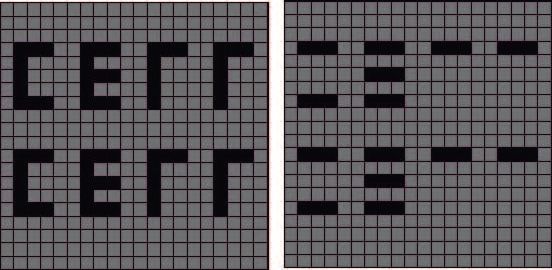
226 E. Raschman — R. Záluský — D. Ďuračková: NEW DIGITAL ARCHITECTURE OF CNN FOR PATTERN RECOGNITION
plication are added in the block counter . The output of
the counter is converted by the threshold logic function
in block transfer function and thereafter converted to the
time interval corresponding to the values of the output in
the block converter .
Multiplication of inputs with weights is realized se-
quentially. In the first step the inputs of all cells are mul-
tiplied with the first weight and the result is saved in
the counter . The next step inputs are multiplied with
the second weight and the result is saved in the counter ,
etc. Calculation of one iteration step of the network takes
Fig. 11. Block diagram of one cell of “standard” CNN containing 9 × 15 , thus 135 clock cycles.
parallel signed multipliers
2 “Standard” digital CNN with parallel signed
multipliers
This network was designed by means of standard par-
allel signed multipliers. The block diagram of one cell of
this network is in Fig. 11. Block parallel signed multi-
plier contains 9 signed multipliers which simultaneously
multiply all weights with appropriate inputs. This block
contains 9 outputs corresponding to 9 results of multipli-
cation. These results are summarized in the adder and
subsequently converted by the transfer function realized
by the threshold logic or hard limiter function.
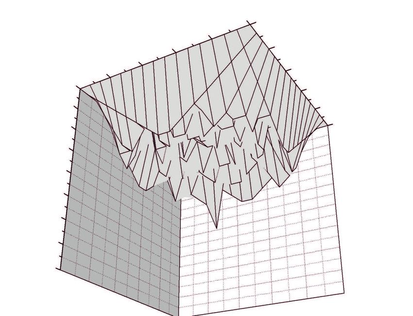
Fig. 12. Detection of horizontal edges
5 RESULTS
For verification of the properties and behaviour of the
proposed neural network we need a sufficient number of
cells. The proposed network is of fully cascade type, ie
we can create the network with an optional number of
cells. In our experiments we used application for 400 cells.
Then the input of the neural network is an input matrix
of 20 × 20 in size and the weight matrix has a size of
3 × 3 . During testing the networks we focused mainly on
the properties of the network such as the edge detection,
fill-up of missing edges and noise removing. The results
Fig. 13. Completion of missing edges
of simulation are in Figs. 12–14. During these simulations
we applied a hard-limiter transfer function. For better in-
terpretation we displayed the input to output matrix also
register is multiplication with the output of the multi- in a graphical form. Each cell can have 31 different val-
plexer in mux in a logical AND gate and their signs are ues, which are represented by 31 shades of gray. First we
compared in a logical XOR gate. The results of multi- verified the network facilities by detection of horizontal
Fig. 14. Noise removal, a) Input, b) Output after the use of an inappropriate weight matrix, c) Perfect noise removalJournal of ELECTRICAL ENGINEERING 61, NO. 4, 2010 227
Table 1. Comparison of parameters for CNN cell
Parameters
Cell of the Speed of Max. Time of
CNN one Bells Flip Flops Total frequency calculation of
iteration one iteration
CNN with 5bit 4 CLK
signed parallel cycles 1207 208 1415 86 MHz 46.5 ns
multipliers
Our previous 135 CLK 272 189 461 330 MHz 409 ns
CNN cycles
New design 15 CLK 155 32 187 369 MHz 40.65 ns
of the CNN cycles
is a comparison the designed network with other neural
networks. Our new designed network we compared with
network, which are presented in [13] and with standard
network containing 5-bits parallel signed multipliers.
Designed circuit was realized by means of descrip-
tion language VHDL in development environment Xil-
inx. After synthesis of CNN for FPGA “Xilinx Virtex 5
XC5VFX30T” we were given results, which are shown in
the “Table 1”. The main request of our design has been
to propose CNN, which could occupy the minimum of the
chip area. Parameters representing the size of one cell are
divided in the three columns Bels (Lut, mux, xor, inv, . . .
), Flip Flops (flip flops) and Total (total number of gates).
The network with parallel multipliers has the biggest area
consumption. One cell in the standard network with par-
Fig. 15. Comparison of the CNNs allel multipliers is created by 1415 of gates. Our previous
design contains 461 of gates, which is 3 times less than
in the standard network. The new architecture networks
edges. As an input we used a pattern with two words has the smallest area consumption. The cells of our new
“CELL” containing 14 horizontal edges. In Fig. 12 one design network have only 187 gates, which is 7.5 times
can see that the required output is achieved already after less than in the standard network.
the second iteration. Further we verified the network fa- The second parameter was the speed of the circuit.
cilities for filling-up the missing edges (Fig. 13). As inputs The standard network with parallel multipliers needed
to the network we used the corners. For connecting these the smallest number of clock signals to calculate one it-
corners to the network we needed 7 iterations. Finally we eration (4 clock cycles), though its maximal frequency
tested the network facilities as the noise removing from is only 86 MHz. The time of calculation of one iteration
picture (Fig. 14). The input was the number “35” with is 46.5 ns. The quickest was the network with the new
noise of approx. 30 %. In this figure, output 1 is the result architecture, which needed 15 clock cycles but its maxi-
of incorrectly choosing the weight matrix and output 2 is mal frequency is 369 MHz, thus the time for one iteration
the result after properly choosing the weight matrix. In is 40.65 ns. The slowest was our previous model, which
this case, noise was 100 % filtered. needed 409 ns for one iteration.
From the presented examples it is possible to conclude The cell of the new network has 7.5 times less gates than
that the network satisfies the set requirements. The speed the standard network with parallel multipliers (which is
and correctness of the output depends on properly choos- reduction by 86.8 % of gates) and its speed is little higher
ing the transfer function and weight matrix. The weight (calculation of one iteration is about 5.85 ns shorter). Due
matrix was defined intuitively — “trial-and-error”. In the to parallel calculations of all cells the speed of the network
future we would like to set the weight matrix by learning with an optional number of cells is given as the speed of
the network. one cell calculation. Duration of one iteration is 15 clock
The main aim of our work was to propose a new ar- cycles. This speed of network is sufficient. In Fig. 15 there
chitecture of the CNN with an alternative way of multi- is a dependence of the consumption of gates versus the
plication that allows to reduce the chip area. The main number of cells. With an increasing number of cells, also
parameters compared were the speed and area consump- the difference between the number of gates of each CNN
tion (number of gates) of the network. In Table 1 there increases.228 E. Raschman — R. Záluský — D. Ďuračková: NEW DIGITAL ARCHITECTURE OF CNN FOR PATTERN RECOGNITION
6 CONCLUSION [7] KVASNIČKA, V.—BEŇUŠKOVÁ, L’—POSPÍCHAL, J.—FAR-
KAŠ, I.—TIŇO, P.—KRÁL’, A. : Introduction to Theory of
We designed a new architecture of the digital neural Neural Network, IRIS, 1997. (in Slovak)
network, with multiplication signals decomposed in time [8] JEON, J. : Fuzzy and Neural Network Models for Analyses of
Piles, A dissertation submitted to the Graduate Faculty of North
by means of an AND gate. The natural property of our Carolina State University, Raleigh, North Carolina, Aug 2007.
multiplication is rounding. The values of the input and [9] RESTREPO, H. F.—HOFFMAN, R.—PEREZ-URIBE, A.—
output from the cell can be obtained by values from −1 TEUSCHER, C.—SANCHEZ, E. : A Networked FPGA-Based
to 1 with a step of 1/15 , which presented 31 shade of Hardware Implementation of a Neural Network Application,
gray. We verified some basic properties of the proposed In (K.L. Pocek and J.M. Arnold Proceedings of the IEEE
CNN such as edge detection, filling of the edges and noise Symposium on Field Programmable Custom Computing Ma-
chines, FCCM’00, eds.), pp. 337–338, Napa, California, USA,
removing. Apr 17–19, 2000. IEEE Computer Society, Los Alamitos, CA.
In comparison with the standard CNN with parallel [10] MUTHURAMALINGAM, A.—HIMAVATHI, S.—SRINIVA-
multipliers, our designed network is 4 times slower but SAN, E. : Neural Network Implementation Using FPGA: Issues
allows to save up to 86 % of gates and thereby allows and Application, International Journal of Information Technol-
ogy 4 No. 2 (2008).
to create a network with identical parameters with a
[11] BOUBAKER, M.—KHALIFA, K. B.—GIRAU, B.—DOGUI,
fundamentally large number of cells. In Fig. 15 we see
M.—BEDOUI, M. H. : On-Line Arithmetic Based Repro-
that our new CNN needs a lower number of gates for a grammable Hardware Implementation of LVQ Neural Network
given amount of cells than other compared networks. for Alertness Classification, IJCSNS International Journal of
In the future we would like to create a network im- Computer Science and Network Security 8 No. 3 (Mar 2008).
plementation in to FPGA chip and connect it with a [12] LARKIN, D.—KINANE, A.—MURESAN, V.—O’CONNOR,
N. : An Efficient Hardware Architecture for a Neural Network
PC, which requires creating a communication and user
Activation Function Generator, Lecture Notes in Computer Sci-
interface and defining an input weight matrix based on ence, 2006.
learning networks by means of an incoming learning set [13] RASCHMAN, E.—ĎURAČKOVÁ, D. : The Novel Digital De-
of data. sign of a Cell for Cellular Neural Network, Proceedings of the
Electronic Devices and Systems, Brno, Sep 2008, pp. 322–325.
Acknowledgment
Received 4 December 2009
This contribution was supported by the Ministry of
Education of the Slovak Republic under grant VEGA Emil Raschman received the MS degree in Electronics
No 1/0693/08 and conducted in the Centre of Excellence from Slovak University of Technology in Bratislava, Slovakia,
CENAMOST (Slovak Research and Development Agency in 2007. Since September 2007 he has been PhD student at
Contract No. VVCE-0049-07). Microelectronics Department of Slovak University of Technol-
ogy. He is the author or co-author of more than 10 papers
presented at international conferences. His main research in-
References terests are Digital design and neural networks.
Roman Záluský received the MS degree in Electronics
[1] CHUA, L. O.—YANG, L. : Cellular Neural Network: Theory, from Slovak University of Technology in Bratislava, Slovakia,
IEEE Trans. Circuits Systems 35 (Oct 1988), 1257–1272. in 2008. Since September 2008 he has been PhD student at
[2] CHUA, L. O.—YANG, L. : Cellular Neural Network: Aplica- Microelectronics Department of Slovak University of Technol-
tions, IEEE Trans. Circuits Systems 35 (Oct 1988), 1273–1290. ogy. He is the author or co-author of more than 10 papers
[3] HNGGI, M—MOSCHYTZ, G. S. : Cellular Neural Network: presented at international conferences. His main research in-
Analysis, Design and Optimalization, Kluwer Academic Pub- terests are Digital design and neural networks.
lisher, Boston, 2000.
Daniela Ďuračková (Prof, Ing, CSc), received her MSc
[4] SORDO, M. : Introduction to Neural Networks in Healthcare,
Open Clinical Knowledge Management for Medical Care, Oct
and CSc (PhD) from the Faculty of Electrical Engineering
2002. and Information Technology, Slovak University of Technology
[5] LARSEN, J. : Introduction to Artifical Neural Network, 1 st
in 1974 and 1981 respectively. Since 1991 she has been an
Edition, Section for Digital Signal Processing Department of associate Professor at the Microelectronics Department of the
Mathematical Modeling Technical University of Denmark, Nov Faculty of Electrical Engineering and Information Technology,
1999. Slovak University of Technology in Bratislava. The main field
[6] SEUNG, S. : Introduction to Neural Networks: Lecture 1, The of her research and teaching activities has moved from semi-
Massachusetts Institute of Technology — The Seung Lab, Sep conductor devices towards the design of analog and digital
2002. ASICs and neural network implementation on-chip.You can also read