NEW ERASMUSRAND PEDESTRIAN BRIDGE OVER N1 INPRETORIA UPGRADING OF THE RIMER'S CREEK WATER TREATMENT WORKS - SAICE
←
→
Page content transcription
If your browser does not render page correctly, please read the page content below
March 2020      Vol 28 No 2

                                    Sivili Enjeneereng

NEW ERASMUSRAND UPGRADING OF THE      SAISC 2019
PEDESTRIAN BRIDGE RIMER’S CREEK WATER STEEL AWARDS
OVER N1 IN PRETORIA TREATMENT WORKS   ALL THE WINNERS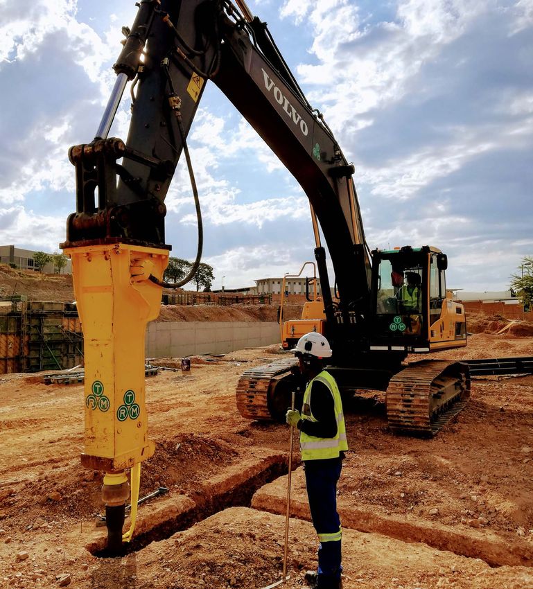
FR O M T H E PR E S I D E N T ’ S D E S K
Ethical leadership
Ethics is topical in our economy and body main road connecting it to other sur- with other individuals or households
politic, primarily because of the challenges rounding villages and centres of economic there must be a mechanism that makes
the country is currently facing – corruption, activity. The development is so remarkable it possible and desirable for them to
growing inequality, high unemployment that people are now building themselves cooperate – i.e. the benefits of cooperation
rate, blurred lines on conflict of interest, double-storey houses on stands of 2 000 must outweigh those of working in isola-
construction mafias, nepotism, procure- to 3 000 m2, which is leading to questions tion, and similarly the costs of working
ment rules not followed, late awarding of of whether the classification of a village is in cooperation with others must be lower
contracts, patronage networks, not fin- still appropriate. The place is now looking than those of working alone. This is where
ishing projects, appointing inexperienced more and more like a township. Similarly, bold and decisive leadership is required to
contractors, cutting maintenance budgets, the surrounding areas that were regarded take the country on an inclusive growth
and so on. These are threatening to undo as villages are transitioning to townships. trajectory in an ever-changing global
the great achievements of the democratic The same can be said of areas around environment. One acknowledges that, in
dispensation. In this respect the following Nandoni Dam in Venda, where villages the process of seeking solutions, various
three problem areas have a ripple effect: are being turned into ‘Golf Estates’. This is stakeholders’ interests should be addressed
good, because some people now no longer and catered for.
Procurement see the need to migrate to urban areas in
My submission is that our country has search of jobs. Shopping centres are built IN CONCLUSION
good laws, policies and regulations, and if in these areas and have become a source The Thuma Mina spirit (“send me”), albeit
we follow them by the book, many of these of local employment. Our government with a reduced momentum, is a great
problems would not exist. Conducting should be commended for the sterling initiative which should be supported by
procurement of goods and services from work they have done in providing some of every South African who desires economic
suppliers should not be as difficult as the basic services to these communities. growth levels above 3%. As the National
landing on the moon or performing heart Of course one acknowledges that more Development Plan aspires to achieve eco-
surgery. The seven cardinal sins (greed, work is still required. nomic growth levels of more than 5%, we
gluttony, pride, envy, lust, wrath and sloth) This brings me to the question of should raise our hands now, as we cannot
are holding back the country’s development stealing from the poor. The above develop- wait until we get there.
and negatively impacting on the opportu- ments are great and must be commended
nity to be considered one of the respectable as indicated; however, the quality of the Fana Marutla
nations of the world. In particular greed new infrastructure (especially roads)
(intense and selfish desire for wealth, is very poor. The new roads are built SAICE President 2020
fmarutla@gibb.co.za
power, fame, etc, at the expense of others) by inexperienced contractors who are
has been seen to normalise wrongdoing “politically connected”, resulting in poor
with no consequences to the wrongdoers. quality roads that are not fully achieving
This malfeasance is destroying our today the ultimate goal of encouraging economic
and stealing our tomorrow. One can activity in these areas. Hence the full value
only envy the development that is taking for money is not realised, as repair main-
place in countries like China, where the tenance on these roads has to start earlier
development of economic infrastructure is than expected.
a top priority.
Decisive leadership
Corruption robs the poor the most In his book “The Architects of Poverty”,
The village where I grew up in Limpopo Moeletsi Mbeki reminds us that countries
(Thabampshe, Ga-Masemola) has seen develop primarily by pooling the collective
a great change in the last 26 years. In strengths and energies of their citizens to
1994, when we voted for the first time, achieve a common goal. For this to happen
the village did not have electricity (yes I two key elements must be present –
mean 0% coverage), no tarred roads and institutions that facilitate cooperation, and
a severe water shortage. I wrote matric leaders who ensure that these institutions
in 1991 using paraffin and candle lights. function and deliver on expectations. If
Fast-forward to 2020 – every household individuals or households are expected
has electricity and the village has a tarred to pool their energies and resources
Civil Engineering March 2020 1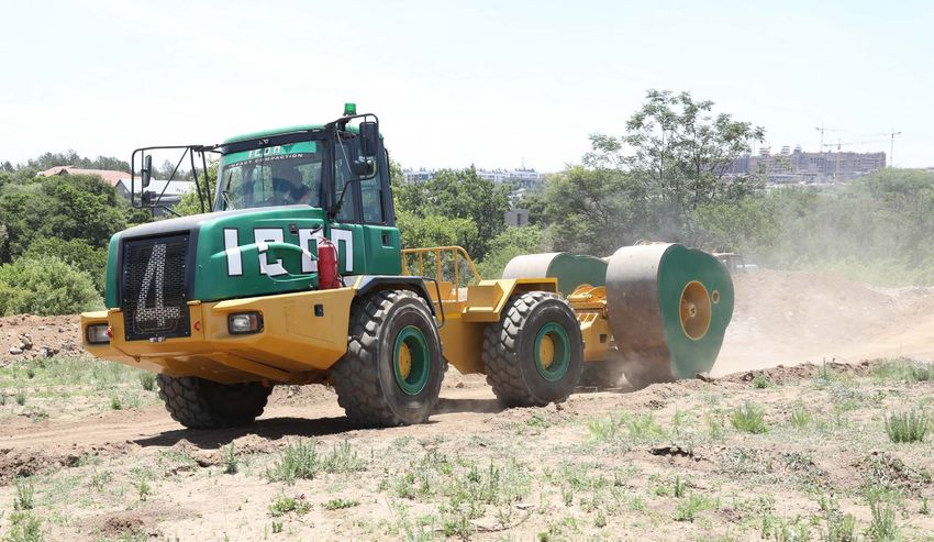
March 2020 Vol 28 No 2
Sivili Enjeneereng
NEW ERASMUSRAND UPGRADING OF THE SAISC 2019
PEDESTRIAN BRIDGE RIMER’S CREEK WATER STEEL AWARDS
OVER N1 IN PRETORIA TREATMENT WORKS ALL THE WINNERS
On the Cover P4
Sivili Enjeneereng = Setswana
ON THE COVER
TRM Piling (Pty) Ltd has a well-established
track record for deep foundations
engineering applications and solutions Since its introduction to the African market almost a decade ago, the TRM piling system has been
throughout southern Africa, having designed selected and successfully used at numerous challenging projects across South Africa and the continent
and installed TRM piled foundations for
various structures, including transmission
lines, bridges, silos, conveyors, screening
plants, tanks, heritage sites, mines, car FROM THE PRESIDENT’S DESK
dealerships, office buildings, apartment
blocks, retrofits and power plants. Ethical leadership ��������������������������������������������������������������������������������������������������������������������������������������������������������������������������������������������������������������������������������������������������������������������������������� 1
South African
Institution of
Civil Engineering
ON THE COVER
March 2020 Vol 28 No 2
TRM Piling – designed and installed ���������������������������������������������������������������������������������������������������������������������������������������������������������������������������������������������������������������������� 4
Sivili Enjiniereng
Published by SAICE
STRUCTURAL ENGINEERING
Block 19, Thornhill Office Park,
Bekker Street, Vorna Valley, Midrand
Private Bag X200, Halfway House, 1685 Interaction between the bridge and geotechnical engineer –
Tel +27 11 805 5947/8 | Fax +27 11 805 5971
http://www.saice.org.za | civilinfo@saice.org.za finite element modelling of rock foundations������������������������������������������������������������������������������������������������������������������������������������������������������������������������������������������ 8
Wind farm projects flying��������������������������������������������������������������������������������������������������������������������������������������������������������������������������������������������������������������������������������������������������� 15
Acting Chief Executive Officer
Steven Kaplan Pr Eng
steven@saice.org.za | Tel +27 11 805 5947/8
Editor
Verelene de Koker Upgrading of the Rimer’s Creek Water Treatment Works��������������������������������������������������������������������������������������������������������������������������������������������������� 20
verelene@saice.org.za
Tel +27 11 805 5947/8 | Cell +27 83 378 3996
Design and construction of the Erasmusrand Pedestrian Bridge ��������������������������������������������������������������������������������������������������������������������������� 22
Editorial Panel
The fire safety performance of internal and external walls in multi-storey buildings����������������������������������������������������������� 28
Marco van Dijk (chairman), Irvin Luker (vice‑chairman),
Fana Marutla (president), Steven Kaplan (acting CEO),
Andile Gqaji, Jeffrey Mahachi, Avi Menon,
Prisca Mhlongo, Jones Moloisane, Beate Scharfetter,
Verelene de Koker (editor), Sharon Mugeri
(editor’s assistant), Barbara Spence (advertising) Steel Awards – showcase of continued excellence����������������������������������������������������������������������������������������������������������������������������������������������������������� 32
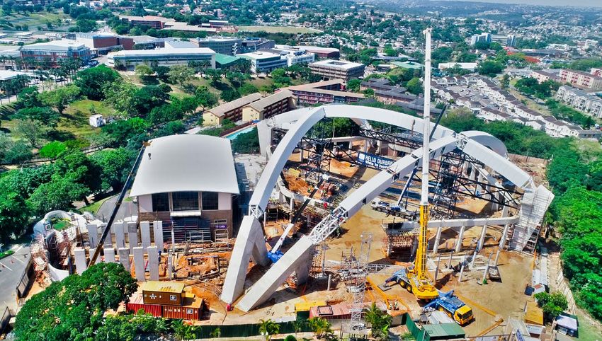
Durban Christian Centre Roof Structure������������������������������������������������������������������������������������������������������������������������������������������������������������������������������������������������������� 32
Annual subscription rate
R730.00 (VAT included)
Protea Glen Secondary School 2��������������������������������������������������������������������������������������������������������������������������������������������������������������������������������������������������������������������������� 35
Advertising
Barbara Spence, Avenue Advertising
barbara@avenue.co.za
Tel +27 11 463 7940 | Cell +27 82 881 3454
Design and reproduction Peech Hotel������������������������������������������������������������������������������������������������������������������������������������������������������������������������������������������������������������������������������������������������������������������������������������� 36
Marketing Support Services, Ashlea Gardens, Pretoria
Printing
Fishwicks, Pretoria
Omnia Nitrophosphate Plant ������������������������������������������������������������������������������������������������������������������������������������������������������������������������������������������������������������������������������������ 37
The 1054��������������������������������������������������������������������������������������������������������������������������������������������������������������������������������������������������������������������������������������������������������������������������������������������� 38
The South African Institution of Civil Engineering accepts
no responsibility for any statements made or opinions
expressed in this publication, and all information is provided
KTM Raceworx���������������������������������������������������������������������������������������������������������������������������������������������������������������������������������������������������������������������������������������������������������������������������� 39
without prejudice. Consequently nobody connected with the
publication of the magazine, in particular the proprietors, the
publishers and the editors, will be liable for any loss or damage
Fourways Mall Promotions Court Roof��������������������������������������������������������������������������������������������������������������������������������������������������������������������������������������������������������40
sustained by any reader as a result of his or her action upon
any statement or opinion published in this magazine.
Chilleweni Cold Storage Solutions ��������������������������������������������������������������������������������������������������������������������������������������������������������������������������������������������������������������������� 41
ISSN 1021-2000
CTICC Sky Bridge����������������������������������������������������������������������������������������������������������������������������������������������������������������������������������������������������������������������������������������������������������������������� 42
Civil Engineering March 2020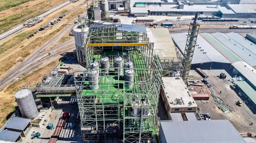
P15

    IN BRIEF
    Photo-luminescent / glow-in-the-dark concrete polymers����������������������������������������������������������������������������������������������������������������43

    Powering Africa – a local perspective ��������������������������������������������������������������������������������������������������������������������������������������������������������������������������������� 44

    Award-winning university building incorporates Corobrik’s face brick for effect ���������������������������������������������45

    Concor Buildings – constructing Oxford Parks Phase I������������������������������������������������������������������������������������������������������������������������������� 46

    SAICE AND PROFESSIONAL NEWS
                                                                                                                                                                                                                                                   P22
    A new decade, a new relationship between SAICE and IStructE ��������������������������������������������������������������������������������������������������49

    Introducing the new SAICE Structural Division��������������������������������������������������������������������������������������������������������������������������������������������������������50

    The Candidate Academy™ – celebrating ten years of service excellence������������������������������������������������������������������������52

    Obituaries – Francis Legge and Carlos Ribeiro da Silva ������������������������������������������������������������������������������������������������������������������������������56

    SAICE Training Calendar 2020 ������������������������������������������������������������������������������������������������������������������������������������������������������������������������������������������������������������58

                                                                                                                                                                                                                                                   P36

    P32                                                                                                                                                                                                                                            P46
                                                                                                                                                                                                                                                          3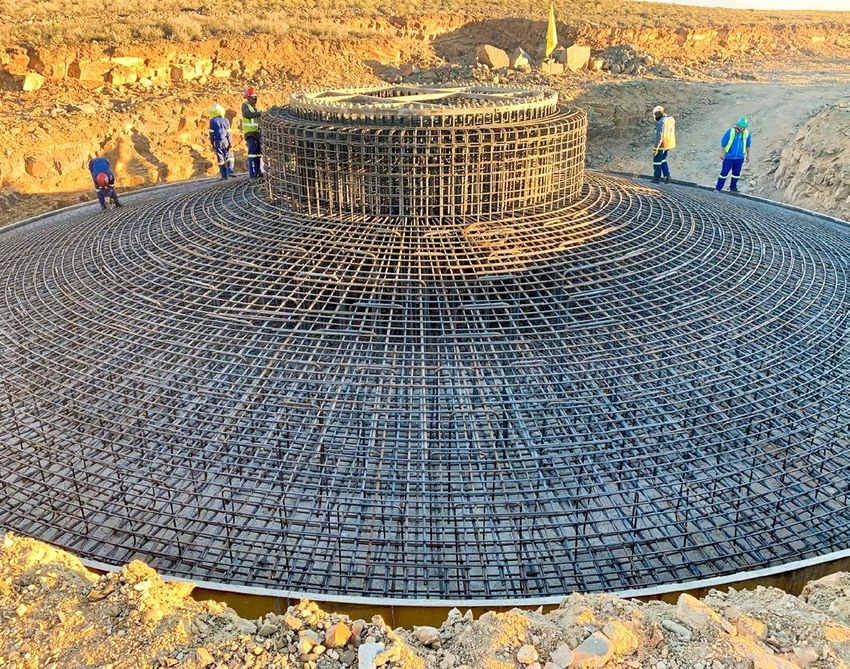
O N T H E COV E R

 TRM Piling –
 designed and installed
 TRM Piling’s success to date with clients        Table 1 UMK Screening Plant Upgrade, Hotazel, Northern Cape, 2019
 has been achieved based on quality, safety,       Project Description    UMK Process Screening Plant Uprade
 mutual trust and respect. Since being in-
                                                   Structural engineer    DRA Projects (Pty) Ltd
 troduced into the African market almost
 a decade ago, the TRM piling system has                     Location     Hotazel, Northern Cape, South Africa
 been selected and successfully used at                                   The site consisted of aeolian sand (5–13 m), overlying interlayered
                                                         Geotechnical
 numerous challenging projects across                                     calcareous sands including well-developed calcrete, overlying banded
                                                           conditions
 South Africa and the African continent,                                  ironstone at great depth.
 including piling for transmission lines,              Pile loads (SLS)   V+ (max) = 475 kN; V– (max) = –140 kN; H (max) = 47 kN
 bridges, silos, conveyors, screening plants,
                                                                          TRM 118/7.5 socketed piles were installed into competent calcrete to
 tanks, heritage sites, various mines, car                                achieve geotechnical load transfer. Socketed TRM piles designed to
 dealerships, office buildings, apartment           Technical solution    penetrate several metres into competent calcrete (penetration variable
 blocks, retrofits and several types of                                   depending on actual weathering condition of in-situ material at each
                                                                          specific pile position). The design allowed an average pile length of 10 m.
 power plants.
                                                                          Operating mine, piling within a processing plant alongside active
 RISK REDUCTION                                                           conveyors and screening plants. Restricted piling locations, very close to
                                                           Challenges     existing structures. Limited working space. Buried underground services.
 The TRM piling system offers total
                                                                          Fast-track programme required by the client. Variable ground conditions.
 versatility between end-bearing and                                      Extremely tight piling shedule (to ensure plant outage date could be met).
 friction-pile systems for geotechnical
 load transfer. This makes it a dependable,
 flexible and adaptable system of choice
 to minimise risks in case of limited
 geotechnical information or unexpected
 variations. Pile depth/length adjusts auto-
 matically to match actual unique sub-soil
 conditions encountered at each individual
 pile location.
     Classified as displacement piles and
 using a high-frequency hammer, vibration
 is minimal (normal peak particle velocity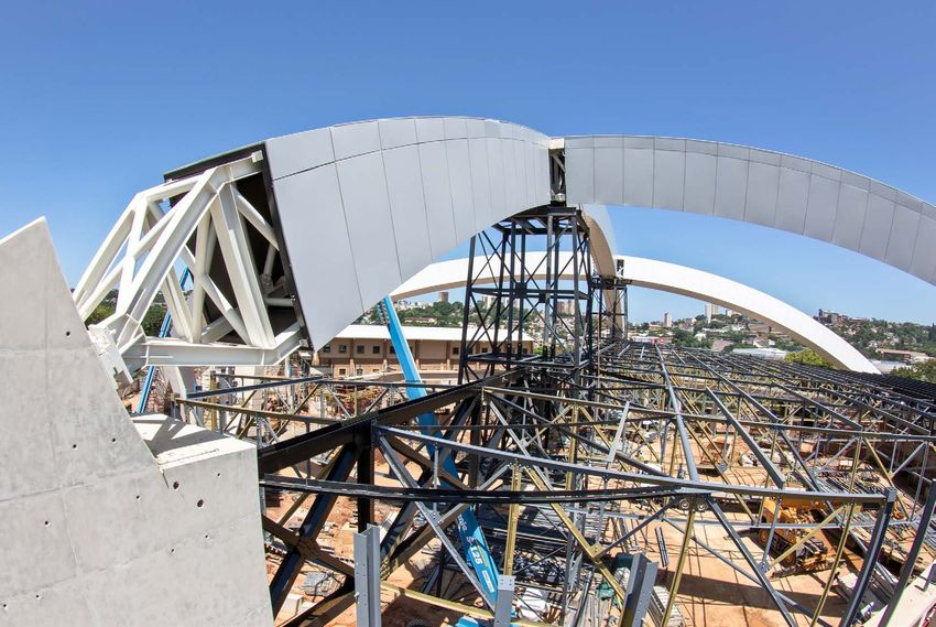
Table 2 Burbec, Apartment Blocks, Pretoria, 2019

        Project Description     Residential Building – apartment block

       Structural engineer      Engineering Design Services (Pty) Ltd

                    Location    Silver Lakes, Preotoria, Gauteng, South Africa

  Geotechnical conditions       Fill overlying shallow soft rock shale bedrock

                                TRM 170/9: V+ (max) = 810 kN
             Pile loads (SLS)
                                TRM 118/7.5: V+ (max) 560 kN

                                Combination of TRM 118/7.5 and TRM 170/9.5
                                end-bearing piles installed into competent
         Technical solution
                                bedrock in order to achieve geotechnical
                                load transfer.

                                Residential area, with nearby businesses.
                                                                                                    Burbec apartment blocks – sloping site
                 Challenges     Highly variable ground condition. Sloping
                                                                                              with cut-and-fill terraces, with sub-structure
                                site with cut-and-fill terraces.
                                                                                            works following immediately after piling works

Table 3 K69, River Bridge, Pretoria, 2019
        Project Description     K69, River Bridge 5358

       Structural engineer      GKB Design Associates (Pty) Ltd

                    Location    Mamelodi, Pretoria, Gauteng, South Africa

                                Residual shale with very soft to soft rock
  Geotechnical conditions
                                shale bedrock expected at 5 m depth.

                                Abutment: V+ (max) = 1 010 kN
             Pile loads (SLS)
                                Pier: V+ (max) = 1 041 kN

                                TRM 170/9 end-bearing piles installed into
         Technical solution     competent bedrock for geotechnical load
                                transfer. Estimated average pile length 6.5 m.

                                Uneven and soft working platforms with
                                groundwater at surface.
                 Challenges
                                Tight piling schedule to ensure piles were
                                                                                     K69 River Bridge – uneven and soft (saturated) working
                                installed before the summer rains arrived.
                                                                                   platforms, with piling completed prior to summer rains

Table 4 Kusile Power Station Conveyor Upgrade, Delmas, Mpumalanga, 2019

        Project Description     Kusile Power Station Conveyor Upgrade

       Structural engineer      ASD Consulting Engineers

                    Location    Delmas, Mpumalanga, South Africa

                                Fill overlying shale bedrock at approximately
  Geotechnical conditions
                                5 m depth

                                V+ (max) = 665 kN; V– (max) = –145 kN;
             Pile loads (SLS)
                                Horizontal (max) = 15 kN

                                TRM 118/7.5 socketed piles installed into
                                competent bedrock in order to achieve
                                geotechnical load transfer. The socketed TRM
         Technical solution
                                piles were designed to penetrate up to 3 m
                                into the competent shale, with average pile
                                length being 10 m.

                                Operating power station. Restricted working
                                space of piling locations very close to existing
                 Challenges     structures, limited space and headroom.
                                Buried underground services. Tight piling                    Kusile Power Station Conveyor Upgrade –
                                shedule.                                                   restricted piling locations, very close to existing
                                                                                        structures, with buried underground services

Civil Engineering March 2020                                                                                                               5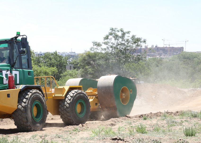
Table 5 765 kV Line Ankerlig to Sterrekus, Western Cape

         Project Description     ESKOM 765kV line Ankerlig to Sterrekus, Western Cape, South Africa

         Structural engineer     ESKOM

                    Location     Melkbosstrand, Western Cape, South Africa

                                 Loose saturated sand for the upper 3–4 m, becoming medium-dense to
     Geotechnical conditions
                                 dense thereafter with calcrete lenses interspersed sporadically.

             Pile loads (SLS)    V+ (max) = 529 kN; V– (max) = –437 kN

          Technical solution     TRM 118/7.5 friction piles with 270 mm shoe. Average pile length 12 m.

                                 Saturated variable ground conditions. Remote site locations. Climate –
                                 winter. Sand dunes with protected flora – limited working platforms.
                 Challenges      Vehicles getting stuck and needing to be towed. Planning of concrete
                                 trucks – batching plant fair distance away.
                                 Low overhead locations.                           765 kV Line Ankerlig to Sterrekus – remote site locations with limited
                                                                                       working platforms, including wet and saturated ground conditions

load and quality testing. Additionally, the              FURTHER SIGNIFICANT COST                              solutions throughout South Africa and
exceptional corrosion resistance of ductile              AND TIME SAVINGS POSSIBLE                             the wider region.
iron pile material guarantees a structural               By selecting and awarding the TRM                        The TRM piling system has been used
service life of up to 100 years.                         piling system from an early stage, further            and accepted by many highly regarded
                                                         significant cost and time savings are also            professional entities including ACSA, ASD
TIME AND SCOPE SAVINGS                                   being achieved. Closer pile centres of TRM            Consulting Engineers, Arup, Aurecon, BA
BEFORE, DURING AND AFTER                                 piles, with reduced inter-pile span distances,        Engineers, BIGEN Africa, DRA Projects,
PILING EQUATES TO SIGNIFICANT                            enable the sub-structure dimensions to                EDS Consulting, ESKOM, GKB Design
CLIENT COST REDUCTION                                    be value-engineered, resulting in overall             Associates, Greene Group, Jones & Wagener,
Fast mobilisation and site set-up of light-              volume reductions of potentially up to 80%,           Kantey & Templer, LNW Consulting
weight mobile equipment enables imme-                    and major time and cost savings.                      Engineers, Moroff & Kuhne, Mosomo, Mott
diate access and commencement of piling                      The TRM piling system has brought                 Macdonald, PRASA, RHDHV, SASOL,
works on site, even under challenging                    value engineering solutions to many deep              SRK, V&H Consulting Engineers, VNA
conditions. Using compact and versatile                  foundation projects over recent years (see            Consulting and many more.
piling equipment, the TRM piling system                  Tables 1–7 for examples).
accesses challenging working positions,                                                                          Info
and reaches down into pre-excavated                      IN CONCLUSION
pilecap (sub-structure) excavations. Being               During the past decade, the TRM PILING                  Tyrone Shuttleworth
a full-displacement piling system, the sub-              SYSTEM has earned a well-established                    Lanseria Head Office
                                                                                                                 +27 74 310 1111
soil is also compacted, with no piling spoil             track record for high-quality deep                      tyrone@trmpiling.com
or debris left behind.                                   foundations engineering applications and

Table 6 East Point Mall, New Decathlon Building, 2019                                          Table 7 Stand 188, Apartment Blocks, Kempton Park, 2019

                           Retail Shopping Mall Retrofit – existing structure that               Project Description    Residential Building – apartment block
 Project Description
                           had been partially demolished
                                                                                                 Structural engineer    V&H Consulting Engineers
 Structural engineer       LNW Consulting Engineers
                                                                                                           Location     Kempton Park, Gauteng, South Africa
              Location     Boksburg, Gauteng, South Africa
                                                                                                                        Colluvium layer blanketing the site
                           Fill, overlying clayey silty sand (residual sandstone),                                      with a pebble marker layer. Loose
                           overlying firm to stiff clayey silt (residual shale), overlying             Geotechnical     to medium dense nodular ferricrete
          Geotechnical
                           either soft rock shale bedrock or soft rock diabase                           conditions     with collapsible potential. Depth to
            conditions
                           bedrock, shallow water table approximately 4 m below                                         the competent shale or basaltic lava
                           site surface.                                                                                bedrock estimated at 8–10 m.

        Pile loads (SLS)   V+ (max) = 419 kN; V– (max) = –50 kN                                      Pile loads (SLS)   V+ (max) =1 358 kN

                           TRM 118/7.5 end-bearing piles installed into competent                                       Combination of TRM 118/7.5 and TRM
     Technical solution    bedrock in order to achieve geotechnical load transfer.                                      170/9 end-bearing piles installed
                           Average pile length 12 m.                                              Technical solution    into competent bedrock in order to
                                                                                                                        achieve geotechnical load transfer.
                           Operating shopping mall. Limited access due to building                                      Average pile length 8 m.
                           not being fully demolished. Piles installed next to existing
            Challenges
                           structures and services. Restricted headroom. Highly                                         Residential area, with nearby
                                                                                                         Challenges
                           variable geotechnical conditions throughout the site.                                        businesses. High groundwater table.

6                                                                                                                                  March 2020 Civil Engineering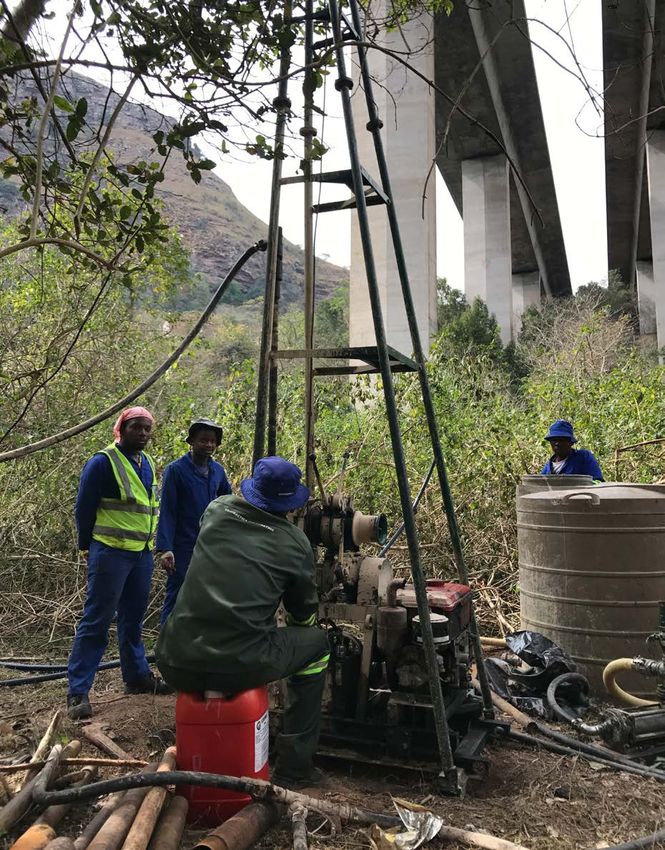
RETAIN
Reinforced Earth® retaining structures
are custom designed to meet unique
technical and environmental requirements.
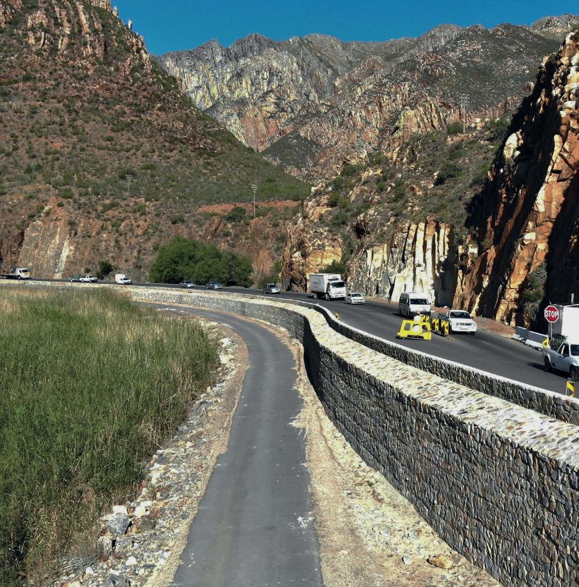
An upgraded section of the historic character of the pass, infrastructure
Cogmanskloof Pass, which was firm AECOM combined Reinforced
originally designed by Thomas Bain Earth TerraTrel® retaining walls with
in the mid 1870s, runs through local stone cladding. This technical
the Langeberg Mountains of the and aesthetic solution provides an
Western Cape. Being sensitive to improved experience for road users
preserving the historic and scenic of the pass.
Reinforced Earth® RETAIN, CROSS and PROTECT techniques are used for the following applications:
Bridge Abutments, overpasses & underpasses, approach ramps, access road and railway retaining walls, dump walls,
storage bunkers, reclaim tunnels, reservoirs…
Contact our team and let us know about your next project. Email: resa@recosa.co.za Phone: +27 11 726 6180
Reinforced Earth Applications
Reinforced Earth (Pty) Ltd South Africa
2nd Floor, 1 Park Road,
Roads Railways Rivers Ports Water Dams Mining Construction Energy Richmond, Johannesburg
& Motorways & Waterways & Coastal works management & Reservoirs & Minerals materials
Tel: +27 11 726 6180
www.recosa.co.za - www.terre-armee.com
Industry Land development Airports Waste Environmental Military Sports Bridges
& Building management & Leisure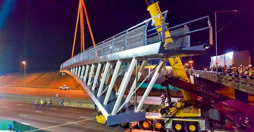
STRUC TURAL ENGINEERING

 Interaction between the bridge and
 geotechnical engineer – finite element
 modelling of rock foundations
           Dylan Fourie                            the top of the piers, resulting in significant   relatively low shear strengths, and most
           Master’s Graduate                       load redistribution between piers.               rocks contain them (Wyllie 1999).
           Geotechnical Engineering                    It is therefore proposed that the analysis       A rock mass cannot be tested to deter-
           Stellenbosch University
           dfourie13@gmail.com                     process is, and should be, an iterative pro-     mine if the rock is suitable to be used as
                                                   cess between the structural and geotech-         a support for massive structural loadings,
                                                   nical engineer, as settlement and distortion     as there is rarely a rock specimen that is
                                                   are best estimated by the geotechnical           dependable enough to fully represent the
           Nanine Fouché
           Department of Civil Engineering
                                                   engineer, whilst load take-down due to           entire rock mass from which the results
           Stellenbosch University                 these varying foundation stiffnesses is best     had been extracted. Numerical model-
           naninef@sun.ac.za                       estimated by the structural engineer. This       ling techniques are able to simulate the
                                                   iteration should continue until convergence      possible conditions of the rock mass with
                                                   is reached between the two models. This          the information obtained from field inves-
                                                   study aimed to compile a guideline to            tigations and laboratory testing on intact
           Frans van der Merwe Pr Eng
           Principal Geostructural Engineer
                                                   optimise the iteration process between           rock and discontinuities respectively. A
           GaGE Consulting                         the geotechnical and structural engineer,        geotechnical FEM software, Rocscience’s
           frans@gageconsulting.co.za              and to assist the geotechnical engineer in       RS3 (Figure 1), was used as a tool to model
                                                   improving the consistency in the finite          the foundation system, including the
                                                   element modelling (FEM) of the interac-          rock mass beneath a foundation using an
 OVERVIEW                                          tion between the structure and the rock.         appropriate constitutive model to take the
 The design and modelling of foundations           This was achieved by modelling a bridge          structure and joint surface conditions into
 cross two civil engineering disciplines,          footing on rock using a 3D geotechnical FE       account. Figure 2 shows the subsurface
 namely structural and geotechnical                software package, obtaining the footing’s        investigation on the proposed widening of
 engineering. The structural engineer goes         settlement and rotation, deriving structural     a tall bridge structure.
 into great detail when sizing foundations         springs and inserting these revised springs          When designing bridge foundations,
 to ensure effective load transfer from the        back into a structural FE software package       the interaction between the structural
 superstructure to the underlying geoma-           to determine the revised load takedown.          engineer and the geotechnical engineer
 terials. This is usually accomplished by          This should result in more realistic and         should be an iterative process. An effec-
 deriving the load and moment taken down           accurate modelling by the bridge engineer.       tive way is needed to guide the geotech-
 from the superstructure onto the founda-                                                           nical and structural engineer through
 tion. This load takedown is normally              INTRODUCTION                                     the iterative process, as incorrect spring
 established as a first estimate based on          Large bridge structures require suitable         values could result in significantly un-
 either a fixed-base or an assumed springs         support from the geomaterials beneath            derestimated loads on foundations. From
 stiffness model in structural finite element      them. Due to the ability of rock to with-        experience it is known that differences of
 (FE) analysis. The loads transferred from         stand immense shear and tensile loading,         10–25% in axial load and bending moment
 the superstructure to the various piers and       structures such as bridge piers and dams         can be expected.
 foundations will vary depending on the            are more frequently founded on rock as an            The purpose of this article is to guide
 fixity assumed by the structural engineer,        alternative to soil. However, caution must       the geotechnical and structural engineer
 and could result in large discrepancies           be exercised when constructing founda-           to better understand the influence of
 when modelled with the same stiffness             tions on rock, as a single low-strength          foundation stiffness on the behaviour
 when certain foundations are stiffer than         discontinuity in the rock mass at a certain      of foundations on rock, the constitu-
 others. This becomes more critical in large       orientation may cause total failure of the       tive models that are applicable for rock
 bridge structures with tall piers where even      rock. These discontinuities range from           foundations and the required interaction
 the slightest differentials in displacement       joints with rough surfaces that have sub-        between the structural and geotechnical
 at the base of adjacent piers could lead to       stantial shear strengths to massive faults       engineers when designing bridge founda-
 significant differential tilt and settlement at   that contain various kinds of clays with         tions. This will be achieved by modelling

 8                                                                                                                   March 2020 Civil Engineering
Figure 1 RS3 model of foundation on rock
a bridge foundation with RS3 geotechnical
FE software using geotechnical constitu-
tive models, obtaining the footing’s
settlement and distortion, and deriving
foundation structural springs.
ECCENTRIC LOADING ON Figure 2 Subsurface investigation on
BRIDGE FOUNDATIONS proposed widening of a tall bridge structure
AASHTO (2002) recommends that the
eccentricity, e, of the resultant force on It should however also be remembered value uniformly below and between
a spread foundation be kept to e ≤ B∕6 that these allowable bearing capacities different foundations.
and e ≤ B∕4 for foundations on soil and are normally derived taking the footing For illustration purposes, a crude
rock respectively (where B = foundation geometry into consideration. hand calculation for settlement is given
width or length). This check is normally On strong rock, especially on bridge below to compare two footings with the
undertaken in the Serviceability Limit foundations, it is assumed that the over- same applied stress and soil stiffness in
State (SLS) and implies that a foundation turning will govern the design, whilst the order to show that the subgrade modulus
on soil may not have any “uplift” whilst a pressures on the edges of the foundations varies depending on the geometry – the
foundation on rock may have 25% “uplift”. will not be close to the allowable bearing first with a footing width of B = 0.6 m, an
The concept of limiting eccentricity to capacity of the rock, which is normally applied stress of σ = 200 kPa and a soil
e ≤ B∕6 is based on the premise that the very high. stiffness of E = 10 MPa, and the second
geotechnical engineer normally provides with a footing width of B = 7 m.
the structural engineer with an allowable ABUSE OF SPRINGS The settlement is assumed to be
bearing pressure, qall. Assuming the Springs are widely used by structural given by:
Factor Of Safety (FoS) on this allowable engineers to model soil-structure interac-
bearing pressure is 3, the maximum tion in structural modelling packages to 0.9Bσ
δ=
pressure below the foundation with an ec- represent the stiffness of the foundation E
centricity of B∕6 will be 2qall (FoS = 1.5 on soils. Soils and rock exhibit non-linear
the edge of the foundation). Similarly in stress-strain behaviour. Typically, The settlement for the 0.6 m wide footing
the Ultimate Limit State (ULS) the eccen- subgrade moduli from standard tables, was calculated as:
tricity could be limited to B∕3.6, assuming such as those provided in Bowels (1996)
the maximum pressure below the edge of are used without understanding that 0.9(0.6)200
δ= = 10.8 mm
the foundation will be 3qall, but this could subgrade moduli are not constant values 10
potentially result in significant rotation of and vary with applied load and footing
the foundation and increased P-δ (P-delta geometry. Key to appreciate, is that a The subgrade reaction is then calculated as:
second order effects) moments on the subgrade modulus is not a soil property, it
foundation that could result in pressures is not constant below foundations, and it 200 (1 000)
ks = = 18 518 kN/m3
exceeding 3qall. is also not conservative to use the lowest 10.8
Civil Engineering March 2020 9Whereas, the settlement for the 7 m wide
footing was calculated as δ = 126 mm, and 0
the subgrade reaction as:
–0.05
ks = 1587.3 kN/m3.
In addition to the above, if the applied
–0.10
stress was changed, the Young’s modulus
Deflection (mm)
would change, as the stress-strain behav-
iour is non-linear, and Young’s modulus –0.15
will decrease with an increase in strain.
Considering the above, a structural
model using springs assumed from the –0.20
above could result in erroneous load take-
down, assumed differential vertical settle-
–0.25
ments and predicted tilt which for tall or
large structures could be problematic and
inaccurate.
–0.30
0 1 2 3 4 5 6 7 8 9
RELEVaNT CONSTITUTIVE Footing length (m)
MODELS FOR ROCK Rigid half load Rigid full load Rigid double load
Constitutive models describe a material’s Semi-flexible half load Semi-flexible full load Semi-flexible double load
response to different loading conditions,
such as mechanical loads, which in turn Figure 3 Deflection of semi-flexible vs rigid footing loaded on footing geometry
provide the stress-strain relations of the
material to formulate governing equations but the materials on which it rests as degree of flexibility, and thus when a
(Zhang et al 2017). The Hoek-Brown (HB) well (Chen & Duan 2014). Foundation pressure or concentrated load is ap-
failure criterion is one of the most widely systems are complex, as there are different plied, the footing undergoes bending.
accepted failure criteria used to estimate constituents, each with variable material As the flexible footing bends, the soil
rock strength. However, the original HB properties interacting with one another beneath the footing settles differen-
failure criterion is limited in many ways (Lemmen et al 2016). With the exception tially and leads to a non-linear pressure
and has thus been adapted and expanded of unusual conditions, design codes such distribution.
over four decades to allow the criterion as the TMH7 Part 3 (1989), allow a varying Contact stress beneath a flexible footing
to be used for an extensive range of rock linear soil pressure distribution to be is also highly dependent on soil type,
properties. The Generalised Hoek-Brown assumed for eccentrically loaded footings. whereas the settlement is nearly uniform
(GHB) failure criterion is the most widely This represents rigid behaviour. The actual for all types of soil. The rigidity behaviour
accepted constitutive model for a con- behaviour can be tested in 3D geotechnical of the foundation was tested in two
tinuum rock mass. It appears to provide FE models using geotechnical constitutive ways namely:
the most reliable set of results for use as models, as discussed below. QQ Applying only uniform stress (of
input for methods of analysis currently Experience has demonstrated that varying magnitude) on a rigid
used in rock engineering (Hoek 2001). the assumption of a linear pressure foundation (concrete E = 1 × 10⁶ GPa)
The GHB parameters were based on the distribution is adequate for the majority and on concrete of normal stiffness
subsurface investigation logs, geophysical of cases because of the conservative (E = 30 GPa).
test results and laboratory test results for load estimates and safety factors in the QQ Applying only axial load on top of
the specific example. If jointing or dis- materials. However, there are also cases the pier using both E = 30 GPa (semi-
continuity planes govern the behaviour of where the footing must be analysed flexible) and E = 1 × 10⁶ GPa for the
the founding rock, these should be added as a flexible structure, specifically for foundation dimensions and rock prop-
into the FE model and the foundation long, thin or wide foundations (Tabsh & erties discussed in the next section.
modelled as a discontinuum mass. Al-shawa 2005). The results are provided in Figure 3 and
One of the most important aspects Figure 4 respectively, where it can be
FOUNDATION STIFFNESS of the rock-soil interaction is the contact established that the true foundation prop-
The term foundation is often used to stress distribution and settlements beneath erties (E = 30 GPa) will result in flexible
describe the structural component that the footing, which will vary as follows: behaviour for the specific example, whilst
transmits the weight of, and loads acting QQ Rigid footing settlement is nearly the settlements almost doubles when
upon, the entire structure onto the ground. uniform for all types of soil, whereas modelling the pier and the foundation in
However, this is not a fitting description the contact stress beneath the footing combination. It should be appreciated that
for a foundation, but is just one aspect of is highly dependent on soil type. the displacements on rock might be small,
a system, as the foundation system incor- QQ In the case of a flexible footing, the but adjacent foundations could be piled and
porates not only the concrete component, footing is considered to have some displacements much larger, resulting in
10 March 2020 Civil EngineeringMODEL SETUP
0 A bridge footing of a tall pier (>80 m) on
rock was modelled using Rocscience’s RS3
–0.10 geotechnical FE software; the main reason
being that RS3 contains built-in constitu-
tive models used to accurately model rock
–0.20
behaviour such as the Hoek-Brown and
Generalised Hoek-Brown failure criteria.
Deflection (mm)
–0.30 The geometry of the spread footing was as-
sumed to be 9 m × 7 m, and 2 m thick. The
–0.40
geometry and dimensions of the bridge
footing and bridge pier were modelled. The
footing is subjected to eccentric loading
–0.50 due to wind forces, launching loads, dy-
namic forces applied from moving vehicles
–0.60 on the bridge deck, as well as seismic
loading. The foundation was assumed to be
on very hard rock (granite-gneiss) with an
–0.70
0 1 2 3 4 5 6 7 8 9 allowable bearing pressure of 16 000 kPa.
Footing length (m) The SLS loading applied to the footing
Rigid half load Rigid full load Rigid double load was modelled and is summarised in
Semi-flexible half load Semi-flexible full load Semi-flexible double load Table 1.
Figure 4 Deflection of semi-flexible vs rigid footing loaded on the pier geometry Table 1 Loading applied to bridge pier
SLS Loading
Load Magnitude Unit
1.60
Nx 20 600 kN
1.40
Mz 46 000 kN.m
Centre displacement / Edge displacement
1.27
1.20 My 38 000 kN.m
1.07
1.00 Vy 925 kN
Vz 108 kN
0.80
0.40 The derived springs will differ in the ULS.
The foundation system can be modelled
Current example
0.60 in two ways:
QQ the first being to model the entire pier
0.20
(assuming E = 30 GPa or 1 × 10⁶ GPa),
and reviewing displacements on
0
0 1.0178 2 4 4.4089 6 8 10 10.86 12 the edge of the pier or foundation,
Rock stiffness (GPa) depending on rigidity, and
QQ the second being to model the vertical
Figure 5 Influence of rock stiffness vs footing flexibility forces (N) and bending moments (M)
as a single vertical load, eccentrically
much larger differential tilt and displace- changed. Figure 5 compares the displace- placed on the foundation (lever arm)
ment between piers on rock and piles. ment at the centre of the footing with the with E = 1×10⁶GPa. This high E was
Therefore, the influence of rock stiff- displacement at the edge of the footing for used, as a stress concentration on the
ness on the deformation of the footing different rock stiffnesses. foundation will result if E = 30GPa
was investigated – as this is theoretically Figure 5 illustrates that the stiffer was assumed, resulting in local failure.
the only parameter that can influence the rock material is, the more flexible This load at an eccentricity was
the behaviour, because concrete’s stiff- the footing behaves. This shows that a modelled to account for the bending
ness will vary between 15 and 30 GPa simplified point load method, assuming moments without modelling the entire
depending on creep and cracking of the E = 1 × 10⁶ GPa with an applied ‘point bridge pier, thus making the model
section. This involved the same vertical load’ at an eccentricity, might not be simpler. The biaxial eccentricity was
stress (full load) being applied to the pier valid, and the flexibility of the foundation calculated around both axes, looking
geometry on the semi-flexible footing, should be checked before using such at displacements at the edges of the
while the stiffness of the rock was a method. foundations, using:
Civil Engineering March 2020 11Iteration 1 Iteration 2 Iteration 3
Settlement
in centre and
corners of footing Settlement
Geotechnical model in centre and Settlement
corners of footing in centre and
corners of footing
New springs New springs New springs
New loads New loads
Re-run structural
Re-run structural model and
model and assess load
Structural model
Re-run structural assess load re‑distribution
model and re‑distribution
Initial loadset
assess load
re‑distribution
Model Convergence
Figure 6 Iteration process between geotechnical and structural engineers
M
e=
N
A
STRUCTURAL SPRINGS DERIVATION
As a first step, the structural engineer
provides the geotechnical engineer with
the proposed foundation geometry (based
on ABP) and a load set derived from
either a fixed based or assumed spring E C
value structural analysis. These loads
B
are inserted into the geotechnical 3D FE
model to determine the settlement and
distortion, whilst the rock properties are L
based on subsurface investigation and
B
laboratory results. Thereafter, new springs
are calculated and given to the structural X
engineer. This section will show the deri- Y
D
vation of the equations used to calculate Z
the new springs. The iteration process is Figure 7 Query points where settlement was reviewed
illustrated in Figure 6.
The loads in Table 1 were inserted into Nx rotational spring around the z-axis kφz
kv =
the RS3 model. As stated in the TMH7 δcv (kN.m/rad) was derived by dividing the
Part 3 (1989), the footing was assumed to applied moment about the z-axis by
be rigid, with the loading applied to the The lateral springs in the z and y direc- the average angle of rotation φz in the
top of the column. The model was run tions (kN/m) are similarly derived by direction of the applied moment (as the
and the vertical and lateral movements dividing the lateral load applied to the moment is causing the rotation). The
were computed. Thereafter, the settle- footing (in the respective direction) by the average angle of rotation about the z-axis
ments at the bottom four corners and the lateral movement in the same direction at φz (radians) is derived by:
⎧ (δA – δE) + (δB – δD) ⎧
middle of the footing, as well as the lateral point C δcz and δcy respectively:
⎪ ⎪
⎩ ⎩
movements in the middle of the footing
(Figure 7), were recorded. Vz 2
kz = φz = tan–1
Once the settlements were obtained δcz B
from the RS3 computation, the vertical,
lateral and rotational springs were Vy The rotational spring around the z-axis
ky =
derived. The vertical spring k v (kN/m) δcy kφz:
was derived by dividing the vertical load
applied to the footing, by the vertical set- Thereafter, the rotational springs around Mz
kφz =
tlement at point C δcv: the respective axes were derived. The φz
12 March 2020 Civil EngineeringSimilarly, the rotational spring around Table 2 Derived spring values
the perpendicular axis can be determined Springs
by taking the average distortion around
Description Symbol Value Unit
that axis.
Vertical spring in X kv 116.9 GN/m
STRUCTURAL SPRING RESULTS Horizontal spring in Z kz 8 GN/m
The springs derived using the settlements
and lateral movements obtained from the Horizontal spring in Y ky 69.2 GN/m
RS3 model are presented in Table 2. These Rotational spring around Z kφz 1 431.4 GN.m/rad
values differ up to 4 000% from those
Rotational spring around Y kφy 2 039.4 GN.m/rad
values calculated using subgrade moduli
from Bowles’ standard tables.
GUIDELINE FOR GEOTECHNICAL Determine Allowable
ENGINEERS Bearing Pressure (ABP) using
The guideline illustrated in Figure 8 first order methods
was developed to assist the geotechnical
engineer when analysing bridge spread
foundations on rock or piles using finite
Send ABP to structural
element analysis as a numerical modelling engineer to determine initial
tool. This guideline should be followed by footing size
the geotechnical and structural engineer
Receive initial loadset from bridge engineer
to assist in the iteration process.
PASSIVE ROCK DOWELS
To prevent possible uplift of the footing Assess rigidity of footing*
due to overturning moments, passive Rigid Not rigid
rock dowels can be added to the footing
according to simple limit equilibrium Model the footing using
Model the entire pier
hand calculations. Two rows of 40 mm the simplified point load
geometry on the footing
method
diameter dowels, each row consisting of
seventeen 3 m long dowels, were inserted
along the length of the footing, as shown
Derive structural springs
in Figure 9. The dowels were modelled
as bolts in RS3. A sensitivity analysis was
carried out to determine the effect of rock
stiffness on the amount of tensile force Provide structural engineer Receive new loadset
with derived springs from bridge engineer
attracted by the dowels for footings of
differing stiffnesses on rock of differing Receive new loadset from bridge engineer
stiffnesses. Figure 10 illustrates the mag-
nitude of axial force the dowel closest to
the point of uplift will attract for footings
Is convergence reached* No
with 7 GPa, 30 GPa and rigid foundation
stiffnesses on weak, intermediate and
strong rock (rock strength determined by
stiffness, E). Yes
Figure 9 shows that the less stiff the
rock is, the more force the dowels will Moment loading and axial
loading are accurate
attract. Additionally, the less stiff the
footing is, the more force the dowels
will attract. However, for this specific Figure 8 Guideline for assisting in the FEM of bridge footings on rock
foundation system, the tensile loads in
the dowels are low compared to those that the use of passive dowels is a strain CONCLUSIONS
calculated by the Limit Equilibrium (LE) compatibility issue and that LE methods A guideline was developed to optimise
hand calculation to prevent uplift. This might over-predict the ‘positive’ effect the iteration process between the
is due to insufficient settlement below of passive dowels, and that the founda- geotechnical and structural engineer to
the compression corner of the foundation tion should rather be increased in size assist them to improve the consistency
and corresponding small uplift displace- if uplift is considered problematic on in modelling the interaction between the
ment in the opposite corner. This shows stiff rock. bridge structure and the foundation.
Civil Engineering March 2020 13the contact pressure beneath the
footing is not linear.
QQ It was shown that if a footing is clas-
sified as rigid, the simplified point
load method can be used to determine
settlements, but when the footing is
classified as flexible, the entire pier
geometry will need to be modelled on
a flexible footing to obtain realistic
results.
QQ The stiffer the rock below a foundation
is, the less force passive dowels will
attract. Additionally, the stiffer the
footing is, the less force the dowels
will attract. The behaviour of passive
dowels is therefore a complex strain-
compatibility problem best modelled
in 3D geotechnical FE.
QQ Analysis showed up to 4 000% differ-
ence in spring stiffnesses assumed,
Figure 9 Passive rock dowels using subgrade moduli form standard
tables.
QQ From experience it is known that the
–2.0 axial load and bending moments can
differ by 10–25% from the original
–2.5 loads.
–3.0 REFERENCES
Bowles, J E 1996. Foundation Analysis and
Dowel length (m)
–3.5 Design. Fifth ed. New York: McGraw-Hill
Companies, Inc.
–4.0 Chen, W & Duan, L 2014. Bridge Engineering
Handbook: Substructure Design. Second ed.
–4.5 Taylor & Francis Group.
TMH7 Part 3 1989. Committee of State Road
Authorities. TMH 7 Part 3: Code of Practice
–5.0
for the Design of Highway Bridges and
Culverts in South Africa. Pretoria, South
–5.5
–7 –6 –5 –4 –3 –2 –1 0 Africa: Department of Transport.
Axial force (kN) Hoek, E 2001. Rock mass properties for
Weak rock – 7 GPa footing Weak rock – 30 GPa footing underground mines. Underground mining
Weak rock – Rigid footing Intermediate rock – 7 GPa footing methods: engineering fundamentals and
Intermediate rock – 30GPa footing Intermediate rock – Rigid footing international case studies, 21: 1–21.
Strong rock – 7GPa footing Strong rock – 30 GPa footing Lemmen, H E, Jacobsz, S W & Kearsley,
Strong rock – Rigid footing E P 2017. The influence of foundation
stiffness on the behaviour of surface strip
Figure 10 Effect of rock stiffness on the axial force of the dowels foundations on sand. Journal of the South
African Institution of Civil Engineering,
The following conclusions were drawn QQ The effect of high rock stiffness on 59(2): 19–27.
with regard to the FE modelling of rock- the foundation resulted in the foun- Tabsh, S W & Al-shawa, A R 2005. Effect of
structure interaction systems: dation behaving in a more flexible Spread Footing Flexibility on Structural
QQ Rock is a non-linear material and, manner. Conversely, if the rock was Response. Practice Periodical on Structural
therefore, a suitable constitutive model weaker, the foundation would behave Design and Construction, 10(2): 109–114.
needs to be chosen in order to accu- more rigidly. Wyllie, D C 1999. Foundations on Rock. Second
rately imitate the rock mass behaviour QQ It was observed and confirmed that ed. Vancouver, Canada: E & FN Spon.
in a geotechnical FE. The Generalised rigid footings undergo uniform settle- Zhang, X, Chen, Z & Liu, Y 2017. Constitutive
Hoek-Brown failure criterion was ment (when subjected to a uniformly Models. In Academic Press: The material
chosen to model the continuum rock distributed vertically applied load), point method: a continuum-based particle
mass for the example in this article. with no differential deflection while method for extreme loading cases. 175–219.
14 March 2020 Civil EngineeringPerdekraal: Pre-clearing and grub area on wind farm
Wind farm projects flying
Concor Infrastructure has, over the past few years, established a sound reference base for the successful
construction of numerous wind farms across South Africa. In this article we look at two of the more recent
projects – the Perdekraal East Wind Farm in the Western Cape and the Kangnas Wind Farm in the Northern
Cape. Although the activities may appear to be repetitive, constructing a wind farm is not always as simple as it
would appear. Different geographical locations present varying site conditions and logistical challenges.
PERDEKRAAL EAST WIND FARM, environmental impact owing to the site’s The Concor and Conco Consortium
WESTERN CAPE straightforward electrical connection into was appointed as the construction
Situated within the Witzenberg Local the Eskom grid. contractors on this project. Marritus
Municipality in the Western Cape, the When operating at full capacity, the Bezuidenhout, Concor Infrastructure
Perdekraal East Wind Farm is less than Perdekraal East Wind Farm will generate construction manager on the site, explains
two hours from Cape Town. Spanning sufficient clean renewable energy to that the project consisted of the construc-
an area of 3 055 ha, the site was selected supply electricity to power up to 95 000 tion of 48 turbine bases and hard stands,
for its excellent wind resource and its South African homes. Each of the 48 maintenance of the existing public district
proximity to national roads for wind tur- wind turbines, standing at a height of gravel road, the construction of 32 km
bine transportation. In addition, studies 115 m, will have blades 53 m long and will of internal roadways and the upgrading
showed that there would be minimal generate 2.3 MW of power. of the existing Kappa Substation, as well
Perdekraal: Processing and compacting material before establishment on site
Civil Engineering March 2020 15Perdekraal: Establishment of the batch plant and office area
as the construction of a new Eskom self- cement replacement, which resulted in a subcontractors, working on the wind farm
build substation. 32.5% reduction in CO2, translating into a project daily, toolbox talks were used to
Work began on site in June 2018, with saving of approximately 1 900 tons of CO2. ensure that everyone was committed to
the scheduled completion of Concor The concrete mix design on the project safe work. In addition to the daily focused
Infrastructure’s portion of the works at factored in that the water in this region has interactions, a mass toolbox talk was
the end of September 2019. a high sulphate content. The first founda- held once a week to refocus the teams by
tion was poured on 22 November 2018 and reflecting on previous work incidents,
Construction of the foundations the last on 17 June 2019. All readymix con- concentrating on identifying risks in the
The region consists of mostly weathered crete was produced at the on-site 40 m3 per coming week’s tasks, and discussing miti-
sandstone and mudstone, and some of the hour batch plant, and in total 25 000 m3 of gation. By June 2019, the Perdekraal East
foundation excavations required blasting. concrete was used on the project. Wind Farm project had achieved 537 532
Each of the 48 wind turbine foundations Lost Time Injury Free (LTIF) man hours.
was excavated to a depth of 3 m and has a Involvement and training of
diameter of 20 m. the local population Responsible environmental stewardship
The majority of the workers respon- Apart from the long-term benefit for the Adherence to sound environmental
sible for constructing the foundations Ceres community from the wind farm, stewardship underpins projects under-
came from the surrounding communities during construction the bulk of the taken by Concor Infrastructure, and an
of Ceres, Nduli, Bella Vista and Prince workforce were drawn from Ceres. Skills important factor on this site was the
Albert Hamlet. A local contractor was development formed an important part aridness of the region which had also just
responsible for cleaning the foundations of the project, with training being done been through a four-year drought. Water
up to the founding or rock level, following with all Concor Infrastructure’s people on was sourced from two boreholes on the
which the blinding was poured using site to ensure that they had the necessary site and, because of the volume and depth
15 MPa readymix concrete. An average of competency and skills. of these, the project received a relaxation
120 m³ per foundation was required due Participation from local companies on the current water usage curtailment.
to the geological conditions. The free- was also a focus. A local bus company However, the water usage was monitored
issue bolt pack, weighing about 12 tons, provided transport for personnel to and continuously, with reports being sent to
was then assembled and put in place. from site. Security was handled by a the Department of Water and Sanitation.
Approximately 50 tons of reinforcing steel security company based within the local Education was again an important
was used in each base. community; awarding the contract to this aspect of environmental stewardship.
Using a shutter created by Concor company enabled it to further develop its This area is the habitat of the critically
Infrastructure, the conical section and the personnel and systems, and increase its endangered Riverine Rabbit (Bunolagus
plinth were poured in a single continuous footprint and coverage. It also allowed Monticularis), more commonly known as
pour. Not only was this an innovation this company to upgrade its equipment to the Bushman Rabbit. It was hoped that by
in turbine base construction, but it also the latest technology available. Aggregate training the local people to identify this spe-
resulted in significant time savings with was brought in from Worcester from a cies, greater awareness of their plight would
the associated cost savings. local Level 1BBBEE contractor. be created. The site was also equipped
Over 400 m3 of concrete was used for with motion sensor cameras to detect and
each base, with 60 MPa being used for the Safety monitor the habitat of these small creatures.
plinth and 40 MPa for the conical section. Safety is, as always, a non-negotiable, and The network of internal roadways
The foundations were designed using a 70% with more than 380 people, including was mapped to avoid sensitive areas that
16 March 2020 Civil EngineeringYou can also read