OCT System Surgical Technique - SPINEMarketGroup
←
→
Page content transcription
If your browser does not render page correctly, please read the page content below
TM

OCT System
Surgical Technique
Contents

Product Overview                                              Product Description                                    2

                                                              Preoperative Preparations                              4

Surgical Technique                                            Surgical Technique                                     5

                                                              Optional Surgical Techniques

                                                                  Laminar Hooks                                     15

                                                                  Compression and Distraction                       16

                                                                  Head to Head Cross Connectors                     16

                                                                  Rod to Rod Cross Connectors                       19

                                                                  Lateral Offset Connectors                         20

                                                                  Parallel Connectors                               20

                                                                  Axial Connectors                                  21

                                                                  Cable Connectors                                  22

                                                              Implant Removal Instructions                          23

                                                              Compatibility                                         24

                                                              SYNAPSE™ OCT System Compatibility                     25

                                                              Occipital Cervical Fusion

                                                                  SYNAPSE OCT System – OC Fusion                    27

                                                                  MOUNTAINEER® OCT Spinal System – OC Fusion        43

                                                              Assembly Instructions                                 50

Indications and Contraindications                                                                                   60

For MR information, please see Symphony IFU 0902-90-161.

                                                           SYMPHONY™ OCT System Surgical Technique   DePuy Synthes    1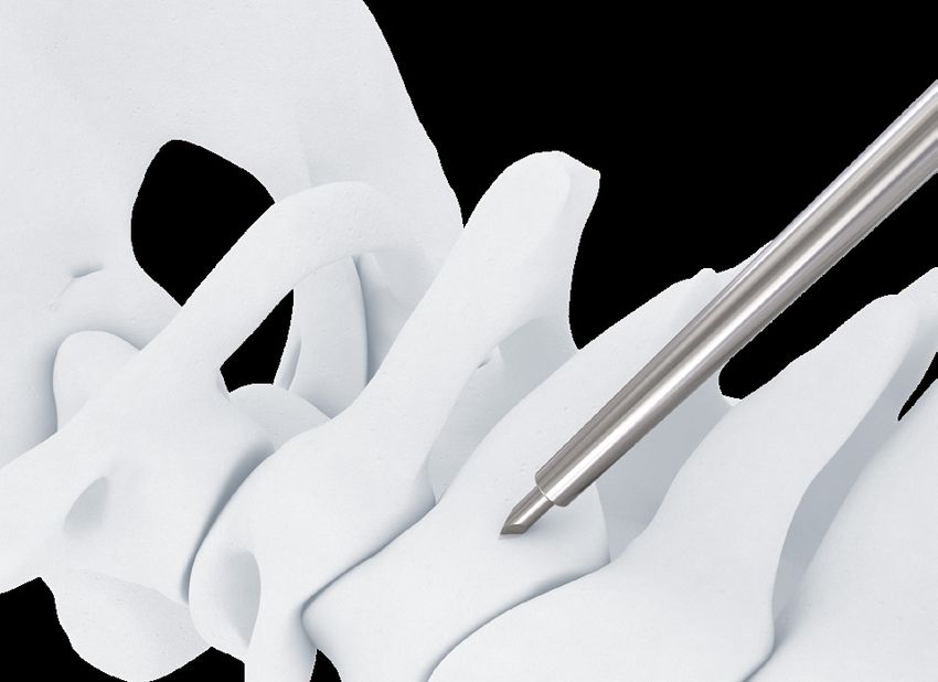
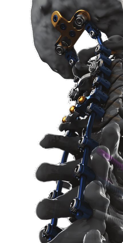
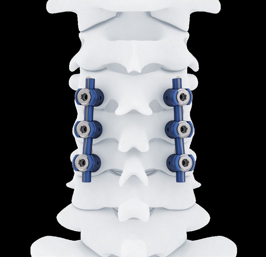
Product Description

Introduction
The DePuy Synthes Spine SYMPHONY™ Occipito-Cervico-
Thoracic (OCT) System is an enhanced set of instruments
and implants, including polyaxial screws, 3.5 mm and
4.0 mm rods, compatible hooks, cross connectors, lateral
offset connectors, and rod connectors designed for
posterior stabilization of the upper spine. The implants
provide the flexibility required to accommodate variations
in patient anatomy.

The DePuy Synthes Spine SYMPHONY OCT System is
compatible with occipital fusion components (plates, rods
and clamps) from the SYNAPSE™ OCT System and the
MOUNTAINEER® OCT Spinal System. Additionally, tapered
rods and connectors are available to extend constructs to
utilize both the DePuy Synthes Spine EXPEDIUM® and
VIPER® Spine Systems.

2   DePuy Synthes SYMPHONY™ OCT System       Surgical Technique
TM

SYMPHONY™ OCT System Surgical Technique   DePuy Synthes   3
Preoperative Preparations

Preoperative Planning
1
Imaging
It is a prerequisite that, due to the anatomic variability of
each patient, the surgeon has available the range of
necessary images in order to plan the operation
appropriately.
Use of cross sectional imaging (i.e., CT and/or MRI) for
posterior cervical screw placement is recommended. The
use of planar radiographs (or fluoroscopy) alone may not
provide the necessary imaging to mitigate the risk of
improper screw placement. In addition, use of
intraoperative imaging should be considered to guide
and/or verify device placement, as necessary.

2
Assemble Instruments
The following instruments must be assembled prior to use:
• Drill Guide, page 50
• Polyaxial Screwdriver, page 54
• AO Handles, page 56
• Reducer Kerrison, page 58

3
Patient Positioning
Patient positioning is critical for cervical posterior fusion
procedures. Place the patient on the operating table in
the prone position with the patient’s head securely
immobilized. Proper patient position should be confirmed
via direct visualization and by radiographs prior to
draping.

4
Approach
Expose the posterior bony elements sufficiently to allow
placement of instrumentation as well as preferred graft
material in and around the decorticated posterior
elements.

4    DePuy Synthes SYMPHONY™ OCT System           Surgical Technique
Surgical Technique

Step 1                                                   Fig. 1
Start Screw Hole

Awl 2.0 mm                                 2020-00-101

Determine the entry point per screw and pierce the cortex
using the Awl 2.0 mm (Fig. 1) or a 2.0 mm high speed
burr.

                                                         SYMPHONY™ OCT System Surgical Technique   DePuy Synthes   5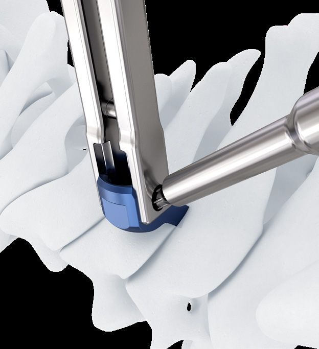
Surgical Technique

Drill Guide-Drill Bit Table

    Screw Size                   Drill Bit                 Code                Drill Guide              Code

     3.0 mm      Long 2.2 mm Drill for 3.0 mm Screw 2020-00-222
                                                                     Long Drill Guide Body 2.2-2.4 mm 2020-00-120
     3.5 mm      Long 2.4 mm Drill for 3.5 mm Screw 2020-00-224
     4.0 mm      Long 2.8 mm Drill for 4.0 mm Screw 2020-00-228
                                                                     Long Drill Guide Body 2.8-3.2 mm 2020-00-123
     4.5 mm      Long 3.2 mm Drill for 4.5 mm Screw 2020-00-232

Step 2
                                                                    Fig. 2
Prepare Screw Pathway
Drill
                                                                                 2
    Drill Guide Modular Handle                     2020-00-119
    Long Drill Guide Body 2.2-2.4 mm               2020-00-120                       1

    Long 2.4 mm Drill for 3.5 mm Screws            2020-00-224

a. Select appropriate drill bit corresponding to the screw
    diameter being used (see above Drill Guide-Drill Bit
    Table) Each drill bit has a color band corresponding to
    the shank of the screw.                                         Fig. 3
b. S et the depth of the Drill Guide Assembly by pushing
    the knob of the Drill Guide Body down and turn
    clockwise to increase the depth (Fig. 2), each activation
    represents a 2 mm adjustment. The depth will appear
    in the window. (Fig. 3) Always confirm depth before
    drilling.
c. Dock the drill tip in the prepared entry point then lower
   Drill Guide onto bone for stability. (Fig. 4)
d. D rill hole to desired trajectory and depth, power may
    be used if desired.

                                                                    Fig. 4
Optional Instrument

    Trocar 2.4mm with Stop                         2020-00-107

Can also be used to create screw pathway

6      DePuy Synthes SYMPHONY™ OCT System      Surgical Technique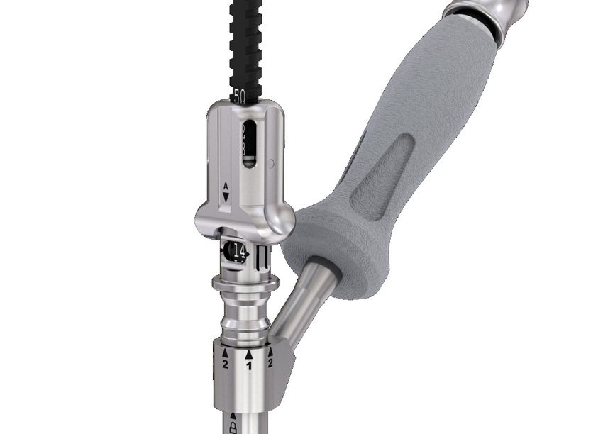
Surgical Technique

Alternative Technique
Probe                                                                                 Fig. 5

 Pedicle Probe 3.2 mm, Straight                               2020-00-158
 Pedicle Probe 3.2 mm, Curved                                 2020-00-159
 Pedicle Probe 2.2 mm, Straight*                              2020-00-102
 Pedicle Probe 2.2 mm, Curved*                                2020-00-103

Pedicle preparation may be done using either the straight or
curved probe. (Fig. 5)

2.2 mm Probes are designed for 3.0 mm, 3.5 mm and
4.0 mm screws
3.2 mm Probes are designed for 4.5 mm screws and above

Step 3
Confirm Depth and Pathway

 Sounding Probe                                                 2025-49               Fig. 6

 Depth Gauge Sleeve with Ball Tip Probe                      2883-03-000
 Small Pedicle Marker-Beaded*                                   389.473
 Small Pedicle Marker-Long Beaded*                              389.474

Use the Sounding Probe to confirm, by palpation, placement
within the bony anatomy.

The Small Pedicle Markers may be used to radiographically
confirm position and orientation of screw sites.

Use the Depth Gauge Sleeve with Ball Tip Probe to confirm hole
depth and select the corresponding screw length. The depth
gauge must sit directly on the bone. (Fig. 6)

* Instrument does not come standard in Core Instrument Set

                                                                     SYMPHONY™ OCT System Surgical Technique   DePuy Synthes   7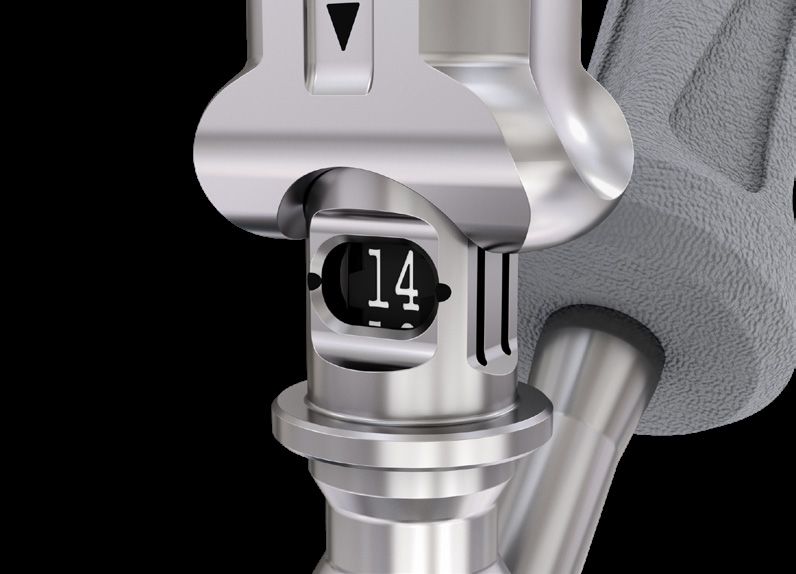
Surgical Technique

Step 4
                                                                                                Fig. 7
Tap

All SYMPHONY OCT System Screws have a fully threaded,
tapered tip. Taps are provided with an intended
interference (see Table 1). The SYMPHONY OCT System
Screws have 2 different, anatomically designed thread
forms. Each of these thread forms requires a different
tap. Cortical Fix thread screws utilize gold colored taps,
while standard dual-lead thread screws utilize steel
colored taps, as shown in the picture below. Select the
correct tap to correspond with the chosen screw as
shown below in Table 1.

In cases of hard bone, sequential tapping may be utilized
by tapping progressively larger sizes until desired screw
size is reached. Care should be taken not to mix differing
thread forms, (see Table 1).
Note: Tapping is required on all screws.

Table 1

                            Screw /Tap Sizing                                                               Tap Size Interference

        ST                                                                    CFX                        Minor Thread Major Thread
                                   Cortical Fix Thread Taps and Standard
                                   Thread Taps are not interchangeable

    Screw Size   Standard Thread                                           Screw Size      CFX Thread     Diameter     Diameter
     3.0 mm       2020-33-330                                                  N/A              N/A       -0.15 mm       -0.13 mm

     3.5 mm       2020-33-335                                                  N/A              N/A       -0.15 mm        -0.2 mm

     4.0 mm       2020-33-340                                                  N/A        2020-33-540     -0.15 mm        -0.2 mm

     4.5 mm       2020-33-345                                                4.5 mm       2020-33-545     -0.15 mm        -0.2 mm

       N/A            N/A                                                    5.0 mm       2020-33-550     -0.15 mm        -0.2 mm

       N/A            N/A                                                    5.5 mm       2020-33-555     -0.15 mm        -0.2 mm

The Tap Sleeve may be used as a tissue protector and to
indicate tap depth. (Fig. 7)
Precautions:
• T
   he reported depth of the Tap Sleeve may be more
  shallow than actual due to interference on bony
  anatomy and soft tissue. Verfication of actual
  depth using depth gauge is recommended.
• T
   aps for Standard and CFX threadforms are not
  interchangeable. Taps are designed to undertap by
  default (see Table 1).

8     DePuy Synthes SYMPHONY™ OCT System                                   Surgical Technique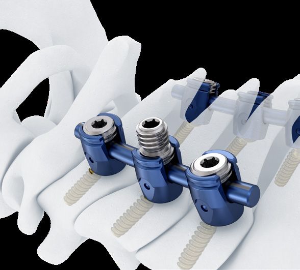
Surgical Technique
Step 5 Fig. 8
Insert Screws
Polyaxial Screw Driver Shaft X20 2020-33-400
Polyaxial Screw Driver Retention Sleeve 2020-00-401
Polyaxial Screw Driver Tissue Sleeve 2020-00-410
Retract Slide
Sleeve Sleeve
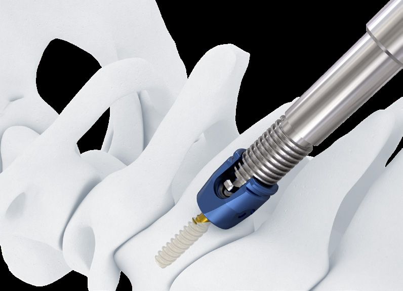
Always confirm screw length before insertion. (Fig. 8) Load
screw
shaft to
Attach screwdriver to polyaxial screw. (Fig. 9) driver tip Advance
Fig. 9 Push sleeve and
(1). Ensure that the Retention Sleeve is retracted by Release thread into
Button Screw
pushing down the release mechanism and sliding back.
(2). Insert
the tip of the Polyaxial Screw Driver Shaft X20
into the drive feature of the polyaxial screw.
(3). S lide the Polyaxial Screw Driver Retention Sleeve until it
comes in contact with the body of the polyaxial screw.
Rotate the sleeve clockwise until it bottoms out on the
cross pin of the screwdriver shaft. 1 2 3
The polyaxial screw is ready for bone insertion.
Fig. 10
Screw can also be loaded from directly inside the
caddy.
Remove screwdriver from the polyaxial screw by turning
the knob counterclockwise. (Fig. 10, 11)
Precaution: Polyaxial Screw Driver Tissue Sleeve is
optional. If not using, be mindful that not allowing
rotation of the retention sleeve during insertion can
lead to screw disengagement.
Fig. 11
SYMPHONY™ OCT System Surgical Technique DePuy Synthes 9Surgical Technique
Step 6
Fig. 12
Align Screw Heads and Perform Adjustments
Screw, Head and Rod Adjuster 2020-00-134
Utilize the Screw, Head and Rod Adjuster to align the
screw heads. If the screw is over tightened the head will
not rotate. In this situation, utilize the X20 end of the
Screw, Head and Rod Adjuster, to back the bone screw
out until polyaxial motion is achieved. (Fig. 12)
Step 7
Template the Rod
Rod Template 240 mm 388.868
If desired, contour the Rod Template 240 mm to fit the Fig. 13
anatomy. (Fig. 13)
11 DePuy Synthes SYMPHONY™ OCT System Surgical TechniqueSurgical Technique
Step 8
Fig. 14
Contour and Cut the Rod
Rod Cutter for 3.5 and 4.0 mm Rods 2020-00-135
Bending Iron Right 2020-00-146
Bending Iron Left 2020-00-147
French Rod Bender for 3.5 and 4.0 mm Rods 2020-00-145
Rod Introducer 2883-05-007
Fig. 15
If necessary, cut and bend the rod to match the template.
Pre-cut, Pre-Lordosed rods are also available.
Use the French Rod Bender for 3.5 and 4.0 mm Rods to
contour the rod to match the curve of the template. (Fig. 14)
The Bending Irons can also be used as pipe rod benders.
Insert the rod into the rear of each bending iron and lock Fig. 16
in place by turning the thumbwheels clockwise if desired.
(Fig. 15) As the rod is fed into the pipe, it will pass
through on the other side. (Fig. 15)
As the bent portion of the rod is fed through into the
frame of the benders, it can pass through the clearance
cut to allow further bending. (Fig. 16)
Fig. 17
Precaution: Repeated bending of rods may lead to
rod fracture.
Utilize open architecture to loosen
clamps if stuck. It is not intended for
tightening
SYMPHONY™ OCT System Surgical Technique DePuy Synthes 11Surgical Technique
Straight rods can be bent via the through holes marked for
either 3.5 or 4.0 mm rods. (Fig. 18, 20) Bent rods needing Fig. 18
adjustment can be cut using the open saw. (Fig. 19)
Precautions:
• C
are should be taken to secure the retained and
cut ends during cutting to prevent injury.
• K
eep fingers away from within the open span of
the Rod Cutters during use to avoid injury.
Fig. 19
• E
nsure rod is fully seated in cutting slot with each
use to avoid potential user harm.
Warning: Rod cutters are not intended to be used in
situ due to the risk of patient injury.
Fig. 20
Step 9
Place the Rod Fig. 21
Rod Introducer 2883-05-700
Insert the rod into the heads of the polyaxial screws using
the Rod Introducer. (Fig. 21)
11 DePuy Synthes SYMPHONY™ OCT System Surgical TechniqueSurgical Technique
Step 10
Fig. 22
Reduce the Rod
Reducer Kerrison 2020-00-140
Reducer Rocker Fork* 2020-00-139
Use the Reducer Kerrison to reduce the rod into the
polyaxial head of the screw. Place the reducer over the
rod and onto the polyaxial head until seated. (Fig. 22)
Squeeze the handle to engage and reduce the rod into Fig. 22a,b
the head of the screw. Set screws can be inserted
through the cannula with the X15 Self Retaining Set P O
Screw Inserter which is identifiable via three alignment
bosses, two of which are toward the distal tip. (Fig. 23)
Use the Reducer Rocker Fork by placing it onto the top of
the rod, with the legs below the screw side notches. Lever
the fork in a slow and controlled way until the rod is
seated into the polyaxial head. Proceed with set screw
insertion. (Fig. 24) Aligned Misaligned
Note: The Reducer Kerrison helps ensure the rod is Fig. 23 3 Alignment Boss 3
fully seated in the saddle before final tightening.
Precaution: Care should be taken to avoid using
excessive force during rod reduction steps that may 1 Alignment Boss 1
undermine bony purchase and result in screw 2 Alignment Boss 2
pullout.
Fig. 24
* Instrument does not come standard in Core Instrument Set
SYMPHONY™ OCT System Surgical Technique DePuy Synthes 11Surgical Technique
Step 11
Fig. 25
Insert Set Screws
X15 Self Retaining Set Screw Inserter 2020-00-407
Dual Sided Set Screw Inserter* 2020-00-402
Insert the set screws using the X15 Self Retaining Set
Screw Inserter or the Dual Sided Set Screw Inserter. Set
screws can be inserted through either the Counter Torque
or the Reducer Kerrison using the X15 Self Retaining Set
Screw inserter. (Fig. 25)
Step 12
Lock the Construct
Fig. 26
X15 Driver Final Tightener 2020-00-403
AO Handle, Torque Limiting 3.0 Nm 2020-00-504
Counter Torque 2020-00-138
Fully tighten all set screws with the X15 Driver Final
Tightener, the Counter Torque, and the AO Handle,
Torque Limiting 3.0 Nm. (Fig. 26)
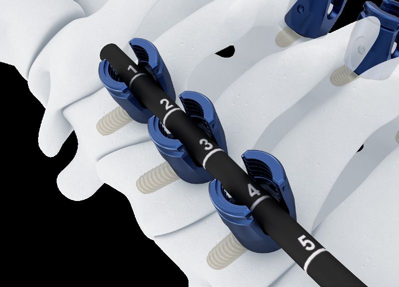
The construct is now rigidly locked. Final tightening
should be attempted only after all locking screws have
been placed. Tightening should be revisited to ensure all
levels are seated using a middle out tightening pattern, Recommended
alternating levels & rod locations. Ensure each screw is Tightening Order
final tightened. Now the construct is locked.
Precautions:
• T
he Screw Inserters are not intended for use in
final tightening. Damage to Set Screw Driver
5 4
feature may occur.
• A
lways fully reduce rod in all bone anchors prior
1 2
to final tightening.
• F
ailure to use provided 3.0Nm torque limiting
3 6
handle when final tightening may lead to set
screw back out.
* Instrument does not come standard in Core Instrument Set
11 DePuy Synthes SYMPHONY™ OCT System Surgical TechniqueOptional Surgical Techniques
Place Laminar Hooks
Fig. 27
Implant Holding Forceps* 03.614.030
The SYMPHONY OCT System is reverse compatible with
the existing SYNAPSE OCT System Hooks.
Attach Implant Holding Forceps to the appropriate hook.
Place the hook in the desired location using the X15 Self
Retaining Inserter as an aid. (Fig. 27, 28)
Fig. 28
* Instrument does not come in standard instrument set
SYMPHONY™ OCT System Surgical Technique DePuy Synthes 11Optional Surgical Technique
Apply Compression or Distraction
Fig. 29
Distraction Forceps 03.614.028
Compression Forceps 03.614.029
Compression and distraction can only be achieved if one of
the screws receiving the force is unlocked. Use the
Compression Forceps to achieve compression (Fig. 29), or
the Distraction Forceps to achieve distraction. (Fig. 30)
Fig. 30
Head to Head Cross Connector
Fig. 31
X15 Self Retaining Set Screw Inserter 2020-00-407
X15 Driver Final Tightener 2020-00-403
Rod Template 240 mm 388.868
Cross Connector Bender 2883-07-100
Nut Driver Self Retaining 2020-00-405
AO Handle, Torque Limiting 3.0 Nm 2020-00-504
Counter Torque 2020-00-138
Insert tall set screw through Counter Torque tube using
X15 Self Retaining Set Screw Inserter. Final tighten when
ready before implanting the H2H Cross Connector using
the AO Handle, Torque Limiting 3.0 Nm and Counter
Torque. (Fig. 31)
Warning: Failure to final tighten before implanting
Cross Connector may result in postoperative
loosening.
11 DePuy Synthes SYMPHONY™ OCT System Surgical TechniqueOptional Surgical Technique
After final tightening of all screws:
Fig. 32
a. Utilize the Rod Template 240 mm to measure the space
between the screws and choose an appropriate sized
Cross Connector. (Fig. 32)
b. Contour as needed, using the Cross Connector Fig. 33
Benders provided, ensuring eyelets are able to fully seat
on Tall Set Screw. (Fig. 33)
Precaution: Reverse bending of the plates should
not be attempted. Extreme bending over the rod
attachment body travel slot will limit the amount
of medial/lateral adjustment in the rod attachment
body.
Fig. 34
c. Place Cross Connector onto screw heads so the Tall Set
Screw extends through the Cross Connector. (Fig. 34)
Fig. 35
d. Select and load the Locking Nut to the Nut Driver Self
Retaining by aligning the driver with the flats of the
nut. (Fig. 35)
e. After all locking nuts have been placed, firmly tighten
them with the Nut Driver Self Retaining connected to Fig. 36, 37
the AO Handle, Torque Limiting 3.0 Nm. (Fig. 36)
Counter torquing is achieved by placing the Counter
Torque on the adjacent screw head on the same side of
the construct. (Fig. 37)
Precaution: Failure to use provided 3.0 Nm torque
limiting handle when final tightening may lead to
set screw back out.
SYMPHONY™ OCT System Surgical Technique DePuy Synthes 11Optional Surgical Technique
Head to Head Cross Connectors may also be used where
a screw is not present by using the Cross Connector Head Fig. 38
Adapter. The set screw must be fully tightened using an
adjacent level Counter Torque as shown in Figure 37 prior
to implanting any connectors. (Fig. 38)
Warning: Failure to final tighten before implanting
Cross Connector may result in postoperative
loosening.
Fig. 39
Removal of nut from driver
a
If at any time unloading of the Nut from the Nut Driver
Self Retaining is required, utilize the threaded post on
Caddy. Engage one or more threads and gently pull. Nut
is then removed from post by unthreading in a
counterclockwise direction. (Fig. 39a-c)
b
c
11 DePuy Synthes SYMPHONY™ OCT System Surgical TechniqueOptional Surgical Technique
Rod to Rod Cross Connector
Fig. 40
X15 Self Retaining Set Screw Inserter 2020-00-407
X15 Driver Final Tightener 2020-00-403
Rod Template 240 mm 388.868
AO Handle, Torque Limiting 3.0 Nm 2020-00-504
Rod to Rod Cross Connector Counter Torque 2020-00-163
Fig. 41
a. Place the Rod Template between the Screw Heads and
measure. Then choose the appropriate size Rod to Rod
Cross Connector. (Fig. 40)
b. The open jaws of the Rod to Rod Cross Connector Fig. 42
have a retaining feature and can be placed onto the
rod, it may require a gentle push to snap on. (Fig. 41,
42)
c. Assemble X15 Final Tightener, AO Handle Torque Fig. 43
Limiting 3.0 Nm, and Cross Connector Counter Torque. a
Insert Driver tip into set screw then lower Counter
Torque body over Cross Connector. Then, slide the
Counter Torque over the head of the set screw. Tighten
each end first and then the center using the AO
Handle, Torque Limiting 3.0 Nm. (Fig. 43a-c)
The two smallest sizes of Rod to Rod Cross Connector b
only have two set screws.
Precautions:
• A
lways use Rod to Rod Counter Torque when
tightening set screws as it facilitates alignment of
the set screw and reduces risk of disengagement.
c
• F
ailure to use provided 3.0 Nm torque limiting
handle when final tightening may lead to set
screw back out.
SYMPHONY™ OCT System Surgical Technique DePuy Synthes 11Optional Surgical Technique
Lateral Offset Connectors
Fig. 44
X15 Self Retaining Set Screw Inserter 2020-00-407
X15 Driver Final Tightener 2020-00-403
AO Handle, Torque Limiting 3.0 Nm 2020-00-504
Counter Torque 2020-00-138
Place the opening of the chosen Lateral Offset Connector
on the rod. (Fig. 44) Loosely tighten the connector to the
rod. Introduce the bar of the Lateral Offset Connector into Fig. 45
the polyaxial head of the screw. Insert the set screw using
X15 Inserter into the polyaxial head and lock into place.
Counter torquing is achieved by placing the Counter
Torque on the adjacent screw head on the same side of
the construct. (Fig. 45)
Tighten the set screw of the polyscrew using the X15 Final
Tightener Set Screw Inserter and AO Handle, Torque
Limiting 3.0 Nm. Fig. 46
Precaution: Failure to use provided 3.0 Nm torque
limiting handle when final tightening may lead to set
screw back out.
Parallel Connectors
X15 Self Retaining Set Screw Inserter 2020-00-407
X15 Driver Final Tightener 2020-00-403
AO Handle, Torque Limiting 3.0 Nm 2020-00-504
Parallel connectors allow adjacent coupling of two rods of
the same or differing diameters. The self-retaining feature
of the X15 Self Retaining Set Screw Inserter can aid with
insertion. Either side of the connector may be connected
first. Tighten the set screw on one side, then connect the
remaining rod and tighten the set screws using the X15
Driver, Final Tightener and the AO Handle, Torque Limiting
3.0 Nm. All set screws are designed to be flush or recessed
from the top of the implant when locked. (Fig. 46)
Precaution: Failure to use provided 3.0 Nm torque
limiting handle when final tightening may lead to set
screw back out.
22 DePuy Synthes SYMPHONY™ OCT System Surgical TechniqueOptional Surgical Technique
Axial Connectors
Fig. 47
X15 Self Retaining Set Screw Inserter 2020-00-407
X15 Driver Final Tightener 2020-00-403
AO Handle, Torque Limiting 3.0 Nm 2020-00-504
1
Counter Torque 2020-00-138
Insert contoured rods into axial connector and final tighten
using the AO Handle, Torque Limiting 3.0 Nm. This can be
2
done prior to rod insertion in connectors or in vivo using the
following technique:
1. Insert Axial Connector onto smaller rod first.
2. Slide Axial Connector onto second rod until both rod ends
are visible in window. (per Fig. 47)
3. Tighten Axial Connector using the AO Handle, Torque
Limiting 3.0 Nm and apply Counter Torque by placing the
Counter Torque over the rod closest to each set screw
during final tightening.
Precaution: Failure to use provided 3.0 Nm torque
limiting handle when final tightening may lead to set
screw back out.
SYMPHONY™ OCT System Surgical Technique DePuy Synthes 22Optional Surgical Technique
Cable Connector
Fig. 48
X15 Self Retaining Set Screw Inserter 2020-00-407
X15 Driver Final Tightener 2020-00-403
AO Handle, Torque Limiting 3.0 Nm 2020-00-504
Cable Connector can be added to rod using X15 Self
Retaining Set Screw Inserter.
Cabling technique is detailed in the DePuy Synthes Spine
Songer Cable Technique Guide. (Fig. 48)
Precaution: Failure to use provided 3.0 Nm torque
limiting handle when final tightening may lead to set
screw back out.
22 DePuy Synthes SYMPHONY™ OCT System Surgical TechniqueOptional Surgical Technique
Implant Removal Instructions:
If the decision is made to remove implants the following
steps should be taken after the implant is exposed.
For set screw and rod, clean debris from set screw and
lower the Counter Torque over the screw head. Insert the
X15 into the Counter Torque and engage the set screw.
Turn handle counterclockwise to loosen the set screws.
Once the set screws are removed the rods can then be
removed.
All SYMPHONY OCT System Bone Screws can be removed
with an X20 screwdriver. Once the rods are removed,
align the polyaxial head to allow access to drive feature
and engage the X20. Turn counterclockwise to remove
the screw.
All other implants are removed using an X15 screwdriver.
Certain connectors require the use of the Nut Driver for
removal.
SYMPHONY™ OCT System Surgical Technique DePuy Synthes 22Optional Surgical Technique
Compatibility
The SYMPHONY OCT System has been designed to be compatible with specific DePuy Synthes Spine Occipital
Cervical Fusion Systems as well as specific Thoracolumbar Systems.
SYMPHONY OCT System Compatibility Chart Compatible Not Compatible
DePuy Synthes Spine Cervico-Thoracic Screw-Rod Systems
SYNAPSE OCT System Instruments Compatible with specific
instruments. See p. 25
SYNAPSE OCT System Rod and Hook Implants X
SYNAPSE OCT System Screw Implants X
MOUNTAINEER OCT System Instruments X
MOUNTAINEER OCT System Screw and Rod Implants X
AXON™ Pedicle Screw System Instruments and Implants X
®
SUMMIT SI OCT Spinal Fixation System Instruments
X
and Implants
DePuy Synthes Spine OC Fusion Systems
SYNAPSE OCT System - OC Fusion Except for Top Loading
Instruments and Implants Occipital Fusion Connectors
MOUNTAINEER OCT System - OC Fusion Instruments
X
and Implants
DePuy Synthes Spine Posterior Thoracolumbar Screw and Rod Systems
EXPEDIUM® 5.5 Spine System X
EXPEDIUM 6.35 Spine System X
EXPEDIUM 4.5 Spine System X
®
EXPEDIUM VERSE System X Via the use
of Transition
VIPER® 2 System X
Rods and
®
VIPER Cortical Fix Fenestrated Screw System X Connectors
VIPER PRIME™ System X
MATRIX Spine System X
USS™ Spinal System X
22 DePuy Synthes SYMPHONY™ OCT System Surgical TechniqueOptional Surgical Technique
SYNAPSE OCT System Compatibility
The SYMPHONY OCT System has been designed to be compatible with specific SYNAPSE OCT System Instruments.
The following instruments are compatible to be used with SYMPHONY OCT System Implants. These instruments are
provided as part of the SYNAPSE OCT System and are designed for storage within the SYNAPSE-to-SYMPHONY
Upgrade Set. For usage instructions please refer to the SYNAPSE OCT System Surgical Technique.
SYNAPSE OCT
System Code Description Step Notes
388.397 Awl Start screw hole
388.394 2.4 mm Drill Bit/QC with 65 mm Stop Prepare screw pathway
2020-00-155 2.8 mm Drill for Synapse Upgrade Prepare screw pathway
03.614.010 3.2 mm Drill Bit with 65 mm Stop QC Prepare screw pathway
388.393 Drill Guide with Graduation for 2.4 mm Prepare screw pathway
Drill Bit
03.614.011 Drill Guide with Graduation for 3.2 mm Prepare screw pathway
Drill Bit
03.614.012 Pedicle Probe 2.4 mm Prepare screw pathway For inserting screws 4.5, 5.0, 5.5,
3.2 mm probes should be used
03.614.013 Curved Pedicle Probe 2.4 mm Prepare screw pathway For inserting screws 4.5, 5.0, 5.5,
3.2 mm probes should be used
03.161.028 Depth Gauge Confirm depth and pathway
388.549 Straight Ball Tip Probe-Small Confirm depth and pathway
03.614.036 Slip Sleeve for Threaded Holding Sleeve Insert screws
03.614.017 Threaded Holding Sleeve for Insert screws
Polyaxial Screws
03.614.034 Alignment Tool Align screw heads and
perform adjustments
03.614.022 Rod/Plate Bender Contour and cut the rod
03.614.024 Bending Iron-Left Contour and cut the rod
03.614.025 Bending Iron-Right Contour and cut the rod
03.614.021 Rod Cutter Contour and cut the rod SYNAPSE Rod Cutter not designed to
cut Cobalt Chrome Rod
03.615.011* Table Top Rod Cutter Contour and cut the rod
388.407 Holding Forceps Place the rod
03.614.027 Persuader Reduce the rod
324.107 Quick Coupling Handle with Swivel Cap Various
03.688.505* Ratchet Handle with Sports Grip Various
03.614.041* Ratchet Handle with T-Handle Various
* Not housed in the Synapse-to-Symphony Upgrade Set
SYMPHONY™ OCT System Surgical Technique DePuy Synthes 22Optional Surgical Technique
Not Compatible
The following instruments from the SYNAPSE OCT System are NOT COMPATIBLE with the SYMPHONY OCT System:
SYNAPSE OCT
System Code Description Product Type
03.614.026 Counter Torque for 3.5 mm Rods Counter Torque
03.615.010 Counter Torque for 4.0 mm Rods Counter Torque
03.615.016 Rocker Fork for 4.0 mm Rods Reducer
03.615.009 Persuader for 4.0 mm Rods Reducer
03.614.052 Undersized tap for 3.5 mm Cancellous Screws Tap
03.614.053 Undersized tap for 4.5 mm Cancellous Screws Tap
03.614.045 Short tap for 3.5 mm Cancellous Bone
Tap
Screws with Sharp Tip
03.614.046 Short Tap for 4.5 mm Cancellous Bone
Tap
Screws with Sharp Tip
311.349 Tap for 3.5 mm Cancellous Bone Screws Tap
389.477 Tap for 3.5 mm Cortex Screws Tap
03.614.035 2 Nm Torque Limiting Handle, with Quick Coupling Torque Limiting Handle
03.614.018 Cross Pinned Star Drive Screw Driver Shaft, T15,
Bone Screw Driver
Self-retaining, Quick Coupling
03.614.039 Cross Pinned Hexagonal Screw Driver Shaft,
Bone Screw Driver
Quick Coupling
03.614.019 Star Drive Screw Driver Shaft, T15, Self-Retaining,
Set Screw Driver
Quick Coupling
03.614.050 Dual Sided Locking Cap Inserter Set Screw Driver
03.614.048 T15 Shaft for Torque Limiting Nut Driver Set Screw Driver
22 DePuy Synthes SYMPHONY™ OCT System Surgical TechniqueOccipital Cervical Fusion
SYNAPSE OCT System
The DePuy Synthes Spine SYMPHONY OCT System is
compatible with additionally available implants and
instruments that are intended to provide immobilization
and stabilization as an adjunct to fusion of the
occipitocervical junction. The OC Fusion System includes a
complete set of implants and instruments designed to
optimize fixation to the occiput and connect with DePuy
Synthes Spine Cervical and Thoracic Systems.
Features
The OC Fusion System offers the surgeon several implant
options for the occiput. The instrumentation is designed
to accommodate mid-line exposures and varying patient
anatomy.
SYMPHONY™ OCT System Surgical Technique DePuy Synthes 22Occipital Cervical Fusion Preoperative Planning 1 Imaging All necessary imaging studies should be available to plan occipital screw placement and accommodate anatomic variations in individual patient anatomy. 2 Position Patient Patient positioning is critical for occipitocervical fusion procedures. The patient should be placed on the operating table in the prone position with the patient’s head securely immobilized. Confirm proper patient position by direct visualization and reconciliation with radiographs before draping. 3 Approach Make a standard midline incision from the external occipital protuberance and continue caudally, and then expose the posterior bony elements sufficiently to allow placement of instrumentation as well as preferred graft material in and around the decorticated posterior elements. 22 DePuy Synthes SYMPHONY™ OCT System Surgical Technique
Occipital Cervical Fusion

Step 1
Attach Bone Anchors

Attach bone anchors to the cervical and/or thoracic spine
as described in the DePuy Synthes Spine SYMPHONY OCT
System as needed.

Step 2
                                                                                Fig. 49
Select Occipital Plate

 03.161.0xx           Template, for Occipital Plate
 387.689              Plate Holder

Select a template of the plate style and size estimated to
best fit the occiput. Contour the template to fit the
anatomy. (Fig. 49)

Step 3
Contour Plate
                                                                                Fig. 50
 03.161.042           Plate Bender

Use the Plate Bender to contour the plate to fit the
anatomy. Use the template as a guide. The Plate Bender
can be used across any section of the plate, including the
area lateral to the rod attachment bodies. (Fig. 50)

Precaution: Reverse bending of the plates should not
be attempted. Bending over the rod attachment body
travel slot may limit the amount of medial/lateral
adjustment in the rod attachment body.

Alternative Instrument
                                                                                Fig. 51
 391.88               Locking Pliers

Locking Pliers can be also used to create bends. (Fig. 51)

Precaution: Reverse bending of the plates should not
be attempted. Extreme bending over the rod
attachment body travel slot will limit the amount of
medial/lateral adjustment in the rod attachment
body.

                                                             SYMPHONY™ OCT System Surgical Technique   DePuy Synthes   22
Occipital Cervical Fusion
Step 4
Fig. 52
Set Drill Guide Depth
03.161.023 Adjustable Drill Guide
Set the Adjustable Drill Guide to the desired depth. Slide
back the latch to release the inner tube. Align the
indicator of the inner tube with the appropriate depth
calibration on the outer tube. Release the latch to lock
the Adjustable Drill Guide at the desired depth. (Fig. 52)
Step 5 Fig. 53
Drill
03.161.023 Adjustable Drill Guide
03.161.024 3.2 mm Drill Bit
387.689 Plate Holder
Drill hole along the desired trajectory to the required
depth, using the 3.2 mm Drill Bit through the Adjustable
Drill Guide. Drilling must occur through the occipital plate
to ensure proper drilling depth. (Fig. 53, 54) Fig. 54
Warning: Do not actuate latch when drilling. This
could disengage the lock and result in uncontrolled
depth and resulting in patient harm.
Alternative Instrument
03.161.105* 3.2 mm Drill Bit with Flexible Shaft
Step 6
Measure Fig. 55
03.161.028 Depth Gauge
Use the Depth Gauge to confirm hole depth and select
the corresponding screw length. The Depth Gauge
reading and the screw length indicate actual bone
purchase. The Depth Gauge must sit directly on the bone.
(Fig. 55)
* Instrument does not come standard in OC Fusion Set
33 DePuy Synthes SYMPHONY™ OCT System Surgical TechniqueOccipital Cervical Fusion
Step 7
Fig. 56
Tap
03.161.023 Adjustable Drill Guide
03.161.026 Tap for 4.5 mm Occipital Screws
Tap through the Adjustable Drill Guide and occipital
plate, to ensure proper tapping depth. (Fig. 56)
Note: Tapping is required for all screws.
Warning: Do not actuate latch when tapping. This
could disengage the lock, and result in uncontrolled
depth and resulting in patient harm.
Alternative Technique
Fig. 57
03.161.023 Adjustable Drill Guide
03.161.027 Universal Joint Tap for 4.5 mm
Occipital Screws
Set the tap depth by turning the tap sleeve to the desired
depth. Lock the tap sleeve by turning down the locking
nut to contact the tap sleeve. Finger tighten the locking
nut. Use the Holding Forceps to provide axial force and
stability. Tapping must occur through the occipital plate
to ensure proper tapping depth. (Fig. 57)
Warning: Do not touch the latch when tapping.
Touching the latch could disengage the lock resulting
in uncontrolled depth and potential harm to the
patient.
SYMPHONY™ OCT System Surgical Technique DePuy Synthes 33Occipital Cervical Fusion
Step 8
Fig. 58
Insert Screw
388.392 Stardrive, Locking Screwdriver Shaft, T15
Insert the selected 4.5 mm occipital screw and tighten
using the Stardrive, Locking Screwdriver Shaft, T15.
(Fig. 58)
Precaution: A 5.0 mm screw is available if the
primary screw has unsatisfactory fixation.
Fig. 59
Alternative Technique
03.161.031 Universal Joint Screwdriver, T15
388.407 Holding Forceps
Use the universal joint screwdriver to insert the selected
screw. Use the Holding Forceps to provide axial force and
stability. (Fig. 59)
Step 9 Fig. 60
Insert Additional Screws
Insert remaining screws, per steps 4–8. (Fig. 60)
Step 10
Contour Rod Template
388.868 Rod Template, 240 mm
Fig. 61
Contour the Rod Template, 240 mm to fit the anatomy
and to seat fully in the cervical and upper thoracic bone
anchors. Create the occipitocervical bend and ensure
sufficient rod length to connect with the occipital plate.
(Fig. 61)
33 DePuy Synthes SYMPHONY™ OCT System Surgical TechniqueOccipital Cervical Fusion
Step 11
Fig. 62
Bend and Cut Rod
French Rod Bender for 3.5 and 4.0 mm Rods 2020-00-145
Rod Cutter for 3.5 and 4.0 mm Rods 2020-00-135
Use the Rod Cutter to cut the rod to the appropriate length. Contour the
3.5 mm or 4.0 mm rod to match the template. (Fig. 62)
Precautions:
• C
are should be taken to secure the retained and cut ends during
cutting to prevent injury.
• R
epeated bending may weaken the rod and lead to rod fracture.
• K
eep fingers away from within the open span of the Rod Cutters
during use to avoid injury.
• E
nsure rod is fully seated in cutting slot with each use to avoid
potential user harm.
Warning: Rod cutters are not intended to be used in situ due to the
risk of patient injury.
SYMPHONY™ OCT System Surgical Technique DePuy Synthes 33Occipital Cervical Fusion
Step 12
Fig. 63
Attach Rods
03.161.041 Positioning Tool
03.615.007 Positioning Tool, for 4.0mm Rods
388.392 Stardrive, Locking Screwdriver Shaft, T15
Insert rods into the rod attachment body. Ensure that the
rods extend slightly past the end of the plate. Use the
locking screwdriver shaft to insert the titanium locking Fig. 64
screw. Use the Positioning Tool to facilitate rod placement
and locking screw insertion. (Fig. 63)
Alternatively, the Universal Joint Screwdriver and Holding
Forceps may also be used to insert the titanium locking
screw. (Fig. 64)
Final Tightening
Fig. 65
388.392 Stardrive, Locking Screwdriver Shaft, T15
Use the Stardrive, Locking Screwdriver Shaft, T15 for final
tightening of all occipital screws and locking screws.
(Fig. 65)
Note:
nsure the correct set screw is used to match the
E
correct Occipital Plate.
• O
C Fusion Plate (Gold) for 4.0 mm Rod takes:
04.614.508
04.614.508
• O
C Fusion Plate (Green) for 3.5 mm Rod takes:
406.104
406.104
33 DePuy Synthes SYMPHONY™ OCT System Surgical TechniqueOccipital Cervical Fusion
Occipital Clamps
Step 1
Attach Bone Anchors
Attach bone anchors to the cervical and thoracic spine as described in
the DePuy Synthes Spine SYMPHONY OCT System.
Step 2
Contour Rod Template
388.868 Rod Template, 240 mm
Fig. 66
Contour the Rod Template to fit the anatomy and to seat fully in the
cervical and upper thoracic bone anchors. Create the occipitocervical
bend and ensure sufficient rod length to connect with the occipital
clamp. (Fig. 66)
Step 3
Cut and Bend Rod
Rod Cutter for 3.5 and 4.0 mm Rods 2020-00-135
French Rod Bender for 3.5 and 4.0 mm Rods 2020-00-145 Fig. 67
Use the Rod Cutter to cut the rod to the appropriate length. Contour
the 3.5 mm or 4.0 mm rod to match the template. (Fig. 67)
Precautions:
• C
are should be taken to secure the retained and cut ends
during cutting to prevent injury.
• R
epeated bending may weaken the rod and lead to rod
fracture.
Fig. 68
• K
eep fingers away from within the open span of the Rod
Cutters during use to avoid injury.
• E
nsure rod is fully seated in cutting slot with each use to
avoid potential user harm.
Warning: Rod cutters are not intended to be used in situ due to
the risk of patient injury.
Step 4
Place First Clamp on Rod
388.392 Stardrive, Locking Screwdriver Shaft, T15
Place the occipital clamp on the titanium rod and tighten the set screw
in the clamp to engage the rod, thus facilitating placement. Do not
firmly tighten as it must be able to be positioned on bone. (Fig. 68)
SYMPHONY™ OCT System Surgical Technique DePuy Synthes 33Occipital Cervical Fusion
Step 5
Fig. 69
Set Drill Guide Depth
03.161.023 Adjustable Drill Guide
Set the Adjustable Drill Guide to the desired depth. Slide
the latch to release the inner tube. Align the indicator of
the inner tube to the desired depth on the outer tube.
Release the latch to lock. (Fig. 69)
Step 6 Adjustment Image
Drill Fig. 70
03.161.023 Adjustable Drill Guide
03.161.024 3.2 mm Drill Bit
388.407 Holding Forceps
03.161.105 3.2 mm Drill Bit with Flexible Shaft
To hold the rod in position use the Holding Forceps. Drill
to the desired trajectory and depth using the 3.2 mm Drill
Drilling Image
Bit through the Adjustable Drill Guide. Drill to the stop.
Drilling must occur through the occipital plate to ensure
proper drilling depth. (Fig. 70)
Warning: Do not touch the latch when drilling.
Touching the latch could disengage the lock,
resulting in uncontrolled depth and potential harm
to the patient.
Alternatively, the 3.2 mm Drill Bit with Flexible Shaft may
be used for drilling.
Fig. 71
Step 7
Measure
3.161.028 Depth Gauge
Use the depth gauge to confirm hole depth and screw
selection. The Depth Gauge must sit directly on the bone.
(Fig. 71)
33 DePuy Synthes SYMPHONY™ OCT System Surgical TechniqueOccipital Cervical Fusion
Step 8
Fig. 72
Tap
03.161.023 Adjustable Drill Guide
03.161.026 Tap for 4.5 mm Occipital Screws
To ensure proper tapping depth, tap through the
Adjustable Drill Guide and occipital plate. (Fig. 72)
Note: Tapping is required for all screws.
Warning: Do not actuate latch when tapping or
drilling. This could disengage the lock, and result in
uncontrolled depth and resulting in patient harm.
Alternative Technique
03.161.027 Universal Joint Tap for 4.5 mm
Occipital Screws Fig. 73
388.407 Holding Forceps
Tapping must occur through the occipital plate to ensure
proper tapping depth. Set the desired tap depth by
turning the tap sleeve. Lock the tap sleeve by turning the
locking nut until finger tight. Use the Holding Forceps to
provide stability. (Fig. 73)
Warning: Do not actuate latch when tapping. This
could disengage the lock, and result in uncontrolled
depth and resulting in patient harm.
SYMPHONY™ OCT System Surgical Technique DePuy Synthes 33Occipital Cervical Fusion
Step 9
Fig. 74
Insert Screw
388.392 Stardrive, Locking Screwdriver Shaft, T15
Insert the selected 4.5 mm occipital screw and tighten. (Fig. 74)
Note: A 5.0 mm screw is available if the
primary screw has unsatisfactory fixation.
Alternative Technique
Fig. 75
03.161.031 Universal Joint Screwdriver, T15
388.407 Holding Forceps
Use the Universal Joint Screwdriver, T15 to insert the selected
screw. Use the Holding Forceps to provide axial force and
stability. (Fig. 75)
Step 10
Insert Additional Screws and Clamps
Fig. 76
Insert remaining screws and clamps as in steps 4-9. A minimum
of 2 clamps per rod is required. (Fig. 76)
Precaution: A minimum of 2 clamps per rod is required.
Step 11
Final Tightening
388.392 Stardrive, Locking Screwdriver Shaft, T15
Fig. 77
Use the locking screwdriver shaft for final tightening of all
occipital screws and clamp set screws. (Fig. 77)
The Universal Joint Screwdriver, T15 and Holding Forceps may
also be used for final tightening.
Precaution: Always use Counter Torque using adjacent
level method to avoid transmission of tightening forces to
patient. Failure to do so could result in loss of correction.
33 DePuy Synthes SYMPHONY™ OCT System Surgical TechniqueOccipital Cervical Fusion
Occipital Plate Rod
Step 1
Attach Bone Anchors
Attach bone anchors to the cervical and thoracic spine as described in
the DePuy Synthes Spine SYMPHONY OCT System.
Step 2
Contour Rod Template
03.161.003 Template for Occipital Plate/Rod
Fig. 78
Contour the Template for Occipital Plate/Rod to fit the anatomy and to
seat fully in the cervical and upper thoracic bone anchors. (Fig. 78)
Step 3
Cut and Bend Rod
2020-00-135 Rod Cutter for 3.5 and 4.0 mm Rods
2020-00-145 French Rod Bender for 3.5 and 4.0 mm Rods
Contour the 3.5 mm or 4.0 mm rod to match the template. Use the
Rod Cutter to cut the rod to the appropriate length.
Precautions:
• C
are should be taken to secure the retained and cut ends
during cutting to prevent injury.
• K
eep fingers away from within the open span of the Rod
Cutters during use to avoid injury
• E
nsure rod is fully seated in cutting slot with each use to
avoid potential user harm
• R
epeated bending may weaken the rod and lead to rod
fracture.
Warning: Rod cutters are not intended to be used in situ due to
the risk of patient injury.
Step 4
Set Drill Guide Depth
03.161.023 Adjustable Drill Guide
Set the Adjustable Drill Guide to the desired depth by sliding back the
latch to release the inner tube. Align the indicator of the inner tube
with the appropriate depth marking on the outer tube. Release the
latch to lock the drill guide.
SYMPHONY™ OCT System Surgical Technique DePuy Synthes 33Occipital Cervical Fusion Step 5 Drill Fig. 79 03.161.023 Adjustable Drill Guide 03.161.024 3.2 mm Drill Bit 388.407 Holding Forceps 03.161.105 3.2 mm Drill Bit with Flexible Shaft Drill hole along the desired trajectory to the required depth, using the 3.2 mm Drill Bit through the Adjustable Drill Guide. Drilling must occur through the occipital plate to ensure proper drilling depth. (Fig. 79) Warning: Do not actuate latch when drilling. This could disengage the lock, and result in uncontrolled depth and resulting in patient harm. Alternatively, the 3.2 mm Drill Bit with Flexible Shaft may be used for drilling. Fig. 80 Step 6 Measure 03.161.028 Depth Gauge Use the Depth Gauge to confirm hole depth and screw selection. The Depth Gauge must sit directly on the bone. (Fig. 80) 44 DePuy Synthes SYMPHONY™ OCT System Surgical Technique
Occipital Cervical Fusion

Step 7
Tap                                                                         Fig. 81

 03.161.023      Adjustable Drill Guide
 03.161.026      Tap for 4.5 mm Occipital Screws

To ensure proper tapping depth, tap through the
Adjustable Drill Guide and occipital plate. (Fig. 81)

Precaution: Tapping is required for all screws.

Warning: Do not actuate latch when tapping. This
could disengage the lock, and result in uncontrolled
depth and resulting in patient harm.

Alternative Technique

 03.161.027      Universal Joint Tap for 4.5 mm                             Fig. 82
                 Occipital Screws
 388.407         Holding Forceps

Tapping must occur through the occipital plate to ensure
proper tapping depth. Set the desired tap depth by
turning the tap sleeve. Lock the tap sleeve by turning the
locking nut until finger tight. Use the Holding Forceps to
provide stability. (Fig. 82)

Warning: Do not actuate latch when tapping. This
could disengage the lock, and result in uncontrolled
depth and resulting in patient harm.

                                                         SYMPHONY™ OCT System Surgical Technique   DePuy Synthes   44
Occipital Cervical Fusion
Step 8
Fig. 83
Insert Screw
388.392 Stardrive, Locking Screwdriver Shaft, T15
Insert the selected 4.5 mm occipital screw and tighten.
(Fig. 83)
Note: A 5.0 mm screw is available if the
primary screw has unsatisfactory fixation.
Alternative Technique Fig. 84
03.161.031 Universal Joint Screwdriver, T15
388.407 Holding Forceps
Use the Universal Joint Screwdriver, T15 to insert the
selected screw. Use the Holding Forceps to provide axial
force and stability. (Fig. 84)
Step 9
Fig. 85
Insert Additional Screws
Insert remaining screws as previously described in steps
4–8. A minimum of 3 screws per Plate/Rod is required.
(Fig. 85, 86)
Fig. 86
44 DePuy Synthes SYMPHONY™ OCT System Surgical TechniqueOccipital Cervical Fusion
MOUNTAINEER OCT Spinal System
Fusion Technique
The MOUNTAINEER OC Fusion Set is offered as a stand
alone add-on to the SYMPHONY OCT System.
Fig. 87
The MOUNTAINEER OCT Spinal System offers an OC Plate
for occipital fixation. The OC Plate is available in three
sizes (Small – 31 mm, Medium – 37 mm, and Large – 45
mm) maximizing versatility in the medial-lateral position
of the rods. Each OC Plate size has three midline holes for
occipital fixation and two lateral arms with sliding and ro-
tating connection points for the rods.
The Large OC Plate (45 mm) offers two lateral holes for
additional fixation. (Fig. 87)
Step 1
Attach Bone Anchors
Attach bone anchors to the cervical and thoracic spine as
described in the DePuy Synthes Spine SYMPHONY OCT
System and SYNAPSE OCT System Technique Guides.
Step 2
Select Occipital Plate
Optimal OC Plate size is determined by measuring the
distance between the two longitudinal rods at the
occiput.
Distance Between Rods (mm)
Small Medium Large
OC Plate 31 mm 37 mm 45 mm
(+/- 4 mm) (+/- 4 mm) (+/- 4 mm)
SYMPHONY™ OCT System Surgical Technique DePuy Synthes 44Occipital Cervical Fusion
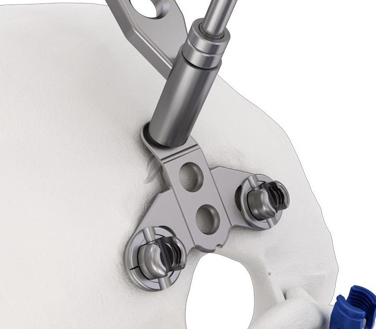
Step 3
Fig. 88
Plate Placement
2865-06-000 OC Plate Holder
Identify the external occipital protuberance (EOP) and the
posterior border of the foramen magnum. Utilizing the
OC Plate Holder, grasp the OC Plate and position it in the
midline between the EOP and the foramen magnum. (Fig. 88)
The OC Plate can be oriented with the single limb of the
implant cephalad in the midline and below the EOP or with Fig. 89,
the V portion of the implant cephalad in the midline and Fig. 90
below the EOP (Fig. 89, 90). The two limbs of the OC Plate
can be placed above the foramen magnum allowing for a
generous bone graft caudal to the implant.
Note: The OC Plate can be fixed to the occiput first or
to the rods then fixed to the occiput.
Step 4 Fig. 91
Contour OC Plate
2883-13-000 OC Plate Bender
The OC Plate should lay smoothly against the occiput. It
may be necessary to smooth irregular bony protuberances
slightly to optimize the bone to OC Plate interface, but
avoid removing significant portions of cortical bone
especially in the vicinity of planned screw holes. Fig. 92 front back
bend
zones
To contour the OC Plate, place it securely in the bender
and gently bend to desired radius. The contouring should
be performed only in the bend zones to avoid damage to
the sliding connectors. The OC Plate can be bent to a
maximum of 15° in either direction. (Fig. 91, 92, 93)
15°
The top tab of the OC plate may also be contoured as
shown. Fig. 93
Precaution: Reverse bending of the plates should not
be attempted. Extreme bending over the rod
attachment body travel slot will limit the amount of
medial/lateral adjustment in the rod attachment body.
To maintain the integrity of the occipital implant, the
OC Plate must be bent in one direction only.
44 DePuy Synthes SYMPHONY™ OCT System Surgical TechniqueOccipital Cervical Fusion
Optional Technique
Add Lateral Fixation Washer Fig. 94
The Lateral Fixation Washer with the OC Plate: The Lateral
Fixation Washer provides two additional lateral fixation points.
The Lateral Fixation Washer connects to the OC Plate with a
sliding dovetail connection. When using the Lateral Fixation
Washer assemble the washer to the OC Plate first, then select
the appropriate Occipital Fixed Depth Drill Guide. (Fig. 94)
Step 5
Drill
Fig. 95
2883-10-306 OC Drill Guide 6/8 mm
2883-10-310 OC Drill Guide 10/12 mm
2883-10-314 OC Drill Guide 14/16 mm
2883-10-035 OC 3.5 mm Drill
Select the appropriate Occipital Fixed Depth Drill Guide. With
the OC Plate in position, insert the Fixed Depth Drill Guide into
the superior midline hole of the OC Plate. Utilizing the 3.5 mm
Drill Bit, drill the initial occipital hole through the plate (and OC
Washer, if used). For more challenging anatomy a Flexible Shaft
Drill is alternatively available. (Fig. 95)
If drilling the initial occipital pilot hole directly to bone instead of
through the OC Plate, increase the screw length by 2 mm to
allow for the OC Plate and washer width (example: when
drilling 10 mm deep, select a 12 mm screw).
Note: 5.25 mm bone screws, with a self-tapping feature,
are also available. Use 4.5 mm bone screws first and
reserve the 5.25 mm bone screws for revision purposes.
Warning: The midline ridge of bone is shaped like a keel,
and it is possible to penetrate the inner cortex on one side
of the ridge and still be unicortical in the midline. The
occipital sinus is located in the midline and drains into
the transverse sinus. The consequences of penetrating this
small sinus potentially include thrombosis and
hemorrhage.
SYMPHONY™ OCT System Surgical Technique DePuy Synthes 44Occipital Cervical Fusion
Step 6
Confirm Depth Fig. 96
2883-03-000 Depth Gauge with Ball Tip
Always confirm drilling depth with the Depth Gauge. (Fig. 96)
Step 7
Tap
2883-10-3XX OC Drill Guide XX/XXmm
2883-10-045 OC 4.5 mm Tap
The pilot hole is then tapped with a 4.5 mm Tap.
Optional Instrument Fig. 97
2883-11-045 OC 4.5 mm Universal Joint Tap
For difficult anatomy, a Minimal Access Tap with a universal joint is available.
(Fig. 97)
Precaution: Use the same fixed depth drill guide as used to drill the
pilot hole. Stop tapping the hole before the tap “bottoms out” on the
drill guide to avoid stripping the bone threads.
Step 8
Insert Screw
2883-12-300* OC Straight Driver
Fig. 98
2883-12-000 OC Universal Joint Screwdriver
2883-14-200* Minimal Access OC Driver
Utilizing the 2.5 mm Self Retaining Screwdriver, insert the selected
4.5 mm Outer Diameter Occipital Bone Screw and tighten.
For difficult anatomy, a Minimal Access Self Retaining Screwdriver is available.
Do not fully tighten the bone screws until the construct has been fully
assembled. A small gap ventral to the OC Plate is helpful to allow the rod
connectors to slide within the OC Plate, which facilitates placement of the rods.
Insert the remaining Occipital Bone Screws in the same manner. Final tightening
is performed once the construct is fully assembled. (Fig. 98)
Occipital Bone Screws are removed with the 2.5 mm Self Retaining Screwdriver.
Note: 5.25 mm bone screws, with self-tapping feature are also available.
Use 4.5 mm bone screws first and reserve the 5.25 mm bone screws for
revision purposes.
*Instrument does not come in standard Mountaineer OC kit
44 DePuy Synthes SYMPHONY™ OCT System Surgical TechniqueOccipital Cervical Fusion
Step 9
Bend, Cut, and Place Rod
French Rod Bender for 3.5 and 4.0 mm Rods 2020-00-145
Rod Cutter for 3.5 and 4.0 mm Rods 2020-00-135
OC Tube Benders 2746-50-300
Rod Introducer 2883-05-700
Bending Iron Left 2020-00-147
Bending Iron Right 2020-00-146
AO Handle, Torque Limiting 3.0 Nm 2020-00-504
Polyaxial Screw Driver Shaft X20 2020-33-400
X15 Self Retaining Set Screw Inserter 2020-00-407
Cut and contour the rods so that they lay against the
posterior surface of the occipital plate and the proposed
final location of all polyaxial screw heads. The final length of
the rod should extend from the occipital fixation points
(approximately 10 mm caudal to the EOP) and 1-2 mm distal
to the first caudal fixation point. Care should be taken to
protect adjacent non instrumented levels.
SYMPHONY™ OCT System Surgical Technique DePuy Synthes 44Occipital Cervical Fusion
Step 9 continued
Fig. 99
Process Steps
To contour the rods, place the rod within the French Rod
Bender secure with forceps and gently contour until
desired radius is achieved. OC Tube Benders can be slid
over each end of the rod to provide additional contouring
for the OC junction. (Fig. 99)
Place contoured rods in the implant heads where possible
and secure with set screw.
Additionally, an Adjustable Rod is offered for use with the
SYMPHONY OCT System. When using the Adjustable
Rod, first adjust the angle of the joint to match the
patient anatomy and tighten the screw. For final
tightening use the AO Handle, Torque Limiting 3.0 Nm to
lock the joint.
Precautions:
• C
are should be taken to secure the retained and
cut ends during cutting to prevent injury.
• R
epeated bending may weaken the rod and lead to
rod fracture.
• K
eep fingers away from within the open span of
the Rod Cutters during use to avoid injury.
• E
nsure rod is fully seated in cutting slot with each
use to avoid potential user harm.
• F
ailure to use provided 3.0 Nm torque limiting
handle when final tightening may lead to set
screw back out.
• T
o avoid potential fatigue of the implant do not
make sharp bends or unbend the rod.
Warning: Rod cutters are not intended to be used in
situ due to the risk of patient injury.
44 DePuy Synthes SYMPHONY™ OCT System Surgical TechniqueOccipital Cervical Fusion
Step 10
Fig. 100
Construct Assembly
French Rod Bender for 3.5 and 4.0 mm Rods 2020-00-145
Rod Cutter for 3.5 and 4.0 mm Rods 2020-00-135
OC Tube Bender 2746-50-300
Confirm height and alignment of Polyaxial Screw Heads,
such that the slot within each screw head is directed in
line with the intended rod position.
Fig. 101
Place the rod in the Polyaxial Screw Heads and then into
the slots of the OC Plate. The sliding connectors in the
OC Plate should allow nearly parallel alignment of the
rods with minimal, if any, additional contouring required
in coronal plane. (Fig. 100)
The final length of the rod should extend from just cranial
to the OC Plate connection to the lowest level to be
instrumented taking care to preserve adjacent anatomy.
(Fig. 101)
Fig. 102
If additional contouring is required, secure the rod within
the French Rod Bender or the OC Tube Benders and gen-
tly contour until desired radius is achieved.
Step 11
Final Tightening
2883-14-000 OC Universal Joint Torque Driver
2883-14-100 OC Counter Torque Device
Perform final tightening of the Inner Set Screws on the
OC Plate by rotating the OC Universal Torque Driver
clockwise while providing counter torque on the rod with
the Counter Torque Device. The Inner Set Screw is
completely tightened when the Torque Driver clicks. OC
Plate Inner Set Screws are removed with the OC Universal
Torque Driver. (Fig. 102)
SYMPHONY™ OCT System Surgical Technique DePuy Synthes 44Drill Guide
Assembly
1. T hread scale body into Drill Guide 2. Push knob assembly down 3. Simultaneously push down and
Body until “A” symbol (“A” for until it is just over the rotate the knob to advance until
Assembly) appears in window. window. Ensure the “A” numbers indicating depth appear
remains in the window as in the window.
you push it into place. There
is an A on the knob that lines
up with the A in the window
1 2 3
Scale
body
Clockwise
rotation
Drill
Guide
body
55 DePuy Synthes SYMPHONY™ OCT System Surgical TechniqueDrill Guide
Assembly
P lace Drill Guide into Modular Handle and Line up 1 to 1. With 1 to 1 lined up push the body through until it clicks
into place. Then rotate the body to line up 2 to 2 and push through until it clicks a second time into place.
a b
Push through
Modular handle
c
Push through
SYMPHONY™ OCT System Surgical Technique DePuy Synthes 55You can also read