Optimizing QSFP-DD Systems to Achieve at Least 25 Watt Thermal Port Performance
←
→
Page content transcription
If your browser does not render page correctly, please read the page content below
Optimizing QSFP-DD Systems
   to Achieve at Least 25 Watt
    Thermal Port Performance
                             Contributors:
Baris Dogruoz , Giovanni Giobbio, Mark Nowell, Ray Nering, Anderson Tsai – Cisco
                 Attila Aranyosi, Jeffery Maki – Juniper Networks
        Hasan Ali, Chris Kapuscinski, Vivek Shah, Scott Sommers – Molex
                       Fadi Daou, Hani Daou – MultiLane Inc.
                      Burrell Best, Newman Cheng – Samtec
                                 January 2021

                                  Abstract
High performance network environments need to cool pluggable optical
modules efficiently. Higher power (25 Watt) modules for QSFP-DD800
systems must dissipate this heat effectively to ensure operational
performance of the modules. Prudent module, cage, heat sink and overall
system design for QSFP-DD modules is shown to be effective. This
whitepaper will explain techniques that can be used to achieve this goal in
QSFP-DD module design and QSFP-DD system design, and provide both
experimental and simulation studies to demonstrate their efficacy.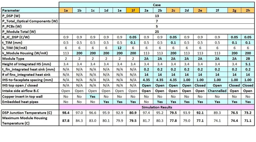
Table of Contents

Introduction                                                       2

Introduction to QSFP-DD and QSFP-DD800 modules                     3
   QSFP-DD and QSFP-DD800 Hardware Specification                  3
   QSFP-DD Module Cage Configurations                             5

Module Design Considerations                                      6

System Design Considerations                                      10
   General Design Considerations                                  10
   Faceplate Features                                             10
   Cage Heat Sinks                                                11
   Module-to-Heatsink Interface                                   11
   Internal Cage Features                                         12
   Belly-to-Belly Design                                          12
   Stacked Design                                                 13
   QSFP-DD800 Optimizations                                       14

Simulation and Experimental Thermal Analysis                      15
   Modules Under Test                                             15
   Simulation Setup                                               16
   Simulations Results                                            17
   2x1 Stacked Cages                                              18
   Vertically Configured 1x2 Cages                                19
   1x1 Cage Implemented in a Belly-to-Belly Configuration         20
   Alternate Cage Implemented in a Belly-to-Belly Configuration   20
   Simulation Analysis Key Takeaways                              21
   Experimental Thermal Analysis                                  21
   Experimental and Simulation System Testing Summary             23

System Thermal Testing                                            24

Summary                                                           26

Appendix I: Thermal Load Considerations                           28
                                                                  1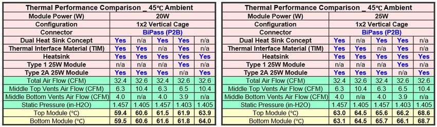
1 Introduction
While the goal for all optical modules is to dissipate as low a power as possible, it is necessary to design
systems to be able to handle the highest power module that a user may want to deploy in the system.
Because of that, there is always significant focus on the ability of a module form factor to be able to be
cooled in a system design up to the maximum power capacity that might exist within that form factor.
In this white paper, we will focus on the thermal performance of the QSFP-DD module that is
dominantly being used in high performance data center environments and the QSFP-DD800 module
that is soon becoming available. The optical modules, supporting coherent interfaces such as 400ZR or
OpenZR+, currently represent the highest power modules (15-20W) and the analysis and test data will
be shown to demonstrate the feasibility of cooling such modules. With the advent of QSFP-DD800 and
the likelihood of coherent optical modules requiring even higher powers, the whitepaper will explain the
techniques that are used in QSFP-DD module and system design and how those are not limited to just
the 20W targets of the QSFP-DD coherent optical modules.
A clear advantage of QSFP-DD and QSFP-DD800 module design is the flat-top aspects of the module
specification. This requires a riding heatsink to contact the module case instead of an integrated
heatsink. While this may not be the ideal approach to minimize the thermal impedance from the module
to the heatsink, the flexibility afforded by this approach allows significant optimization of all of the
critical components that positively impacts the overall performance. This yields results that far exceed
what was imagined when QSFP28 modules were designed for 3.5W and started pushing towards 5W.
The whitepaper will focus on 3 areas of interest for readers:
● The module design considerations to optimize for thermal performance
● The system design considerations to optimize for thermal performance
● Summary of testing with high-density systems
This whitepaper is organized in the following manner. An introduction to the QSFP-DD and QSFP-DD800
modules and specifications is followed by an exploration of some of the module design considerations
for high power thermal design. An overview of system design considerations then covers some of the
key considerations and techniques that can be utilized to build systems capable of supporting the
high-power optical modules. This is followed by a review of both experimental and simulation
experiments to demonstrate the principles discussed.
A lot of progress and learning has happened since the early days of the QSFP-DD module definition
when the QSFP-DD MSA published an earlier Thermal Whitepaper citing 15W in 2018. This whitepaper
will explore the improvements since then.
2
2 Introduction to QSFP-DD and QSFP-DD800 modules
The QSFP-DD module form factor is the industry’s smallest 400GbE module providing the highest port
bandwidth density. This form factor leverages the industry’s manufacturing capability and cost structure
that supports QSFP+ and QSFP28, the industry’s de facto sole standards for 40GbE and 100GbE.
QSFP-DD can support 36 ports of 400GbE in a single Rack Unit (RU) providing over 14 Tb/s of bandwidth.
The QSFP-DD module can support a variety of optical and copper cable interfaces:
● 3m of passive copper cables
● 100m over parallel multimode fiber
● 500m over parallel single mode fiber
● 2 km and 10km over duplex single mode fiber
WDM and Coherent designs
● Backward compatible hosts with all QSFP based transceivers from 40G to 200G
The QSFP-DD800 module form factor is the industry’s smallest 800G module capable of supporting
throughputs of 800 Gb/s. It is an extension to the QSFP-DD specification, with optimized signal integrity
performance supporting 8 lanes of 100 Gb/s electrical IO and maintains host backwards compatibility
with all other QSFP-based modules. The QSFP-DD800 module specification includes some
enhancements aimed at further improving the thermal performance as will be discussed below.
Due to the commonality of the thermal considerations between QSFP-DD and QSFP-DD800, this paper
will typically just refer to QSFP-DD but will call out specific differences for QSFP-DD800 where they exist.
2.1 QSFP-DD and QSFP-DD800 Hardware Specification
The Hardware specifications for QSFP-DD and QSFP-DD800 are available at www.qsfp-dd.com and
www.qsfp-dd800.com respectively. [Note: the QSFP-DD800 spec is in the process of being ported into
the QSFP-DD document, so it is recommended that readers view the QSFP-DD specifications for the
latest version]. The specifications cover the following items:
a) Electrical interfaces including pad assignments for data, control, status and power supplies and host
PCB layout requirements.
b) Optical interfaces (including optical receptacles and mating fiber plugs for multimode and
single-mode duplex and parallel fiber applications). Breakout cable applications are also specified.
c) Mechanical specifications including dimensions and tolerances for the connector, cage and module
system. Figure 2-1 shows the four variants of the QSFP-DD or QSFP-DD800 modules. They differ in the
details of the nose protrusion outside of the faceplate of the equipment, with Type 1 being consistent
with the QSFP28 mechanicals and Type 2 having a longer extension beyond the faceplate that module
manufacturers can take advantage of for extra design room internal to the module. Type 2A is a further
variant on Type 2 which has an integrated heatsink on the nose of the module to facilitate cooling with
an efficient secondary heat transfer path. Type 2B increases the height of the nose heatsink to take
advantage of the increased connector port separation defined for QSFP-DD800. All module variants are
compatible with the common QSFP-DD connector and cage designs and can be intermixed in a
deployment. Figures 2-2, 2-3 and 2-4 show generic 2x1 stacked, 2x1 stacked with high-speed cables or
1x1, respectively, connectors and cages with a cutaway view revealing the connector within the cage.
3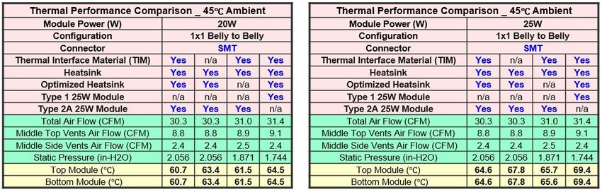
Figure 2-1: QSFP-DD module variants: QSFP-DD Type 1; QSFP-DD Type 2; QSFP-DD Type 2A; and QSFP-DD Type 2B

                              Figure 2-2: Stacked connector inside the 2x1 cage

                                                                                                            4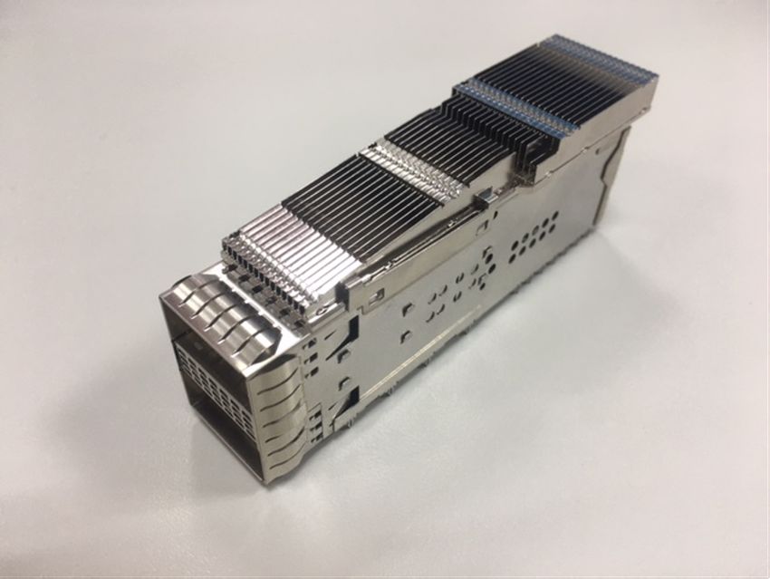
Figure 2-3: Stacked connector inside the 2x1 cage with high speed cables to top port

                              Figure 2-4: Surface mount connector in a 1x1 cage

2.2 QSFP-DD Module Cage Configurations
For maximum flexibility in system design the QSFP-DD cages are defined for both stacked and single
height configurations. (See Figure 2-5 and Figure 2-6). Figure 2-7 shows an image of QSFP-DD modules
plugged into a stacked card cage. Figure 2-8 shows two QSFP-DD800 type 2B modules seated in a
stacked cage. It is worth noting that the faceplate and cage airflow openings align with the nose
heatsink channels in order to maximize the effect of the heatsink.

    Figure 2-5: QSFP-DD stacked card cage                      Figure 2-6: QSFP-DD single card cage

                                                                                                      5
Figure 2-7: Copper cable and optical module in a QSFP-DD stacked card cage
Figure 2-8: Two type 2B modules shown in a QSFP-DD800 stacked cage. Note the alignment of the faceplate and
cage openings coincide with the nose heatsink channels
3 Module Design Considerations
The internal design of an optical module can have a large impact on the thermal performance of a
QSFP-DD module in a system. The goal of a system thermal design is to remove the heat from the
module case to ensure that the internal components within the module stay within certain temperature
ranges to ensure optimal performance and reliability.
In this section some of the considerations of the internal thermal design of the module and its impact on
the overall thermal performance is studied. The key parameters that influence the thermal performance
of a module are:
a) Total power dissipation. The power dissipation ranges of 400G client and line (ZR, ZR+) optical
modules are 10-14W and 16-20W, respectively. QSFP-DD800 modules are projected to dissipate 17-18W
(client optics) and 20-25W (line optics).
b) Power map (and module layout), i.e. location and power level of heat dissipating components,
c) Temperature limit of heat dissipating (and other, thermally sensitive) components. Optical
components / subassemblies (nITLA, TOSA, COSA) have the lowest case temperature limits (75-85C),
while the junction temperature limit of DSPs is 95-105C.
6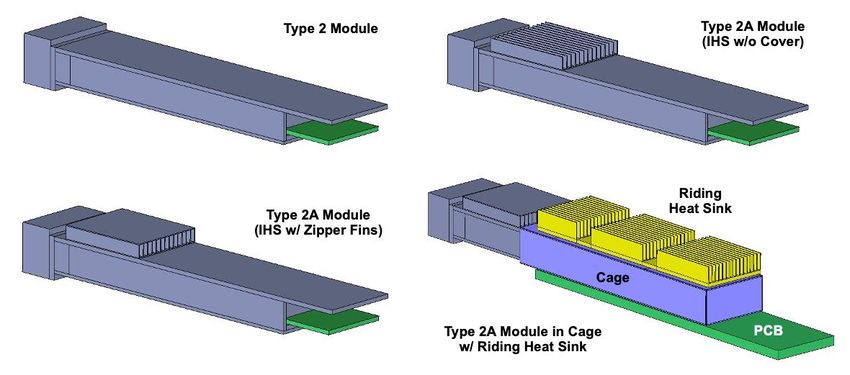
d) Thermal characteristics (e.g. junction-to-case, junction-to-board thermal resistance) and footprint of
high-power components (e.g. DSP, nITLA).
e) Efficiency of conduction paths (e.g. thickness and thermal conductivity of thermal interface materials,
wall thickness profile of module housing) from the heat dissipating components to module case to which
riding heat sinks are attached,
f) Material of module housing. The most frequently used material is ZAMAK 3, a zinc casting alloy with a
thermal conductivity of 113 W/mK. Materials with higher thermal conductivity, e.g. aluminum (k ~ 200
W/mK), in some cases, due to more efficient heat spreading, may offer thermal benefits.
g) Flatness of the top and bottom surfaces of the module housing to which riding heat sinks are (or
may be) attached. Improved surface flatness results in lower thermal contact resistance between the
module and its riding heat sink(s). The current flatness specification in the MSA for modules with power
dissipation of 10W and above is 0.050 mm. For high-power modules, 0.025 mm flatness would be
beneficial, but increased costs might limit the use of this option.
h) Type of module. Type 2A and 2B modules, with an integrated heat sink located on the front external
portion of the module, create an efficient, secondary heat transfer path from module to the cooling air
and offer thermal benefits for modules with certain power maps and proper internal thermal design.
A parametric study is carried out for a generic 25W module, in the worst-case data center ambient of
46C and with airflow boundary conditions typical of a 1RU system, to quantify the effects of the key
module thermal design parameters on component and module housing temperatures. Figures 3-1 and
3-2 show the boundary conditions (derived from system level) for the module-level analysis and the
thermal models of the module types simulated, respectively.
Fig 3-1: Boundary conditions for module-level analysis
7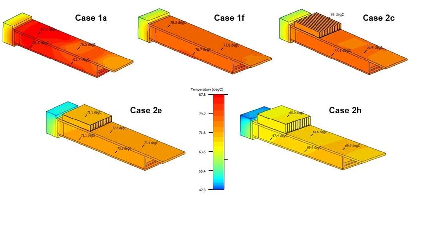
Figure 3-2: Thermal models of module types simulated
Depending on the location / vertical position of a given row of optics in a system, the linecard’s intake
side airflow boundary condition (B.C.) for a module can be Open or Channeled. In open airflow condition
the top row of optics receives unimpeded airflow from both the top and front, while in channeled
airflow condition an intermediate (lower) row of optics receives channeled airflow only from the front
through the channels formed between adjacent upper modules (see Figure 3-3).
Figure 3-3: Illustration of open and channeled airflow boundary conditions in a system
Table 3-1 contains the simulation matrix and results. The parameters that are changed compared to the
baseline case 1a are highlighted in blue. As the results reveal, with improved conduction paths (e.g.
using higher-conductivity module housing material, a copper insert or embedded heat pipes in the top
shell) the maximum surface temperature of the module housing can be significantly reduced even for
Type 2 modules. DSP junction temperature can be greatly lowered by reducing the thickness of thermal
interface material (TIM) between DSP and module housing, using high-conductivity TIM or DSP with
lower junction-to-case thermal resistance (R_JC). Type 2A modules – utilizing the additional conduction
paths and increased surface area offered by the integrated heat sink – further improve module cooling
efficiency. Integrated heat sinks (IHS) with closed top (cap) and within 1mm from the faceplate of line
cards or a system provide better cooling than open top IHSs in certain airflow schemes (e.g. short inlet
vent height). Figure 3-4 displays surface temperature maps of the module housing for select cases.
8
The results of the module-level analysis demonstrate there are many options to achieve thermally
efficient module designs and highlight the critical role of the supplier in building an overall thermally
managed / optimized solution.

                            Table 3-1: Modeling matrix and simulation results

                 Figure 3-4: Surface temperature map of module housing for select cases

                                                                                                            9
4 System Design Considerations
In the previous section, we explored the module design optimizations that can improve the thermal
performance of a module in a system and in this section we will explore the system design
considerations, options and optimizations that can improve the thermal performance of a system
cooling some high power pluggable QSFP-DD & QSFP-DD800 pluggable modules.
An effective thermal system design encompasses many considerations from overall linecard architecture
to specifics on heatsink and airflow management. We will explore some of the options for linecard
design as well as some of the considerations that are independent of linecard design. As front to back
airflow direction is the dominant system airflow direction utilized by the industry, this whitepaper
focuses its work on that configuration.
4.1 General Design Considerations
Thermal management of high-density systems involves:
● Selection and proper placement/configuration of high-performance air-movers / fans of the
right form factor that provide sufficient airflow rate to keep the temperature of all the
subassemblies and components of the system (optical modules and ASICs, retimers, POLs, CPUs,
which are located downstream of the optics) below their respective limits in both normal
operation and under fan failure conditions. In certain systems, such as in a 1RU enclosure, or
under certain low air flow conditions, air temperature rise just through the optics section can be
significant (8-10C),
● Optimization of board layouts, i.e., proper placement of components to meet signal integrity
and functional requirements while providing sufficient thermal estate for heat sinks. The best
arrangement of the optical modules (i.e., belly-to-belly or stacked design) is dictated by the
cooling requirements of the rest of the system.
● Heat sink optimizations to achieve the required cooling of each component while balancing
component thermal margins and minimizing pressure drops across the system, thereby,
minimizing the pumping power of the cooling system.
System designs for high density systems utilize different circuit board layouts, fan placement and air
flow control to allow optimization of routing, module placement and air flow.
4.1.1 Faceplate Features
Faceplate features play an important role on the thermal performance of optics and other downstream
components on the card. These features include but are not limited to:
● When Type 2A modules are used, faceplate should have openings/perforation aligned with the
nose heat sink of the top module
● While a flat faceplate allows more flexibility in terms of cage heat sink design by maximizing
faceplate height, use of slanted face plates allows more airflow into the system but requires
10tapering on the top heat sink of the cage. This is useful for dense port configurations (32 ports
and above in 1RU form factor) that allow limited airflow openings in between cages on the
faceplate.
4.1.2 Cage Heat Sinks
Riding heat sinks on the pluggable module cage are the main heat rejection path to the forced airflow
around them. Depending on the arrangement, heat sink placement varies. For example, for
belly-to-belly arrangements in 1RU, the cage is in 1xn (1 high by n wide) arrangement, the heat sinks are
only placed on the top of the cage. For stacked module arrangement, the cage is in 2xn arrangement,
heat sinks are placed both on the top of the cage and in the middle of the cage to provide contact with
the lower module. Both of the top and/or middle heat sinks can be optimized. The top heat sink shape,
size and design has more flexibility as it is outside the cage and only constrained by system and adjacent
component design. This flexibility is one of the inherent thermal advantages of the QSFP-DD family of
modules. The bottom module has less inherent flexibility of shape and size of its heatsink; however, it is
possible to have a heatsink to remove heat from the bottom surface which can balance out the
performance. Optimization of the heat sink designs for these two types of cage configurations has a
marked impact on the system’s thermal performance.
4.1.3 Module-to-Heatsink Interface
Heat sink pedestal is the part of the heatsink that physically connects to the pluggable module. Its size is
an important consideration. Maximizing the pedestal contact area of the heatsink to the module lowers
the thermal resistance and improves the system’s ability to cool the module. Of course, there are design
constraints that factor into maximizing the size of the pedestal. Small pedestal sizes may restrict
spreading therefore creating higher thermal resistance at the interface. As seen in the previous section,
improvements in the module’s top case thermal conductivity is important and is also related factor to
reducing the thermal resistance from the module to the heatsink
Regardless of the optical module arrangement (stacked vs. belly-to-belly), the interface between the
module(s) and the heat sink(s) on the cage Is important. Since this interface provides the main heat
conduction path between the hot components inside the module and the heat sink attached to the
cage, the contact resistance at this interface affects almost all of the component temperatures inside
the module. This interface resistance varies depending on how the contact is made, i.e., it could be a dry
contact (higher thermal resistance) or a thermal interface material (TIM) can be placed in between to
lower the thermal resistance.
In the case of a dry contact, the thermal resistance is lowered with increased surface co-linearity and
therefore surface flatness and roughness specification are included in the QSFP-DD and QSFP-DD800
MSA specifications for the module surface and system and cage designers can design the heatsinks
accordingly. The down force of the riding heatsink attach technique to the module is a factor here and
can also be a factor that reduces thermal resistance. While placing a coating or a thermal interface
material (TIM) can lead to lower thermal resistance, degradation of the metal-to-metal surface or the
TIM performance in time must be considered and should be balanced against the down force of the
design. Obviously, this can be a challenge for a pluggable module use case after a number of insertions
where the TIM may be worn and therefore result in increased contact resistance at the interface.
11Therefore, if used, TIM material selection is important. For example one could not use the TIM materials
used in high power ASIC assemblies in optic plug/cage assemblies as that TIM material is not typically
wear resistant. Degradation of the metal-on-metal surfaces or a TIM should be considered over
insertions. While there is no universal requirement, material with TIM performance that is expected not
to change after a couple hundred module insertions does exist.
4.1.4 Internal Cage Features
Inside the cage, openings and by-pass airflow channels around the connector affect both the hydraulic
and thermal resistance. Mechanical features can carefully be designed so that there is sufficient room
for by-pass airflow channels around the connector, which leads to a lower pressure drop for the cage,
and therefore produces higher airflow rate from which both the optics and downstream components
benefit. It should be noted that perforations on the cage walls should be placed in order to also maintain
the EMI requirements for the card/system.
4.2 Belly-to-Belly Design
A 'belly to belly' linecard layout places the modules and cages on opposite sides of a common circuit
board as shown in Figure 4-1. In this design the air flows on both sides of the printed circuit board
providing some advantages for cooling of the modules. It can be noted that it also gives a less complex
signal integrity design of the high-speed traces into the modules as compared to a stacked card cage.
The advantage of this line card design is that it creates an independent and uniform cooling
environment between the upper and lower rows of modules on the faceplate. As noted earlier, the cage
heatsinks can be optimized to the broader system design providing flexibility. This line card design
approach is common in the 1RU height fixed systems where the limited fan heights can yield less airflow,
so separation of the thermal environments of the pluggable modules has benefit. The obvious challenge
of this design is the limited height of components on the rest of the printed circuit board and the
consequent reduced height of the heat sink on the limited number (typically only one) high power
switch chips that are downstream of the optics. It is outside the scope of this whitepaper, but advanced
heatsink designs are well known to enable cooling of these switch chips which can spread their surface
area in order to capture the upper and lower airflows in the system. From the optics cooling standpoint,
the challenge is on the limited size of faceplate vents and fin height of the top heat sink. As discussed
earlier, faceplate and heatsink design optimizations can address these challenges.
12Figure 4-1: Belly-to-belly QSFP-DD card cages
4.3 Stacked Design
A ‘stacked’ linecard layout places the modules and cages on the same side of a common circuit board as
shown in Figure 4.2. In order to stack the modules into two rows along the faceplate, a stacked
connector and cage is used, typically in a 2xn configuration. In this design the air flows primarily on one
side of the printed circuit board. This provides advantages for cooling of the downstream components
on the PCB, and especially the switch chip because this particular design allows maximizing the heat sink
height.
The key thermal challenge of the stacked cage linecard design is cooling of the bottom side module in
the stacked cage. Before focusing on the specific challenges, it is worth noting that there are some
broader inherent thermal advantages of the stacked cage designs. For all other components on the PCB,
there is increased maximum component height allowing for better heat sinking. Typically the stacked
cage designs are found in modular linecard systems where much larger and stronger fans are used
providing an increased airflow compared to a fixed 1RU design. This does not imply that a stacked
design in a 1RU is not feasible, just that it is perhaps the most challenging configuration from an optical
module thermal perspective.
In the stacked designs, heat sinking options for the bottom module are more limited compared to those
of the top module in stacked designs. There are a number of things to consider.
The use of an internal riding heat sink (IRHS) which is a heatsink that resides inside the cage between the
upper and lower modules and contacts the lower module within the airflow that passes through that
channel. The IRHS is the foundational innovation for QSFP-DD that enables thermal performances to
meet requirements. Width and height of the IRHS are more restricted than those of the top heat sink as
they reside within the cage. This leads to a heatsink with constrained fin height and surface area
requiring careful optimization to maximize thermal performance. Some factors to consider with this
optimization include:
● Heatsink optimization to ensure airflow impedance is minimized to increase the airflow rate
through the IRHS
13● A tradeoff exists between maximizing fin surface area for cooling and maximizing heatsink base
thickness for increased heat spreading.
Figure 4-2: Stacked QSFP-DD cages
Overall, while it has some disadvantages, stacked design has many system design advantages compared
to those of belly-to-belly design and both variants can be used to effectively cool pluggable modules.
4.4 QSFP-DD800 Optimizations
With the learnings from QSFP-DD system developments, some optimizations for QSFP-DD800 have been
incorporated into the MSA specifications.
The cooling of the bottom module within the stacked cage designs can be improved with increased
spacing between the upper and lower port to increase IRHS heatsink surface area and lower airflow
impedance through that channel. This increased spacing also enables a higher nose heatsink height
which is defined as a Type 2B module variant in the QSFP-DD800 specification. These changes result in a
12% improvement as shown in the earlier section.
Also for the QSFP-DD800 specification, the bottom surface of the module is defined as a potential heat
removal path for the system. By defining a flatness and roughness spec for that area of the module,
system designers have the option to include a heat sink that can be placed at the bottom and attached
to the bottom module via a thicker pedestal through the cutout on the PCB. Figure 4-3 depicts a bottom
heat sink attached to a stacked cage.
Figure 4-3: Bottom heat sink attached to a stacked cage
145 Simulation and Experimental Thermal Analysis
In order to assess the relative merits of different system design options a series of simulation and
experimental tests are executed using different configurations of cages, modules or system design.
5.1 Modules Under Test
The testing is performed using thermal test modules available from MultiLane. The modules have
multiple thermal loads throughout the internal cavity of the module to allow simulation of different
placements and powers of internal components.
Figure 5-1. Details of the thermal module used; when a Type 2A module is used, the nose heatsink is
implemented as depicted
The testing is carried out with thermal profiles that are representative of modules that dissipate either
20W or 25W. Some details of the thermal module are shown in Figure 5-1 with an example of the
15power profiles within the module shown in Figure 5.2 for the 25 W module. The modules have five load
zones, 3 above the internal PCB and 2 below the PCB which is consistent with typical module design.
For a 25W module the specific loads used are (top: nose to rear, bottom: nose to rear) 6W, 3W, 12.1W,
1.6W and 2.3W. For the equivalent 20W module the specific loads are 4.8W, 2.4W, 9.7W, 1.3W and
1.8W.
Figure 5-2: Power load distribution used for this analysis for a 25W module
5.2 Simulation Setup
As noted earlier, there is significant flexibility on how the cages for the QSFP-DD and QSFP-DD800
modules can be implemented on the linecard. For this comparative analysis, four different
configurations are used:
1. Stacked 2x1 cage. Upper and lower modules housed within the same cage and signals
connected to PCB through surface mounted connector. See Figure 5-3.
2. Stacked 2x1 cage. Upper and lower modules housed within the same cage and signals
connected to PCB through surface mounted connector for the lower port and high-speed cable
to the upper port. See Figure 5-4 .
3. Vertically configured 1x2 cage where modules are oriented 90° from a typical line card
implementation. See Figure 5.5.
4. 1x1 Cage implemented in a belly-to-belly configuration on either side of the PCB. Connectors
are surface mounted to the PCB. See figure 5-6.
All the simulation analysis occurs in a 1 RU high form factor with 6 modules under test with 3 upper and
3 lower modules. In all cases the results are taken from the middle module in each upper or lower row.
The ambient air temperature is 45°C and the maximum air flow-rate is 37.9 CFM. The spacing between
the cages is 3mm for the 2x1 stacked and belly-to-belly configurations and 1mm for the vertical stacked
configuration.
An attempt is made to have consistent boundary conditions between the configurations but it should be
noted that in reality each configuration would have its own design optimizations. Therefore, while the
simulations show that it is possible to design effective thermal solutions using any of these
configurations, the simulation results are more focused on understanding some of the improvements
from design variants within a configuration than showing a definitive comparison between the different
16configurations. When an internal riding heatsink is used (in stacked cage simulations), this was
consistent across simulations.
Figure 5-3: Stacked 2x1 cage Figure 5-4: Stacked 2x1 cage with cabled upper
port
Figure 5-6: 1x1 cage implemented in a belly-to-belly
Figure 5-5: Vertically configured 1x2 cage
configuration
5.3 Simulations Results
For each configuration, simulations are performed with a number of variants to enable comparison of
different aspects. In each case, the module case temperatures are reported for the middle, upper and
lower modules with the goal of maintaining a 70°C case temperature at the module nose location. In all
cases, a copper zipper heatsink is used.
Tested variations include:
● 20W and 25W thermal module model consistent with Type 1 or Type 2A mechanicals
17● Impact of a dual Heat Sink where an additional heatsink is used under the bottom module to
remove heat from the bottom surface of the lower module (for 2x1 cages)
● Use of a thermal interface material on the heatsinks to improve thermal conductivity
5.3.1 2x1 Stacked Cages
The simulation results for the 2x1 stacked cages and 2x1 stacked cages with high-speed cable to the
upper port are shown in Tables 5-1 & 5-2 respectively.
Table 5-1: Results from 2x1 stacked cage simulations
Table 5-2: Results from 2x1 stacked cage with high-speed cables to upper port simulations
There are some key observations for these experiments and as can be seen there is considerable
consistency between the two configurations indicating that the cabled upper port has little to no impact
on the airflow and cooling.
18In both configurations, both the 20W and 25W modules are cooled below 70°C case temperature. The
results of different experimental variations provide some insight into different impacts each technique
offers.
It is clear that the Type 2A module configuration, where there is a heatsink on the module nose provides
a marked improvement. In both sets of experiments, the Type 2A heatsink offers ~5 to 7°C reduction for
a 20W module and ~6.5 to 9°C for a 25W module. This is consistent with our earlier module-specific
simulations where we see that improved thermal conductivity across the module top surface and
heatsink area is effective. In addition to that, it can be seen that the bottom port benefits more than the
top port from the Type 2A module. This is mainly because of the channeled airflow condition that the
heatsink on the bottom port module nose experiences versus the open airflow condition that the
heatsink on the top port module nose experiences.
Consistent with this finding is that improved thermal conductivity between the heatsink and the module
through the use of a thermal interface material or coating has similar improvements of ~2.0°C for a 20W
module and ~2.5°C for a 25W module.
When a dual heat sink strategy is deployed with a small heatsink below the lower module (assuming a
flat-bottom spec as outlined for QSFP-DD800), it is found that this provides improvements for the lower
module of up to 2.8°C for a 20W module. The improvement for the two different power levels is found
to be similar. Due to the redistribution of airflow, the addition of the dual heatsink makes the top port
hotter by ~1.7°C. This is not a concern since there is enough margin available for the top port relative to
the bottom port. It is also important to note that the advantage of a dual heatsink strategy may not be
as evident when considering the module nose temperature; however, the advantages are more
prominent when looking at the temperature of internal components located inside the module such as
the DSP junction temperature.
Finally, the impact of an increased spacing between the upper and lower modules is measured in the
case of a stacked cage with high speed cables for the upper port. As discussed above the QSFP-DD800
specification is modified to increase this dimension to improve the airflow to the lower module. This
improves the cooling of the lower module and as can be seen with these results it can provide a 2.3°C
reduction in case temperature for the lower port. This reduction is seen when the effect of increase in
the spacing is simulated in the presence of a dual heatsink for the bottom port. Based on similar studies
done, the reduction without the dual heatsink is seen upto 4.3°C. It is noteworthy that these
experiments use the Type 2A heatsink dimensions which take advantage of the improved airflow but
results would have shown further improvement if the Type 2B heatsink with its higher fin height was
used to take better advantage of the increased spacing.
5.3.2 Vertically Configured 1x2 Cages
Despite the 90° rotation in the orientation of the modules relative to the typical configuration, the
simulation results provide a similar story as the 2x1 stacked cage results. The Type 2A module type
offers advantages over a Type 1, with improvements of 2.5°C and 3.2°C for the 20W and 25W modules
respectively. These improvements are not as much as the improvements seen in the stacked
configurations. This is because for this particular comparison the vertical approach allows significantly
larger inlet perforations which while bringing the advantage of overall greater airflow through the riding
19heatsinks results in air bypass from the module heatsink (which results in lower air velocity through the
module heatsink). Design optimizations can be done to take full advantage of the type 2A module.
Adding heatsinks through the bottom surface shows improvements of 1.2°C and 1.5°C for the 20W and
25W modules respectively and improving thermal conductivity to the heatsink by incorporating a
thermal interface material shows improvements of 2.1°C and 2.6°C for the 20W and 25W modules
respectively. The addition of the dual heatsink does not show as much improvement at the module
nose location since for this comparison when the bottom dual heatsink is removed to quantify its
benefit the top heatsink is grown by the same amount to maintain the same pitch. These results are
shown in Table 5-3.
Table 5-3: Results from 1x2 vertical cage configurations simulations
5.3.3 1x1 Cage Implemented in a Belly-to-Belly Configuration
The 1x1 cage implemented in a belly-to-belly configuration is perhaps the most thermally relaxed
configuration for the optical modules. By partitioning the upper and lower ports on a faceplate from
each other into their independent cooling environments, it allows the system designer to balance the
designs. As you can see from the results in Table 5-4, the upper and lower ports show consistent values
and all the previous findings still hold true.
Table 5-4: Results from 1x1 cage belly-to-belly configuration simulations
205.3.4 Alternate Cage Implemented in a Belly-to-Belly Configuration
As previously discussed, one of the benefits of the QSFP-DD family of modules is the flexibility in design
that allows alternate implementations that may offer optimizations. An example of this is shown in
Figure 5-7 where an alternate heatsink and cage design is possible that uses a heatsink attach
mechanism built directly into the cage and does not require additional clips to secure the heatsink to the
cage body. This alternate form is documented in the QSFP-DD Specification Annex. The results shown in
Table 5-5 demonstrate the thermal performance of the alternate cage solution in a belly-to-belly
configuration. The simulation boundary conditions are as close as possible to the previous simulations
documented in this section, however, differences in the model geometries will have an impact on the
results. As such, the results will vary slightly from the other belly-to-belly simulation results documented
in this section.
Figure 5-7: 1x1 alternate cage implemented in a Table 5-5: Results from 1x1 alternate cage
belly-to-belly configuration belly-to-belly configuration simulation
5.3.5 Simulation Analysis Key Takeaways
The previous section has covered module, cage and connector variations. This provides the system
designer many options when designing their full system configuration. From a thermal perspective,
there are a few key takeaways that emerge from all of this analysis. As we know from the previous
section, improved heat removal from the top surface of the module is the primary optimization the
system can make to support the module cooling. As such, the key takeaways regardless of configuration
are:
● For higher power modules, the nose heatsink (either Type 2A or Type 2B) has significant impact
● Increased airflow through reduced impedance around the module improves results either by
changing the configuration (1x1 vs 2x1 vs vertical cages) or optimizing the spacing between
modules in a 2x1 cage configuration
● The dual heatsink approach does provide incremental improvement but is secondary (and
additive) to the main points above
215.4 Experimental Thermal Analysis
To compare the differences between different cage configurations, a 1 RU system is designed with the
four different cage configurations implemented across the faceplate. By measuring the temperature
rise of the modules under common conditions it is possible to investigate any trade-offs between the
different configurations. Said configurations are grouped across the faceplate as shown in Figure 5-8.
Figure 5-8: Experimental configurations showing the top view and front view of the four cage
configurations under test
A series of tests are run using MultiLane thermal modules of a QSFP-DD Type 1 module. We know from
the previous sections that this is not the optimal module variant for higher power modules where a Type
2a or Type 2b should be used but for a comparative study, it yields informative trends. A mix of modules
operating at 20W and 15W are used, the majority of which are rated to 15W due to module availability
at the time of testing. The system has a common fan tray that provides even airflow across the width of
the unit.
By adjusting the fan speed, 3 different sets of measurements are made. In each case the airflow for the
specific cage configuration is measured to assess relative airflow impedance of the different
configurations and the increase in module case temperature above ambient is measured.
The results from the 3 different fan-speed tests are shown in Figures 5-8, 5-9 and 5-10. In each figure,
the module powers are shown and the module temperature rise is indicated by the red display on the
thermal modules.
22Figure 5-8: Test results with 85% fan-speed
Figure 5-9: Test results with 93% fan-speed
Figure 5-10: Test results with 100% fan-speed
23In all cases, independent of cage configurations or fan-speed, the temperature rise is well below the
target of 30°C, which is typically the target in a system design being used in a data center environment.
The configurations differ slightly between each other but not in highly significant ways. The major
observable difference is the airflow impedance being lower for the vertically configured 1x2 cages; this is
owing to the increased faceplate air openings. The high airflow (resulting from the low impedance)
coupled with dual heatsink allows the 1x2 Vertical configuration to cool an extra 5W while maintaining
similar margins.
The maximum ΔT at 15 W is 19 °C as can be seen from Figure 5-10. Linear extrapolation to 25 W results
in a maximum ΔT of ~32 °C. Assuming a ΔT of 30°C is the requirement in most systems, these results
are encouraging as, even with the Type 1 module used here, it comes close to meeting this target and
we know from above that the Type 2A or Type 2B variants would actually be used and would provide
considerable improvement.
5.5 Experimental and Simulation System Testing Summary
In Section 5, a range of configurations and variations of system design using QSFP-DD modules are
explored. The goal is not to identify the best approach but rather to demonstrate that a very broad
breadth of options exists to allow system architects to optimize the overall design incorporating the
optics, ASIC, power and control subsystems together.
In all of the above variations, it is shown that a viable path to cooling high-power QSFP-DD modules is
available.
6 System Thermal Testing
A 1RU TOR (top of rack) switch equipped with 6 of 40mm X 56mm dual rotor fans are presented as an
example for system design. 32 of QSFP-DD ports are supported in this 1RU TOR. Average air flow rate for
each QSFP-DD port is about 3.75CFM at max fan speed. The PCB is placed at the center of the chassis
horizontally. It allows all QSFP-DD ports to receive evenly distributed air flow for optimized cooling
performance. Figure 6-1 shows the distribution of QSFP-DD ports at the front panel.
Figure 6-1: Front panel of 1 RU top of rack with 32 ports of QSFP-DD
Figure 6-2 shows temperature distribution of FR4/DR4 in the 1RU system. The temperature reading is
reported from the internal sensor of optical modules.
24Figure 6-2: Temperature distribution of optical modules (400GBASE-DR4 and 400GBASE-FR4)
MultiLane ML4062-TL2a Modules are used to evaluate cooling capability of 800G (QSFP-DD800) (Figure
6-3(a)). ML4062-TL2a is programmable to emulate the thermal behavior of an optical module. Figure
6-3(d) shows the location of the power spot. For example, this experiment configures the module to
consume 20W by adjusting the resistors (Figure 6-3(b)). There are 4 thermal sensors pre-built within the
ML4062-TL2a for real-time temperature monitoring (Figure 6-3(c)). Sensor 4 is used as a critical
temperature and has +/- 3°C compared to temperature read externally at the Tc area (hot spot) (see
Figure 6-3(a)).
Figure 6-3 (a) MultiLane ML4062-TL2a DD module; (b) power setting for 20W; (c) location of thermal
sensors inside the ML4062-TL2a; (d) location of power spot inside ML4062-TL2a
25Figure 6-4 shows the temperature of MultiLane ML4062-TL2a (20W) in a 1RU chassis. The air flow is
port-intake. The average temperature across all modules is 45.8°C in a 25°C ambient chamber
environment, i.e., 20.8°C temperature rise. By mathematically adjusting the data to emulate a 40°C
environment and 1800 m altitude, in this case the average temperature across all modules will be
66.8°C, i.e., 26.8°C temperature rise.
Figure 6-4: Temperature distribution of optics module (MultiLane ML4062-TL2a DD Module) in 1RU
chassis, chamber temperature is 25°C
Figure 6-5 depicts the average temperature of ML4062-TL2a DD Module with various power settings as
a function of fan speed.
26Figure 6-5: Average temperature optics module (MultiLane ML4062-TL2a DD Module) in 1RU chassis vs
fan speed, chamber temperature is 25°C
Considerations:
At max fan speed the ΔT between Tambient and Tc is below 25°C also in case of module power
consumption at 23.4W. With 20W power consumption, we have a ΔT around 25°C with fan speed at
80%.
7 Summary
QSFP-DD represents a module form factor that offers a low cost solution that leverages years of past
system and module/cage thermal experience. With its flat-top design, it offers the greatest flexibility to
the thermal architect to customize their products in order to balance all of the requirements between
the optics, the ASIC, the power and the control subsystems.
The reality is that the goal and the trend for optical modules is to reduce the power as much as possible.
With many of the reaches of interest, which represents the majority of the deployments, power levels
are very manageable and the system can easily support these thermally. However, as a system designer,
it is imperative that the system can support the highest power modules (typically coherent optical
modules) in order to provide the end user the flexibility they desire to be able to insert any module into
any port.
This white-paper explores the system and module design challenges at these high-power limits of the
optical modules and shows that many options exist to successfully cool these modules.
It is shown that the internal design of the module has a strong impact on performance that can be
leveraged by module designers with a variety of techniques.
27Similarly for the system designer, it is shown that there are a lot of strategies around the cage and
heatsink design as well as the modules configurations across the faceplate that have marked impact on
the overall thermal performance.
The advent of the module nose heatsink (known as Type 2A, or Type 2B) is shown to be highly effective
in giving these very high-power modules the extra thermal performance they need. For the 400G
designs of QSFP-DD with powers around 20W and for the 800G designs of QSFP-DD800 with powers
anticipated up to 25W, it is found that existent solutions provide a plethora of design trade-offs for the
system.
In conclusion, QSFP-DD family of modules continues to deliver a viable, versatile, and broadly supported
set of solutions for every use-case that a system designer or end-user would need to consider.
28Appendix I: Thermal Load Considerations
The development of systems and pluggables to accommodate next-generation port speeds often occur
in parallel. As the objective of this publication is to recommend design optimizations for interconnect
technologies that may be in early development stages, there is a need to emulate the thermal profile of
pluggable modules in a cost-effective and scalable manner.
QSFP-DD loopbacks that simultaneously act as thermal loads support this requirement. A single module
produces the thermal signature of a variety of transceiver designs, depending on which internal hotspots
are enabled via programmable power dissipation (see Fig. A1). In addition to supporting high speed
traces to “loop back” TX signals to the RX side, the modules include CMIS firmware to validate
host-module interop, enabling the industry to accelerate their designs to market against a well-defined
set of guidelines.
Figure A1: Thermal load hotspots
29You can also read