Orientation Aid for the Start of the Season
UF02 with ISOBUS
←
→
Page content transcription
If your browser does not render page correctly, please read the page content below

Orientation Aid for the Start of the Season UF02 with ISOBUS

Service Training

Table of Contents

1. General information
2. Start screen of the implement software
3. Work menu of the implement software
4. Preparation for operation
5. Procedure during operation
6. Software settings
7. Preparations on the implement - Task Controller

2021 / Status 01                                               Page 2

Service Training

1. General instructions
•    Use of this document requires that the operating manuals for
     the implement and the software have been read and
     understood. The corresponding documents are shown on the
     left side.
•    For this reason, it is necessary to take additional information
     from the operating manual. The operating manual must
     always be available when performing the orientation aid for the
     start of the season with the UF02.
•    The Orientation Aid for the Start of the Season - UF02
     ISOBUS document serves as a guideline for the user to check
     the implement for the new season and to put it back into
     operation. The figures and screenshots in this document refer to
     model year 2021 and software version NW242-F, and are only
     valid for this. There can be differences in the figures and
     screenshots for an implement from a different model year
     and/or a different software version.

2021 / Status 01                                                                  Page 3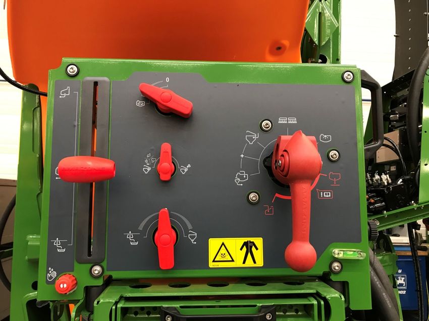
Service Training

2. Start screen of the implement software
•    The Main menu is divided into the Field menu (1) and the
     Settings menu (2).
•    The menus can be switched by clicking on one of the              1
     marked buttons.
•    From the Field menu, you can switch to the submenus
     Work, Documentation, Filling, Cleaning and Agitation.
     Moreover, it is also possible to enter the desired application
     rate in l/ha here.
•    From the Setting menu, you can switch to the submenus
     Implement, Profile and Info.

                                                                                       2

2021 / Status 01                                                                    Page 4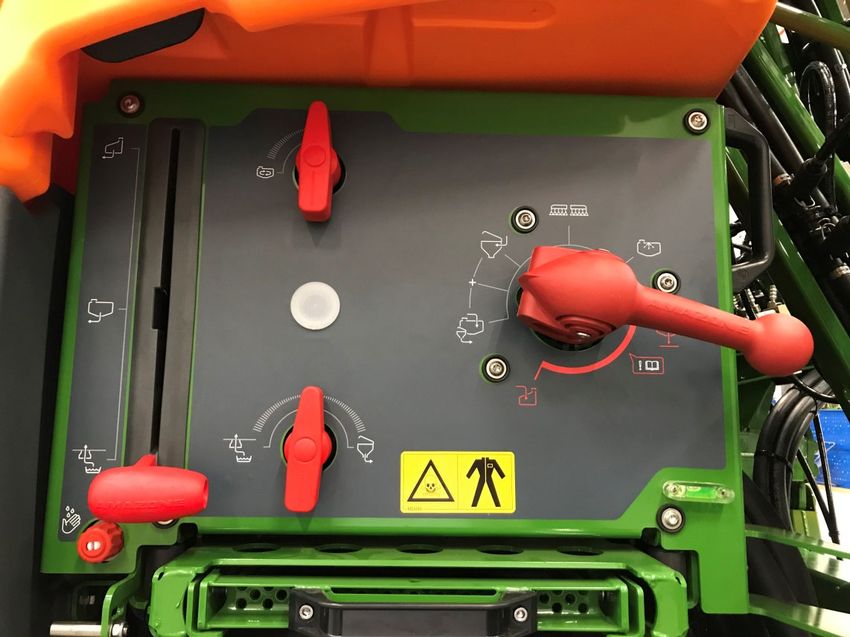
Service Training

3. Work menu of the implement software
                                                                               13                  14                               25             27           32

                                     1                                                                              20              26             28           33

                           3                        4                           15                16                                                            34
                                                                                                                    21              25             29
                                                    5
           2
                                 7                  6                                                                                                   35           36
                                                                                          17                        22                        30

       8
                                                                                          18              23                  24              31        37           38
                             9                      10

                                                                                                                                                        39           40

                        11               12

(1)    Multi-function display, freely configurable, see operating manual for   (21)   Tilt boom up on one side on the left / right *
       more information                                                        (22)   Tilt boom down on one side on the left / right *
(2)    Display of the total fill level                                         (23)   Switch DistanceControl automatic boom guidance on / off *
(3)    FlowControl+ status *                                                   (24)   Save spraying height
(4)    Application rate                                                        (25)   Increase/reduce application rate
(5)    Percent value of the application rate                                   (26)   Reset application rate percent value to 100%
(6)    Spray pressure                                                          (27)   Switch spraying on / off
(7)    Section Control status                                                  (28)   Switch automatic rate control on / off
(8)    Part-width section status                                               (29)   Switch on Section Control
(9)    Boom status display                                                     (30)   Switch part-width sections off
(10)   Edge nozzle status *                                                    (31)   Switch on the part-width sections
(11)   Boom illumination status *                                              (32)   Switch end nozzles off / on *
(12)   Flushing water pump status *                                            (33)   Switch boundary nozzles off / on *
(13)   Mirror tilt adjustment                                                  (34)   Switch extra nozzles off / on *
(14)   Lock/unlock boom                                                        (35)   Switch flushing water pump on / off *
(15)   Fold/unfold boom on both sides                                          (36)   Start the start functions
(16)   Boom lifting / lowering                                                 (37)   Switch automatic FlowControl+ on / off *
(17)   Tilt boom to right / left                                               (38)   Stop FlowControl+ pumping *
(18)   Angle boom up/down on both sides                                        (39)   FlowControl+ pump to the front *
(19)   Fold boom on one side on the left / right *                             (40)   FlowControl+ pump to the rear *
(20)   Unfold boom on one side on the left / right *                                                                                                         *Softkeys depend on the equipment
2021 / Status 01                                                                                                                                                                         Page 5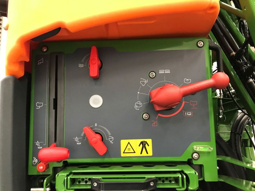
Service Training

4. Preparation for operation
Tractor requirements - UF02                                                                                                             1

Version                            Tractor engine power

UF1002                             Above 55 kW (75 HP)

UF13002                            Above 66 kW (90 HP)

UF1602                             Above 90 kW (125 HP)

UF2002                             Above 100 kW (137 HP)

•    Tractor pump capacity: at least 25 l/min at 150 bar, max 210 bar (with Profi-folding).                                             2

•    Connections, depending on the implement equipment, the following connections are required:
                   1x pressure-free return flow T (max. 5 bar)
                   1x pressure line P (max. 210 bar)
                   1x load sensing control line
                   Or:
                   3x DA height adjustment, boom folding and tilt adjustment
                   Or:
                   2x DA height adjustment, tilt adjustment

Coupling the implement: if the tractor is being coupled to the mounted sprayer for the first time, be sure to observe section 8 of
the implement operating manual.
To couple the sprayer with the quick-coupling system, the lever must be set to the raised position when approaching (1). If             3
necessary, adjust the length of the top link so that the quick-coupling system can be locked.
Pick up the implement with the lower links and couple the top link, secure the implement. Fold in the parking rollers/parking
support. Take the ISOBUS, lighting, hydraulic system, universal joint shaft, hose lines (front tank) from the parking positions (2)
and couple them. Align the implement horizontally (3). Pay attention to the ballasting and dimensions of the implement
combination (UF+FT). Depending on the road traffic regulations, use front cameras or a banksman for road travel.

2021 / Status 01                                                                                                                                Page 6
Service Training

5. Procedure during operation
Filling
Spray liquid tank suction filling:
(1) Run the pump.
(2) Move the suction tap to "Suction via suction
    hose".
(3) Set the pressure tap to "Fill spray liquid tank".
(4) Set the injector switch tap to "Increase filling                3
    capacity via injector".
                                                                4
                                                        2

Pressure filling of the spray liquid tank
(optional):

(5) Set the pressure filling switch tap to "Fill
    spray liquid tank".
The position of the other taps on the control               5

panel are not relevant for pressure filling.

2021 / Status 01                                                                  Page 7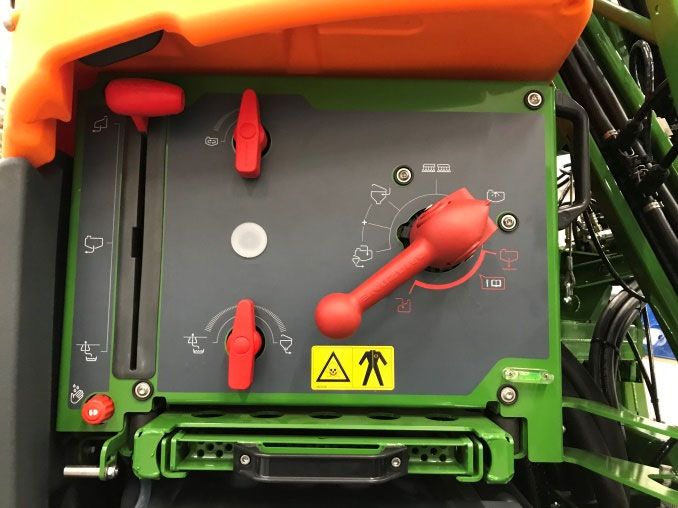
Service Training

5. Procedure during operation
Induction bowl
The induction bowl can be supplied via:
         • the suction connection                                                 1
         • the pressure connection (optional)
                                                                                              2   3
 (1).                                                                                                 4   5
The following functions can be switched on at the induction bowl:
1. Spray pistol for cleaning the induction bowl (2)
2. Mixing nozzle for flushing in powders or pellets (3)
3. Canister cleaning (4)
4. Ring line to dissolve and flush in crop protection agents (5)
Supply via the suction connection:
1. Start a suction filling of the spray liquid tank. (6)
2. Set the pressure tap to the "+" position (7)
3. If necessary, activate the taps on the induction bowl. (2-5)
4. To suction the induction bowl empty, set the injector switch tap to
     "Suction from induction bowl". (8)
                                                                                              9
5. To increase the pressure on the induction bowl, e.g. for canister
     cleaning, set the pressure tap to "Supply induction bowl". Caution!                  7
     The induction bowl is not suctioned empty in the process (9)
Supply via the pressure connection:
1. Start the pressure filling
2. Pressure filling supply (1)
                                                                                      8
3. Pressure tap in the "+" position (7)                                       6
4. Run the pump
5. Suction the induction bowl empty (8)
6. For more pressure, e.g. for canister cleaning, stop the pressure filling

2021 / Status 01                                                                                                Page 8
Service Training

5. Procedure during operation
After the sprayer has been filled and
the crop protection products have
been flushing in, the pressure tap
must be switched to "Spraying". (1)          2

Agitation
                                                 1
Agitating intensity:
The valve chest is used to infinitely
variably adjust the agitating intensity on
the control panel. (2)

2021 / Status 01                                               Page 9
Service Training

                                                                                                                        4

5. Procedure during operation                                                                                           1

                                                                                                                    5
Move boom to working position                                                                              3

(1)Lift the boom.                                                                                                       2
(2)With Profi-folding 2, angle the boom completely up on both sides.
                                                                                                           7             6
(3)Unfold the boom to the desired working width.
(4)When the boom is completely unfolded, the boom can be unlocked.
(5)Move the boom to the desired spraying height.
(6)Save the spraying height. *
(7)Switch on the automatic boom guidance. The boom must be completely unfolded and
                                                                                                               8
   unlocked! *
* Only with the optional DistanceControl boom guidance.

 Spraying                                                                                              9
1. Per default, the automatic rate control is activated (11). On the right of the spray liquid tank,
     information on the application is shown (see page 5) (8).
2. Switch on the main part-width section switch (10).
3. Switch on Section Control (12). To be able to activate this function, the following conditions
     must be met:
     • Section Control of the terminal (Task Controller) activated
     • Implement error free                                                                                                 10
     • Booms in working position
Depending on the setting, the softkey (12) may not be visible in the Implement menu, but may
                                                                                                                         11
rather appear in the GPS view. You can find more information about the Section Control settings
in the operating manual for the implement software and the terminal.
4. You can see the status of Section Control based on the symbol (9):                                                       12
     • Grey X: Section Control is not active on the implement and on the terminal
     • Symbol flashing in colour: Section Control is active on the terminal, but not on the
          implement
     • Symbol not flashing in colour: Section Control is active on the implement and on the
          terminal

2021 / Status 01                                                                                                                 Page 10
Service Training
5. Procedure during operation
Manual cleaning 2
3
1
If the implement is equipped with a manually operated valve chest,
follow these steps to perform a quick cleaning.
1. Run the pump.
2. Make sure that the pressure tap is set to the "Spraying" position
(1).
3. Move the suction tap to the "Suction from the flushing water
tank" position (2).
4. Open the agitator (3).
5. After 10 % of the flushing water supply has been used up, close
the agitator (4).
6. Move the pressure tap to the "Cleaning" position (5). 4
7. After another 10 % of the flushing water supply has been used
up, close the cleaning (5). 5
8. Move the suction tap to the "Suction from the spray liquid tank" 6
position (6).
9. Set the pressure tap to the "Spraying" position (1).
10. Spray out the cleaning water until air emerges from the nozzles.
Switch the part-width sections (7) on and off several times in the
process. Also switch the edge nozzles (8) if necessary.
For intensive cleaning, repeat the steps 1 to 10 for a total of three
times.
11. Drain the final residual quantity (9). 10
12. Clean the suction filter and pressure filter (10). 9
8
7
2021 / Status 01 Page 11Service Training
6. Software settings
• (1) Configuring the part-width sections: 1
Settings menu > Profile > Part-width
section control. Here, each part-width
section can be configured.
• (2) Headland pressure: Setting menu >
Profile > Rate control. Here, the desired
headland pressure can be set.
• (3) Start-up ramp: Settings menu >
Profile > Rate control. Here, the "start-up
ramp" can be configured. After switching
on the sprayer, an increased quantity will 2 3
be metered for the entered start-up time /
until the entered start-up speed is
reached.
• (4) Configuring the working height and
headland height: Setting menu > Profile
> Boom behaviour. The working height
can be set in cm and the headland height
in steps: off, low, medium, heigh, and
maximum.
4
2021 / Status 01 Page 12Service Training
7. Preparations on the implement - Task Controller
• Terminal: the functions of the Task 1 2
Controller are controlled via the terminal.
The terminal must be prepared accordingly.
You can find more information in the
operating manual for the respective
terminal.
• (1,2) Switch-on and -off time: Settings
menu > Profile > ISOBUS. These times
define the delay between the moment
when the terminal issues the command to
switch the part-width sections on or off and
3
when the implement really executed this
command. Incorrect settings can cause
overlaps or gaps.
• (3) Task Controller: Setting menu > Profile
> ISOBUS. Under the Documentation
point, there is the choice between
"Implement internal" and "Task Controller".
• (4,5) Application maps / jobs: the "TC"
icon on the Work menu and Field menu
indicates that the implement is receiving
the target application rates from the Task 4 5
Controller (application map or job).
2021 / Status 01 Page 13SmartLearning app Info Portal
The AMAZONE SmartLearning app offers Our Info Portal provides a wide variety of
video training courses for the operation of documents for viewing and downloading at
Amazone implements. The video training no charge. These can be technical and
courses can be downloaded onto your promotional printed material as an
smartphone if necessary, and are therefore electronic version or also videos, Internet
available offline. Simply select the desired links and contact data. Information can be
implement for which you want to watch a obtained by mail and subscriptions to new
video training course. published documents from different
categories are available.
www.info.amazone.de/
AMAZONEN WERKE H. Dreyer GmbH & Co. KG
Postfach 51 ꞏ D-49202 Hasbergen-Gaste
Tel. +49 (0)5405 501-0 ꞏ Fax: +49 (0)5405 501-147
www.amazone.de ꞏ www.amazone.at ꞏ email: amazone@amazone.de MG7150You can also read