OSA 5581C GPS-SR GPS - Synchronisation Receiver Product Booklet - OSCILLOQUARTZ S.A., Rue des Brévards 16, CH-2002 Neuchâtel 2, Switzerland / Tel ...
←
→
Page content transcription
If your browser does not render page correctly, please read the page content below
OSA 5581C GPS-SR

             GPS - Synchronisation Receiver

                               Product Booklet

OSCILLOQUARTZ S.A., Rue des Brévards 16, CH-2002 Neuchâtel 2, Switzerland / Tel. +41-32-722.5555
  Fax +41-32-722.5556 / E-mail: osa@oscilloquartz.com / World Wide Web: www.oscilloquartz.com
Author: Pages:
SIPA 2 of 35
Title: File:
Booklet b81c_13.doc
Distribution: Reference:
External Rev 13 31/03/2003 SIPA
Table of Contents
Page
1 APPLICATIONS FOR THE OSA 5581C GPS-SR........................................................................... 4
2 FUNCTIONS OF THE OSA 5581C GPS-SR .................................................................................... 5
2.1 FUNCTIONS: ....................................................................................................................................... 5
2.2 FEATURES: ......................................................................................................................................... 6
3 EQUIPMENT DESCRIPTION ........................................................................................................... 7
3.1 EQUIPMENT LAYOUT ......................................................................................................................... 7
3.2 SYSTEM ARCHITECTURE .................................................................................................................... 8
3.3 RELEASE FEATURES OVERVIEW ......................................................................................................... 9
4 THEORY OF OPERATION.............................................................................................................. 10
4.1 INPUT STAGE & HOLDOVER CAPABILITY ........................................................................................ 10
4.1.1 Input selection ....................................................................................................................... 10
4.1.2 Holdover capability............................................................................................................... 11
4.1.3 Oscillators.............................................................................................................................. 12
4.1.4 GPS antenna system.............................................................................................................. 12
4.2 PHASE STEPPER SWITCH .................................................................................................................. 13
4.2.1 Phase build-out...................................................................................................................... 13
4.3 SYNCHRONISATION OUTPUTS .......................................................................................................... 14
4.4 RE-TIMING UNIT (RTU).................................................................................................................. 15
4.5 OUTPUT CONNECTORS..................................................................................................................... 15
4.6 TIME CODE UNITS (TCU)................................................................................................................ 16
4.6.1 Embedded NTP Server ......................................................................................................... 16
4.6.2 IRIG-B Outputs..................................................................................................................... 16
4.7 MANAGEMENT UNIT (MAC / RMU /LMU) AND CONNECTION ...................................................... 16
4.7.1 Remote Monitoring via Modem ........................................................................................... 16
4.8 POWER SUPPLY ................................................................................................................................ 17
4.9 COVER PLATES ................................................................................................................................ 17
4.10 CONFIGURATION .............................................................................................................................. 17
4.11 PASSIVE TIMING EXTRACTOR (TEX-P) .......................................................................................... 17
4.12 IMPEDANCE ADAPTER ..................................................................................................................... 18
5 RELIABILITY .................................................................................................................................... 19
5.1 METHOD .......................................................................................................................................... 19
5.2 REFERENCE CONFIGURATION .......................................................................................................... 19
5.3 RELIABILITY CALCULATIONS .......................................................................................................... 20
6 TECHNICAL DATA .......................................................................................................................... 22
6.1 INPUT / HOLD-OVER SECTION ......................................................................................................... 22
6.2 OUTPUT SECTION ............................................................................................................................. 25
6.3 MANAGEMENT SECTION .................................................................................................................. 26
6.4 PHYSICAL DATA ............................................................................................................................... 28
6.5 EXTERNAL PASSIVE TIMING EXTRACTION UNIT (TEX-P)................................................................ 29
7 SUMMARY OF OSA 5581C GPS-SR PARTS................................................................................ 30
8 GLOSSARY ......................................................................................................................................... 33
9 DOCUMENT HISTORY.................................................................................................................... 35
Oscilloquartz SA ©2003Author: Pages:
SIPA 3 of 35
Title: File:
Booklet b81c_13.doc
Distribution: Reference:
External Rev 13 31/03/2003 SIPA
Table of Figures
Page
Figure 1: Equipment layout of the OSA 5581C GPS-SR, ETSI version. ...................................................... 7
Figure 2: Block diagram of the OSA 5581C GPS-SR.................................................................................... 8
Figure 3: Block diagram of the GPS-x1-Y Input Interface Unit (IIU). ....................................................... 10
Figure 4: GPS antenna installation diagram. ................................................................................................ 13
Figure 5: Schematic presentation of the phase buildout............................................................................... 14
Figure 6: Block diagram of the Re-Timing Unit. ......................................................................................... 15
Figure 7: Typical use of the TEX-P with the OSA 5581C GPS-SR. ........................................................... 18
Figure 8: Reliability diagram of the reference configuration....................................................................... 20
Table of Tables
Page
Table 1: Features chart for the OSA 5581C GPS-SR..................................................................................... 9
Table 2: Source: ITU-T recommendation G.812 (06/98)............................................................................. 11
Table 3: Minimal configuration of the OSA 5581C GPS-SR. ..................................................................... 17
Table 4: MTBF figures of individual modules ............................................................................................. 20
Table 5: Technical data for the input and Hold-over section. ...................................................................... 22
Table 6: Technical data for the output section.............................................................................................. 25
Table 7: Technical data for the Management Section. ................................................................................. 26
Table 8: Physical data for the OSA 5581C GPS-SR. ................................................................................... 28
Table 9: Technical data for the External Passive Timing Extraction Unit (TEX-P). .................................. 29
Table 10: Summary of OSA 5581C GPS-SR parts. ..................................................................................... 30
Table 11: Abbreviation used in this document. ............................................................................................ 33
Table 12: Document history for this document. ........................................................................................... 35
Oscilloquartz SA ©2003Author: Pages:
SIPA 4 of 35
Title: File:
Booklet b81c_13.doc
Distribution: Reference:
External Rev 13 31/03/2003 SIPA
1 Applications for the OSA 5581C GPS-SR
The OSA 5581C GPS-SR is a versatile GPS receiver for all kind of
synchronisation applications. Depending on the chosen configuration, it can
provide framed signals, frequency & phase and/or time synchronisation
signals.
Telecommunications applications examples requiring synchronisation are
circuit switched network elements, SDH and SONET transport networks, and
all TDMA-/CDMA-based mobile networks. In the case of circuit switched
network elements and transport networks, the OSA 5581C GPS-SR can be
used as a replacement for classical Primary Reference Clocks (PRC) and
Synchronisation Supply Units (SSU). Each node equipped with an OSA 5581C
GPS-SR gets PRC-grade synchronisation signals derived from the GPS
satellites. Auxiliary electrical synchronisation input ports provide alternative
references as a protection of the GPS-derived reference signal. This enables
operators to adopt conceptual synchronisation planning that are different from
the classical master-slave synchronisation and for isolated SDH islands. These
GPS-based and mixed concepts lead to synchronisation network topologies that
are simpler and easier to maintain. The OSA 5581C GPS-SR is also very useful
in modern DWDM networks. It is particularly useful in cases where cell-
switched or packet-switched network layers are transported directly over
DWDM networks without going over SDH. In these cases there is no SDH
layer that can be used for transporting synchronisation to synchronous
equipment. The OSA 5581C GPS-SR is used to provide synchronisation
directly where it is needed. In TDMA-based mobile networks (GSM, IS-54 D-
AMPS, IS-136 D-AMPS 1900, UWC-136, etc.) the OSA 5581C GPS-SR
synchronises base stations controllers and/or base stations, in order to ensure
that the air interface operates with the required synchronisation stability.
Sometimes SDH-based synchronisation distribution to base stations proves
difficult. In such cases the OSA 5581C GPS-SR is a welcome alternative.
The OSA 5581C GPS-SR not only provides accurate and stable frequency, it is
also suitable as a source of reference signals that are phase-coherent with UTC
(Universal Time Co-ordinated). Many new telecommunications applications
make use of phase synchronisation. The most prominent examples are CDMA-
based mobile networks such as IS-95 cdmaOne, UMTS, and third generation
technologies endorsed by ITU’s ITM-2000 project (cdma2000 proposed by
TIA, WCDMA and TD-SCDMA proposed by the 3GPP partners). These
networks require the base stations to transmit frames aligned with UTC. GPS is
the obvious solution. New Locations Services such as the U.S. E911
emergency call service are being defined and deployed in many kinds of
mobile networks (TDMA and CDMA). These enhancements make use of the
accuracy of GPS-based phase-synchronisation in the network’s base stations.
Similar requirements exist in digital broadcasting, namely in DVB (Digital
Video Broadcasting) and DAB (Digital Audio Broadcasting) systems.
Oscilloquartz SA ©2003Author: Pages:
SIPA 5 of 35
Title: File:
Booklet b81c_13.doc
Distribution: Reference:
External Rev 13 31/03/2003 SIPA
2 Functions of the OSA 5581C GPS-SR
The OSA 5581C GPS-SR (GPS-Synchronisation Receiver) is a GPS receiver,
accepting up to two G.703 auxiliary inputs, with holdover capability. When
locked to the Global Positioning System (GPS) the OSA 5581C GPS-SR fulfils
the ITU-T rec. G.811. The internal oscillators fulfil the G.812 rec.1 whenever
the GPS signal is not available.
The OSA 5581C GPS-SR is specifically designed to e.g.:
Work as a PRC in small networks
To be used as a high quality SSU with full SSM capability
To supply high quality synchronisation to important end-customers
To be installed in large and/or important nodes like MSC nodes in e.g.
GPRS, 3G GSM and UMTS networks.
2.1 Functions:
The OSA 5581C GPS-SR performs the following main functions:
Supplies ITU-T G.811 references with valid GPS signal,
Supplies ITU-T G.812 (type I, II, V, and VI)1 references when in
holdover (without GPS signal),
Can be equipped in single or dual GPS configuration,
Accepts up to two back-up synchronisation reference inputs,
E1, T1, or frequencies,
Monitors the status of the reference input signals (GPS and auxiliary
synchronisation signal),
Selects the best or the operator preferred sync input,
Selects the next best or the next preferred sync input if the current has
failed or fallen in quality,
Provides automatic switching without phase jump,
Attenuates jitter and wander on the selected synchronisation input,
Operates as a standby reference clock in hold-over mode if all
synchronisation inputs have fallen in quality or failed,
Provides up to 64 standard telecom signal output3,
E1, T1, and frequencies
Provides different output protection schemes2;
Up to 32 1+1 protected output signals,
Up to 32 1+1 protected & 32 unprotected output signals3,
Up to 64 unprotected output signals3,
Provides different types of time-code outputs,
1 PPS
Optional NTP (Network Timing Protocol),
Optional IRIG-B outputs
Provides re-timing of up to 24 E1 or T1 traffic carrying signals,
1
Fulfilment of the G.812 rec. depends on the equipped input module. Please consult Table 2,
pager 11, for further details.
2
Do not comply with RTU module due to the protection philosophy of the traffic in the
connector field.
3
64 unprotected output signals provided with limited choice of connectors, due to physical
restriction in the connector area.
Oscilloquartz SA ©2003Author: Pages:
SIPA 6 of 35
Title: File:
Booklet b81c_13.doc
Distribution: Reference:
External Rev 13 31/03/2003 SIPA
Supports different supervision schemes:
Local (on-site) management via Local Manager software
Remote management via Local Manager and Remote Access
Manager™ software
Centralised via SyncView™ management application
2.2 Features:
Available in ETSI or 19” sub-rack with single or dual power supplies,
Wide range of output connectors,
Choice of Rubidium or Quartz oscillators
Partially equipped configurations available,
Modular approach – cards can be replaced in a hot condition,
Totally maintenance-free design.
Oscilloquartz SA ©2003Author: Pages:
SIPA 7 of 35
Title: File:
Booklet b81c_13.doc
Distribution: Reference:
External Rev 13 31/03/2003 SIPA
3 Equipment description
3.1 Equipment Layout
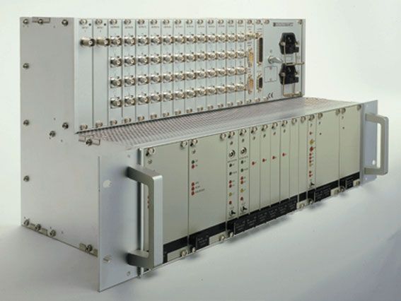
The OSA 5581C GPS-SR comes as an ETSI or 19” sub-rack. In the ETSI
version the connectors are located on the front panel, while on the 19” version
the connectors are located on the rear panel.
The physical layout of the OSA 5581C GPS-SR (ETSI version) is shown in
Figure 1.
OSA 5581C GPS-SR (ETSI version)
Board / Connector layout Management
Input Time conn.
connectors Output connectors code Power connectors
PPS
Antenna input
Auxiliary input
Time
Code
ETSI
(266mm / 10.47")
ANSI
(133mm / 5.24")
Input Section Output section Time RMU/ Power supply section
Code LMU
ANSI (483 mm / 19")
ETSI (535 mm 21.06")
Figure 1: Equipment layout of the OSA 5581C GPS-SR, ETSI version.
The above drawing shows the maximum configuration of the equipment:
2 × Input & Holdover modules for GPS signal, E1 (T1) or MHz
auxiliary input
2 × Phase Stepper Switch (PSS).
4 × Output Interface Unit (OIU).
1 × Time Code Unit (TCU) for NTP or IRIG-B time outputs.
1 × Management slot for Remote/Local Manager Unit (RMU/LMU)
2 × Power Supply Unit (PSU).
3 × Connector tiles Set (16 outputs each).
1 × Connector panel (for power supply and management).
Please refer to sections 4 and 7 for further details
Oscilloquartz SA ©2003Author: Pages:
SIPA 8 of 35
Title: File:
Booklet b81c_13.doc
Distribution: Reference:
External Rev 13 31/03/2003 SIPA
3.2 System architecture
Figure 2 shows the block diagram of the OSA 5581C GPS-SR.
OSA 5581C GPS-SR
Block Diagram
GPS-x1-Y / Phase Stepper Output Board #1 16×E1 / T1 / Frequency
E1 / T1 / Frequency Aux. Input Switch
Output Board #2 16×E1 / T1 / Frequency
Output Board #3 16×E1 / T1 / Frequency
GPS-x1-Y / Phase Stepper
E1 / T1 / Frequency Aux. Input Switch Output Board #4
48VDC / 115VAC / 220VAC Power Supply Unit Time Code / PPS
48VDC / 115VAC / 220VAC Power Supply Unit
Management bus
Remote Management Unit RS232C / 10/Base-T
Figure 2: Block diagram of the OSA 5581C GPS-SR.
The above drawing illustrates how all the critical parts in the OSA 5581C GPS-
SR are duplicated in order to obtain the highest possible reliability.
Reliability figures are given in section 5, pp. 19.
All units in the OSA 5581C GPS-SR communicate via an internal
communication bus, which forms a part of the back plane. The management
module, either MAC2-R, RMU or LMU, communicate with all other units via
this bus.
Important: Thanks to its robust design, the OSA 5581C GPS-SR is fully
operational even if the management module is faulty or removed.
Oscilloquartz SA ©2003Author: Pages:
SIPA 9 of 35
Title: File:
Booklet b81c_13.doc
Distribution: Reference:
External Rev 13 31/03/2003 SIPA
3.3 Release features overview
Table 1 below lists the major features available in the different releases of the
OSA 5581C GPS-SR.
Table 1: Features chart for the OSA 5581C GPS-SR.
Release 1.1 1.2 2.0E 2.1E 2.1T
G.812 type I, V, VI (SSU for SDH) oscillator
G.812 type II (Stratum 2) oscillator
Auxiliary Frequency input
Auxiliary E1 input
Auxiliary T1 input
Full SSM functionality (E1)
Full SSM functionality (T1)
Manageable only locally via MAC2-R module
Manageable remotely/locally via RMU/LMU
Manageable locally via LM software
Manageable remotely via LM + RAM software
Manageable remotely via SyncView™
Embedded NTP Server
Four IRIG-B outputs
Retiming of E1 traffic signals
Retiming of T1 traffic signals
Oscilloquartz SA ©2003Author: Pages:
SIPA 10 of 35
Title: File:
Booklet b81c_13.doc
Distribution: Reference:
External Rev 13 31/03/2003 SIPA
4 Theory of Operation
4.1 Input stage & Holdover capability
The OSA 5581C GPS-SR can be equipped with one or two GPS receivers,
each with an auxiliary (E1/T1/frequency) synchronisation input.
Four types of the Input & Holdover module are available.
GPS-E1-A
E1 / frequency auxiliary input, internal Rubidium oscillator
GPS-T1-A
T1 / frequency auxiliary input, internal Rubidium oscillator
GPS-E1-B
E1 / frequency auxiliary input, internal Oven-Controlled oscillator
GPS-T1-B
T1 / frequency auxiliary input, internal Oven-Controlled oscillator
GPS-x1-Y
Block Diagram
Internal com m unication
Micro
G PS engine Tracking System RS232C
Controller
Frequency & E1 / T1/ frequency
E1 / T1 / OCXO 8663 /
frequency
Auxiliary input Tim e Code 1 pps
Rubidium Tim e Code
Output
Power Supply Unit
Figure 3: Block diagram of the GPS-x1-Y Input Interface Unit (IIU).
4.1.1 Input selection
The equipment selects the active sync input according to a user-defined priority
table and the SSM4 signal if available. When input selection is based on the
SSM, the input signal with the best SSM value will be selected as the reference
sync input (whenever the two input signals have the same SSM value, the
signal with the highest priority will be selected).
The OSA 5581C management software also allows to associate a (static) SSM
value to inputs that do not carry SSM information (e.g. frequency inputs).
4
ITU-T rec. G.781 describes three SSM sets for lower bit rate traffic carrying signals in the
SDH, SONET and Japan. Oscilloquartz have based the implementation of the SSM in the IIU
on the SSM set description for SDH and SONET networks in this recommendation.
Oscilloquartz SA ©2003Author: Pages:
SIPA 11 of 35
Title: File:
Booklet b81c_13.doc
Distribution: Reference:
External Rev 13 31/03/2003 SIPA
The input selection is working in a revertive mode.5
4.1.2 Holdover capability
The Input & Holdover module is based on the Motorola UT-Oncore GPS
receiver and a holdover function provided by the internal OSA 8663 OCXO or
Rubidium oscillator. These two items provide stability and filtering
characteristics compliant to the ITU-T recommendation G.812 type I, II, V,
and VI (i.e. they fulfil the requirements for an SSU used in a SDH and SONET
network) as indicated in Table 2.
When the input module is locked to a GPS signal, the filtering function ensures
that the reference synchronisation signal fulfils ITU-T recommendation
G.8116.
Table 2: Source: ITU-T recommendation G.812 (06/98).
G.812
G.811 Annex I
Type I Type II Type III
Type IV Type V Type VI
Holdover NA 2 × 10⁻¹⁰ 1 × 10⁻¹⁰ 1 × 10⁻⁹ 4 × 10⁻⁸ 1 × 10⁻⁹ 2 × 10⁻⁸
Accuracy 1 × 10–11 NA 1.6 × 10⁻⁸ 4.6 × 10⁻⁶ 4.6 × 10⁻⁶ NA NA
Period T Lifetime NA 1 year 1 year 1 year NA NA
Pull-in NA 1 × 10⁻⁸ 1.6 × 10⁻⁸ 4.6 × 10⁻⁶ 4.6 × 10⁻⁶ ND ND
Hold-in NA NA 1.6 × 10⁻⁸ 4.6 × 10⁻⁶ 4.6 × 10⁻⁶ ND ND
Pull-out NA TBD NA NA NA ND ND
7
GPS-x1-A GPS-x1-A
GPS
Module GPS-x1-B7 GPS-x1-B GPS-x1-B GPS-x1-B
(GPS-x1-C) 8 (GPS-x1-C)8
NA Not Applicable
TBD To Be Decided
ND Not Decided
NOTE – The time period T applies after 30 days of continuous synchronised operation.
By using an internal oscillator (OSA 8663 OCXO or Rubidium), the OSA
5581C GPS-SR fulfils the above requirement for Synchronisation Supply
Units (SSU) in an SDH or SONET network.
5
Revertive: if a valid input with higher priority than the current reference returns, the
equipment will select the higher priority input as its primary reference input.
6
Please note that the U.S. DoD (Department of Defence) has set the SA (Selective
Availability) to OFF as from May 1st, 2000. At the same time the maintenance of the GPS was
transferred to DoT (Department of Transport).
In order to ensure that potential adversaries do not use GPS, the U.S. military is dedicated to
the development and deployment of regional denial capabilities in lieu of global degradation.
7
When locked to GPS signal.
8
GPS-x1-C: Stipulated input module with OSA OCXO 8741 Fulfilling ITU-T G.812 (III &
IV). Please contact your local representative or Oscilloquartz directly, for further detail and
release plan.
Oscilloquartz SA ©2003Author: Pages:
SIPA 12 of 35
Title: File:
Booklet b81c_13.doc
Distribution: Reference:
External Rev 13 31/03/2003 SIPA
4.1.3 Oscillators
The input unit can contain one of two different oscillators, depending on
the expected performance of the system. The different oscillators are:
4.1.3.1 OSA 8663 OCXO
The performance of the OSA 8663 OCXO meets or exceeds ITU-T G.812
type I, V & VI.
The long-term holdover stability9 of the OSA 8663 OCXO is:
< ± 1 × 10⁻¹⁰ / day
< ± 2 × 10⁻⁸ / year
Expected lifetime for the OSA 8663 OCXO is more than 15 years. It is
totally maintenance-free and does not require any kind of mechanical
adjustment.
4.1.3.2 OSA Rubidium oscillator
The performance of the OSA Rubidium oscillator meets or exceeds ITU-T
G.812 type II.
The long-term holdover stability10 of the OSA Rubidium oscillator is:
< ± 5 × 10-11 / month
< ± 5 × 10⁻¹⁰ / year
The frequency stability is:
< 5 × 10⁻¹⁰ / day peak-to-peak (-5°C - +55°C)
Expected lifetime for the OSA Rubidium oscillator is more than 7 years. It
is totally maintenance-free and does not require any kind of mechanical
adjustment.
4.1.4 GPS antenna system
The GPS module kit for the OSA 5581C GPS-SR is delivered with a
standard antenna with mounting accessories, EMP protection kit and 10m
interconnection cable (between antenna and EMP protection).
The remaining antenna cable (between EMP protection and equipment) has
to be ordered separately. The antenna cable is available in length of 20m
(RG58), 60m (RG213), and 120m (2 × RG213 [60m] with line amplifier).
For lengths longer than 120 meters Oscilloquartz proposes the CellFlex
cable, which can be ordered in exact lengths up to 300 meters.
Please contact Oscilloquartz if other requirements exist.
Figure 4 shows the principle for the GPS antenna installation.
9
Typical values after 30 days of continuous operation.
10
Typical values after 60 days of continuous operation.
Oscilloquartz SA ©2003Author: Pages:
SIPA 13 of 35
Title: File:
Booklet b81c_13.doc
Distribution: Reference:
External Rev 13 31/03/2003 SIPA
External wall
10m intercon-
nection cable
Lightning Optional
kit Oscilloquartz
20m (RG58) / Line 20m (RG58) / GPS
60m (RG213) amplifier 60m (RG213) unit
Figure 4: GPS antenna installation diagram.
4.2 Phase Stepper Switch
The Phase Stepper Switch (PSS) keeps the output signal from the standby
GPS module in phase with that of the active GPS module.
4.2.1 Phase build-out
When the equipment changes reference, it will go into holdover for a short
period of time (2 seconds) in order to provide a constant synchronisation
signal to the output units.
Although the two inputs from the two GPS modules have the same
frequency, they still can vary in phase [φ] (as shown in Figure 5). The
result would be that, when switching between the two inputs, the
synchronisation output would be affected by a phase jump, as shown in the
figure (dotted line).
In the OSA 5581C GPS-SR Oscilloquartz has eliminated this phase jump
by adjusting the phase of the “new” reference signal during an extended
holdover period (additional 20 seconds). During this period, the element
calculates a phase build-out constant that is used to align the phase of the
reference with the phase of the internal holdover oscillator (as shown in
Figure 5).
Oscilloquartz SA ©2003Author: Pages:
SIPA 14 of 35
Title: File:
Booklet b81c_13.doc
Distribution: Reference:
External Rev 13 31/03/2003 SIPA
Phase Buildout
Phase [φ]
Sync Input 2
Phase
buildout
[∆φ]
Sync Input 1
Time [s]
20s
Output w/o 2s
phase buildout
Output w/ Provided by internal oscillator
phase buildout
Figure 5: Schematic presentation of the phase buildout.
4.3 Synchronisation outputs
The OSA 5581C GPS-SR can be equipped with up to four Output Interface
Units (OIUs) each providing 16 synchronisation output signals. Hence the
OSA 5581C GPS-SR provides the following capacity of protected and
unprotected outputs11:
32 1+1 protected outputs (requires 4 OIUs)
16 1+1 protected and 32 unprotected outputs (requires 4 OIUs)
48 unprotected outputs (requires only 3 OIUs)12
The OSA 5581C GPS-SR can of course be equipped with only one or two
OIUs, if fewer outputs are needed.
All outputs from the OSA 5581C GPS-SR can be individually squelched by
operator commands via the management software. The default condition is
for all outputs to be active.
The OSA 5581C GPS-SR also supports conditional squelching where the
operator can set the condition under which the outputs are squelched.
Conditional squelching is possible for the following conditions:
During the warm-up phase
(configurable squelching period)
After a configurable delay after entering holdover mode
(configurable period before and after squelch)
When SSM mode is enabled, the OSA 5581C GPS provides SSM
information on its E1/T1 outputs according to ITU-T G.781 specification.
This information consists of the SSM value of the currently selected input
or, if the equipment is in holdover, the SSM value corresponding to the
holdover quality of the fitted oscillator.
11
RTU modules can not be used in protected mode.
12
In this configuration, the 4th OIU can not be used due to physical constrains in the connector
area
Oscilloquartz SA ©2003Author: Pages:
SIPA 15 of 35
Title: File:
Booklet b81c_13.doc
Distribution: Reference:
External Rev 13 31/03/2003 SIPA
4.4 Re-Timing Unit (RTU)
A Re-Timing Unit (RTU) synchronises a traffic signal based upon the
synchronisation signal from the OSA 5581C GPS-SR. Each channel in the
RTU has a re-timing buffer holding two traffic frames. Each RTU provides
retiming of up to 8 channels.
If the re-timing buffer overflows, controlled slips are applied to the traffic
signals. Slips caused in the internal buffer can be monitored by suitably
configuring alarm thresholds via the Local Manager or the SyncView™
Management software. Slip thresholds can be set in terms of slips per hour,
day or week on an individual channel basis.
The RTU takes up one of the slots utilised for an Output Interface Unit.
Important: To ensure that traffic is not lost due to RTU card removal,
card fault or loss of power in the equipment, the traffic signals are passed
through the by-pass relays situated in the RTU connector tile set.
RETIMING UNIT RTU CONNECTOR TILE
BYPASS
CONNECTORS
RELAYS
SYNC. TRAFFIC INPUT
INPUT RETIMING
FUNCTION
TRAFFIC OUTPUT
TRAFFIC INPUT
RETIMING
FUNCTION
TRAFFIC OUTPUT
TRAFFIC INPUT
RETIMING
FUNCTION
TRAFFIC OUTPUT
TRAFFIC INPUT
RETIMING
FUNCTION
TRAFFIC OUTPUT
TRAFFIC INPUT
RETIMING
FUNCTION
TRAFFIC OUTPUT
TRAFFIC INPUT
RETIMING
FUNCTION
TRAFFIC OUTPUT
TRAFFIC INPUT
RETIMING
FUNCTION
TRAFFIC OUTPUT
MICRO-
CONTR. TRAFFIC INPUT
RETIMING
FUNCTION
TRAFFIC OUTPUT
BYPASS CONTROL
Figure 6: Block diagram of the Re-Timing Unit.
4.5 Output Connectors
Several output connector types are available. Output impedance can be
either unbalanced (75Ω) or balanced (100Ω for T1 outputs, 133Ω for
64kbit/s cc outputs, 120Ω for all other output types). Field-exchangeable
Output Connector Tiles determine the output connector type and output
impedance.
RTU cards require specially designed connector tiles, which includes by-
pass relays in case of unit failure.
Oscilloquartz SA ©2003Author: Pages:
SIPA 16 of 35
Title: File:
Booklet b81c_13.doc
Distribution: Reference:
External Rev 13 31/03/2003 SIPA
4.6 Time Code Units (TCU)
4.6.1 Embedded NTP Server
The TCU-NTP module provides an embedded NTP (Network Time
Protocol) Stratum 1 server functionality without having to provision and
maintain a separate GPS receiver with antenna, cabling and management
connection. Moreover, time information is kept even in case of loss of the
GPS signal, that is, when the system is locked on an auxiliary input or
when it is in holdover, with the accuracy of the active reference.
4.6.2 IRIG-B Outputs
The TCU-IRIG-B module provides four IRIG-B outputs as follows:
2 x IRIG-B code 122 (AM 1kHz)
2 x IRIG-B code 012 (ACMOS, pulse width coded)
Similarly to the TCU-NTP module, time information is kept even in case
of loss of the GPS signal, that is, when the system is locked on an auxiliary
input or when it is in holdover, with the accuracy of the active reference.
4.7 Management unit (MAC / RMU /LMU) and connection
The management unit (Monitoring and Alarms Controller [MAC], Remote
Manager Unit [RMU] or Local Management Unit [LMU]) concentrates the
alarms from all modules within the OSA 5581C GPS-SR and provides
management connection(s) to the equipment. These units provide front
panel LED indications, relay contact outputs for in-station monitoring, and
an RS-232C port for external control using the Local Manager (LM for
5581C) software. LM software provides an user-friendly, graphical
interface running on any IBM compatible computer equipped with MS
Windows 98 / NT / 2000 / XP operating system. RMU additionally
provides a connection to the SyncView™ synchronisation management
system via a TCP/IP connection.
It is worth mentioning that failure or removal of the management unit will
eliminate only the management functions provided by the unit itself,
without affecting synchronisation in any way. For example, protection
switching and input selection processes will still be ensured, as well as all
the selected synchronisation outputs will still be active, with the same
quality as before.
4.7.1 Remote Monitoring via Modem
The OSA 5581C GPS-SR can be supervised/managed in three different
manners, using either the MAC, LMU or RMU management unit:
Locally using LM for 5581C (MAC, LMU and RMU)
Remotely using LM for 5581C and RAM (MAC, LMU and RMU)
This solution connects the LM to the management unit via a dial-up
connection provided via telephone line or a LAN / WAN.
(Please refer to the RAM data sheet for more information on this
solution)
Oscilloquartz SA ©2003Author: Pages:
SIPA 17 of 35
Title: File:
Booklet b81c_13.doc
Distribution: Reference:
External Rev 13 31/03/2003 SIPA
Remotely using SyncView™ (RMU only)
The OSA 5581C GPS-SR can be managed from SyncView™, the
Synchronisation Management System from Oscilloquartz through a
TCP/IP network using the RMU management unit.
(Please refer to the SyncView™ Booklet for further details)
4.8 Power Supply
The Power Supply Units (PSUs) 1 and 2 operate in a 1:1 hot standby
protection mode. Failure or removal of one PSU has no effect on the
synchronisation outputs of the OSA 5581C GPS-SR.
The OSA 5581C GPS-SR accepts 48VDC, 115VAC, or 220VAC in any
combination.
4.9 Cover Plates
All non-equipped slots in the OSA 5581C GPS-SR must be fitted with
cover plates for mechanical protection and for compliance with the
relevant EMC and safety norms.
4.10 Configuration
All plug-in modules in the OSA 5581C GPS-SR are hot-pluggable i.e. can
be replaced while the equipment is in use. The passive splitters and
combiners are permanently fixed to the back plane for maximum security.
The table below shows an example of minimal configuration of the OSA
5581C GPS-SR.
Table 3: Minimal configuration of the OSA 5581C GPS-SR.
Quantity Module
1 GPS-x1-Y (GPS input & holdover module)
1 PSS Bypass
1 OIU
1 OIU connectors Tile Set
1 PSU
1 PSU connector set
1 LMU
N Cover plates to fill empty card and
connector tile slots13
4.11 Passive Timing Extractor (TEX-P)
Signals from non-terminated E1 / T1 links can be connected to the OSA
5581C GPS-SR using an external TEX-P. The TEX-P is a passive in-line
device, normally mounted externally to the equipment, that taps off a
13
Needed for EMC and safety reason.
Oscilloquartz SA ©2003Author: Pages:
SIPA 18 of 35
Title: File:
Booklet b81c_13.doc
Distribution: Reference:
External Rev 13 31/03/2003 SIPA
portion of the digital signal without interfering with traffic or degrading
the link in any way. One TEX-P handles up to two separate E1 / T1 feeds.
OSA TEX-P
2 x 2.048Mbit/s 1
feeds with traffic Switch
2
2.048MHz
outputs
OSA 5581C Cross
GPS-SR Connect
SDH
MUX
Figure 7: Typical use of the TEX-P with the OSA 5581C GPS-SR.
4.12 Impedance Adapter
Oscilloquartz supplies two kind of adapters, which both can be fitted to the
equipment connectors.
Impedance matching between 120Ω and 75Ω (Balun),
Impedance matching between 75Ω and 50Ω.
Please refer to sections 7 for further details.
Oscilloquartz SA ©2003Author: Pages:
SIPA 19 of 35
Title: File:
Booklet b81c_13.doc
Distribution: Reference:
External Rev 13 31/03/2003 SIPA
5 Reliability
5.1 Method
The MTBF figures given in Table 4 were calculated according to MIL HDBK
217F1.0. The MTBF and availability values for the complete equipment were
derived from these MTBF figures of the Table and the following assumptions:
The failure rates λi of the modules is constant.
MTTR is independent of time and of the number of modules to be
repaired, its value is 3 days.
The availability is constant (stationary condition).
There is no down-time during repair of redundant modules.
The MTBF values of the complete equipment reflect the mean time between
failures of the synchronisation function, i.e. the function of receiving and
selecting an input reference, regenerating it or generating a local frequency in
case of holdover mode, and distributing the output synchronisation signal to the
equipment’s outputs. The MTBF is calculated for the total failure of this
synchronisation function. However, the system MTBF value does not account
for failures of the equipment management function, since the latter has no
influence on the integrity of the synchronisation function.
5.2 Reference Configuration
The calculations of MTBF and availability are based on the following
reference configuration:
2×GPS-E1-B in hot redundancy
2×PSS
2×OIU-6 in hot redundancy
2×PSU-48VDC in hot redundancy
The reliability diagram of the reference configuration is given in Figure 8. In
this diagram, the availability of the two input signals is assumed to be equal
to 1. Protection of the OIUs can be obtained in two ways:
Use an OIU pair in protected operating mode
Use two unprotected OIUs and combine the two unprotected signals
in the equipment they are connected to.
Oscilloquartz SA ©2003Author: Pages:
SIPA 20 of 35
Title: File:
Booklet b81c_13.doc
Distribution: Reference:
External Rev 13 31/03/2003 SIPA
Table 4: MTBF figures of individual modules
Module MTBF Module MTBF
[h] [h]
GPS-E1-A (incl. antenna) 134,300 GPS-E1-B (incl. antenna) 134,300
GPS-T1-A (incl. antenna) 134,300 GPS-T1-B (incl. antenna) 134,300
PSS 96,000 PSS-Bypass 15,000,000
OIU-CC 45,000 RTU-T1 183,600
OIU-2 86,000 RTU-E1 183,600
OIU-6 86,000 PSU-115VAC 359,500
OIU-10 90,000 PSU-230VAC 398,400
OIU-5 MHz 90,000 PSU-48VDC 398,400
OIU-10 MHz 90,000 MACR-2 114,000
TEX-P 10,320,000 RMU 114,000
14
Combiner/Splitter 15,000,000
GPS-
PSU PSS OIU
x1-B
Passive
Combiner/
Splitter
GPS-
PSU PSS OIU
x1-B
Figure 8: Reliability diagram of the reference configuration.
5.3 Reliability Calculations
MTTR = 3days = 72hours
1
µ=
MTTR
1
λi = , For i = GPS, PSS, OIU, PSU, and CS15
MTBFi
(λGPS )2 (λ PSS )2
λ1 = 2 × λ2 = 2 ×
µ µ
14
Passive component on the wiring backplane
15
CS = Combiner / Splitter
GPS = GPS Module GPS-x1-Y
PSS = Phase Stepper Switch
PSU = Power Supply Unit
OIU = Output Interface Unit
Oscilloquartz SA ©2003Author: Pages:
SIPA 21 of 35
Title: File:
Booklet b81c_13.doc
Distribution: Reference:
External Rev 13 31/03/2003 SIPA
(λOIU )2 (λ PSU )2
λ3 = 2 × λ4 = 2 ×
µ µ
1
MTBF =
λ1 + λ2 + λ3 + λ4 + λCS
MTBF
Availability =
MTBF + MTTR
Results:
MTBF = 9,225,300 hours = 1,037 years
Availability = 0.999992
Oscilloquartz SA ©2003Author: Pages:
SIPA 22 of 35
Title: File:
Booklet b81c_13.doc
Distribution: Reference:
External Rev 13 31/03/2003 SIPA
6 Technical data
All values are given at +25oC unless otherwise stated
6.1 Input / Hold-Over section16
Table 5: Technical data for the input and Hold-over section.
INPUT INTERFACE UNITS
(Auxiliary inputs compiles to relevant sections in ITU-T G.703 & G.704)
• GPS signal,
• L1 1575.42 MHz
• External gain 11dB to 33 dB
• Simultaneous tracking of up to 8 satellites
• Electrical,
• GPS-E1-B: 2.048Mbit/s (E1), HDB3 coded; 75Ω
unbalanced (120Ω balanced via TEX-P or Balun)
• GPS-T1-B: 1.544Mbps (T1) 75Ω unbalanced (100Ω
balanced via TEX-P or Balun)
• Frequency
• Input: 64kHz, 1, 1.544, 2.048, 5, or 10MHz.
• Automatic detection of input frequency
Input Characteristics17
• Sine wave input level: 0.3 to 1.5Vrms
• Square wave input level: 1 to 5Vpp
• 75Ω (120Ω via external Balun - not included)
• SSM values
• Extracted from incoming 2.048 Mbit/s (E1) and 1.544
Mbit/s (T1) input signals as per ITU-T G.781
recommendation
• A static SSM value can be assigned via management
software to every input signal that does not carry SSM
information
• Valid (i.e. locked) GPS inputs are assigned a PRC/PRS
SSM quality
Detection of the following criteria causes input changeover:
For GPS-E1-B input module:
Input Qualification LOS, LFA, AIS, ER
For GPS-T1-B input module:
LOS, COFA, AIS (Blue Alarm).
INPUT SELECTION
Input validation criteria depend on input signal type.
Input Validation
See section on Input Interface Units - Input Qualification.
Three possible input selection modes exist:
• Automatic, based on user-defined priority table
Input Selection • Automatic, based on SSM and user-defined priority
table
• Manual
Phase build-out function cancels phase offsets between
Max. Output Phase Change after inputs.
Input Changeover Output phase change: typically < 10ns; exact value depends
on environmental conditions.
16
The OSA 5581C GPS-SR accepts one or two Holdover sections/GPS modules.
17
Unterminated E1/T1 input requires externally mounted TEX-P
Oscilloquartz SA ©2003Author: Pages:
SIPA 23 of 35
Title: File:
Booklet b81c_13.doc
Distribution: Reference:
External Rev 13 31/03/2003 SIPA
TRACKING SUBSYSTEM
Digital Phase Locked Loop (D-PLL). Incorporated in the
Type
GPS-x1-Y Input Interface Unit (IIU).
Exceeds ITU-T G.812 Type I, II, V, and VI.
Filter bandwidth: 20µHz to 20mHz, user
Jitter & Wander Filtering
programmable via the
Characteristics
management software.
Gain peaking: < 0.2dB
Variable between 100 and 100,000 seconds (corresponds to
filter bandwidth between 20µHz and 20mHz) to optimise
Loop Time Constant (τ) filtering characteristics; programmable via the management
software.
Optimal value for GPS-x1-Y input module: 2’000s
Observation Period: TDEV:
0.1s < τ ≤ 100s 3 ns
Noise Generation 100s < τ ≤ 1’000s 0.03 * τ ns
(Ideal input signal, or GPS locked, 1’000s < τ ≤ 10’000s 30 ns
constant temperature) Observation Period: MTIE:
0.1s < τ ≤ 1’000s 0.275 × 10⁻³ τ + 0.025µs
1’000s < τ 1×10⁻⁵ τ + 0.29µs
HOLDOVER OSCILLATOR18 (OCXO 8663 B6SG)
Frequency Stability < ±2.0 × 10⁻¹² /day (when locked to GPS)
< ±1.0 × 10⁻¹⁰/day*
Holdover Stability (at 25°C) < ±2.0 × 10⁻⁸/year
*After 30 days of continuous operation
Stability vs. Temperature < ±6.0 × 10⁻¹⁰ pp (-5°C to +55°C)
Initial Frequency Offset at Entry
< 1.5×10⁻¹¹
into Holdover Mode
Short Term Stability (Bw=1kHz) < 1.5×10⁻¹¹ (0.2s – 10s)
Pulling Range (peak to peak) > 6 × 10⁻⁷
Observation Period: TDEV (ns):
0.1s < τ ≤ 25s 3
25s < τ ≤ 100 s 0.12 * τ
100s < τ ≤ 10’000 s 12
Noise Generation
Observation Period: MTIE (µs):
(when in Hold-over mode,
constant temperature) 0.1s < τ ≤ 7.5s 0.75
7.5s < τ ≤ 20s 0.1 * τ
20s < τ ≤ 400s 2
400s < τ ≤ 1’000s 0.005 * τ
1’000s < τ ≤ 10’000s 5
In-service adjustments None required
Life time > 15 years
18
Please refer to Table 2, page 11, for compliance to ITU recommendations.
Oscilloquartz SA ©2003Author: Pages:
SIPA 24 of 35
Title: File:
Booklet b81c_13.doc
Distribution: Reference:
External Rev 13 31/03/2003 SIPA
HOLDOVER OSCILLATOR18 (Rubidium oscillator)
Frequency Stability < ±2.0 × 10⁻¹² /day (when locked to GPS)
< ±5.0 × 10⁻¹¹ / month**
Holdover Stability (at 25°C) < ±5.0 × 10⁻¹⁰ / year
** after three months of continuous operation
Stability vs. Temperature < ±1.0 × 10⁻¹⁰ pp (-5°C - +55°C)
Initial Frequency Offset at Entry
4.58× 10⁻¹³ (theoretical value)
into Holdover Mode
3 × 10-11 / 1 second
Short Term Stability 1 × 10-11 / 10 second
3 × 10-12 / 100 second
Pulling Range (peak to peak) > 3 × 10⁻⁸ (G.812 type I compliant)
Observation Period: TDEV (ns):
0.1s < τ ≤ 25s 3.2 * τ -0.5
25s < τ ≤ 40 s 2
Noise Generation
40s < τ ≤ 1’000 s 0.32 * τ 0.5
(when in Hold-over mode,
1’000s < τ 10
constant temperature)
Observation Period: MTIE (µs):
0.05s < τ ≤ 280s 0.3 + 0.002’5τ
280s < τ 0.997 + 0.000’01τ
In-service adjustments None required
Life time > 7 years
Oscilloquartz SA ©2003Author: Pages:
SIPA 25 of 35
Title: File:
Booklet b81c_13.doc
Distribution: Reference:
External Rev 13 31/03/2003 SIPA
6.2 Output section
Table 6: Technical data for the output section.
OUTPUT INTERFACE UNITS (OIUs) & RE-TIMING UNITS (RTUs)
(OIU & RTU types compiles to relevant sections in ITU-T G.703 & G.704)
OSA 5581C GPS-SR accepts up to 4 Output Interface Units
(OIU) or 3 Re-Timing Units (RTU).
Number of Slots
• Each OIU provides 16 outputs.
• Each RTU provides re-timing of 8 traffic channels.
OIU-CC: 16 outputs 64kbit/s composite clock
OIU-2: 16 outputs 1.544Mbit/s
OIU-10: 16 outputs 2.048MHz
OIU Types
OIU-6: 16 outputs 2.048Mbit/s
OIU-5MHz: 16 outputs 5MHz
OIU-10MHz: 16 outputs 10MHz
RTU-T1: 8 channels 1.544Mbit/s (T1)
RTU Types
RTU-E1: 8 channels 2.048Mbit/s (E1)
Other OIU/RTU Types Please contact factory for other OIU types.
Frequency 1 PPS
Duration: 200ms¨
1 PPS (Pulse-Per-Second) Polarity: True
specifications Level/Impedance: ACMOS 2.5 Vpp / 39 ohms serial
resistor
Connector type: BNC
Unbalanced ports: BNC or BT 43
Connectors19 Balanced ports: 9 pins Sub-D type or BNO
Selection determinant by OIU Connector Tiles
Squelch mask: Outputs can be squelched via a squelch
mask under operator control on a per output basis. Squelch
mask is set via the management software.
Conditional squelch can be configured for special
Output Squelching situations. Conditional squelch is programmable for
following conditions:
• During the warm-up phase
• After a configurable delay after entering holdover
mode.
19
The output connector tiles that are specified at the time of order determine required
impedance.
Oscilloquartz SA ©2003Author: Pages:
SIPA 26 of 35
Title: File:
Booklet b81c_13.doc
Distribution: Reference:
External Rev 13 31/03/2003 SIPA
6.3 Management section
Table 7: Technical data for the Management Section.
MONITORING & ALARMS CONTROLLER (MAC2-R)
Local Terminal Port RS-232C on 9 pins Sub-D type connector
Protocol TTY.
Communications Parameters 9600 baud, 8 bits, 2 stop bits, parity: none.
Non-volatile memory stores 128 events with date and time
Event Log
stamp on a FIFO (First in First Out) basis.
Events & alarms are reported spontaneously to the RS-232C port,
Status Reporting
to be presented in the management software.
Fully automatic inventory for all replaceable modules and the
Shelf Inventory
sub-rack itself.
LED indicators are provided on the front panels of all modules.
The following summaries of shelf alarms are provided on
MAC2-R front panel:
• General Alarm
• Critical
Alarms • Major
• Minor
• Warning
• Urgent
• Non-urgent
• Receiving Attention (LED and toggle switch)
8 relay contacts
Electrical Outputs (Imax=250mA; Vmax = 50V; Pmax = 3W).
Contacts available from a 25 pins Sub-D type connector.
Alarm masks settable for each alarm output via the
Alarm Output Masks
management software.
Oscilloquartz SA ©2003Author: Pages:
SIPA 27 of 35
Title: File:
Booklet b81c_13.doc
Distribution: Reference:
External Rev 13 31/03/2003 SIPA
REMOTE MANAGER UNIT (RMU)
Local management port RS-232C on 9 pins Sub-D type connector
Protocol on Local mngt Port MML Language on RS232C serial communication
Remote management port Ethernet on RJ-45 type connector
Protocol on Remote mngt port MML Language on TCP/IP protocol
Shelf inventory Fully automatic inventory for all replaceable modules
LED indicators are provided on the front panels of all
modules.
The following summaries of shelf alarms are provided on
RMU front panel:
General Alarm
Critical
Alarms
Major
Minor
Warning
Urgent
Non-urgent
Receiving Attention (LED and toggle switch)
8 relay contacts
Electrical Outputs (Imax=250mA; Vmax = 50V; P max = 3W).
Contacts available from a 25 pins Sub-D type connector.
Alarm masks settable for alarms/events at display in the
Alarm Output Masks
management software.
Events & alarms are reported spontaneously to the LED and the
Status Reporting local & remote management port to be presented in the
management software.
Non-volatile memory stores 128 events with date and time
Event Log
stamp on a FIFO (First in First Out) basis.
Oscilloquartz SA ©2003Author: Pages:
SIPA 28 of 35
Title: File:
Booklet b81c_13.doc
Distribution: Reference:
External Rev 13 31/03/2003 SIPA
6.4 Physical data
Table 8: Physical data for the OSA 5581C GPS-SR.
POWER SUPPLIES Unit (PSU)
Configuration Duplicated PSUs in 1+1 hot standby protection
36 – 72 VDC floating input, or
Input Voltages 65 – 132VAC, or
150 – 265VAC
Power Consumption
< 70W during Warm-up
(Max. value; actual values depend on
< 60W during steady state
configuration)
~10 minutes before available outputs
Warm-up
~24 hours before full specification are obtained20
ENVIRONMENTAL
Storage Temperature According to ETS 300 019-2.1, Class 1.1
Transport Temperature According to ETS 300 019-2.2, Class 2.2
Operating Temperature Range According to ETS 300 019-2.3, Class 3.2
Humidity 5 – 95% non-condensing.
EMC & SAFETY - CE Mark
Certified to EN50081-1 and EN50082-1 & EN50082-2
EMC
Susceptibility to IEC 801 parts 2, 3, 4, 5 and 6
Safety Conforming to EN61010-1 and EN60950
MECHANICAL
Mounting ETSI ETS 300-119 300mm or 19" rack mount.
ETSI 6U: 266 x 535 x 240mm
Size (10.47 x 21.06 x 9.45in.)
H×W×D 19" 3U: 133 x 483 x 270mm
(5.24 x 19 x 10.63in.)
ETSI version: Front access
Connector Access
19” version: Rear access.
WEIGHT
~ 9kg (20 lbs) excluding cables & packing.
20
Need at least four visual GPS satellites for the first 24 hours.
Oscilloquartz SA ©2003Author: Pages:
SIPA 29 of 35
Title: File:
Booklet b81c_13.doc
Distribution: Reference:
External Rev 13 31/03/2003 SIPA
6.5 External passive timing extraction unit (TEX-P)
Table 9: Technical data for the External Passive Timing Extraction Unit (TEX-P).
EXTERNAL PASSIVE TIMING EXTRACTION UNIT (TEX-P)
Number of circuits Two independent circuits
Attenuation between ports
≤ 0.5dB, 0.1 ≤ f ≤ 3MHz
“Data line IN” & “Data line OUT”
Attenuation between ports
18dB ± 1dB, 0.1 ≤ f ≤ 3MHz
“Data line IN” & “Signal OUT”
Impedance of ports
75Ω unbalanced or 120Ω balanced
“Data line IN/OUT”
Impedance of ports “Signal OUT” 75Ω unbalanced
Return loss of ports “Data line IN”
≤ -20dB, 0.1 ≤ f ≤ 3MHz
(75 Ω) & “Signal OUT”
Ports “Data line IN/OUT”: Solder Tags
Connectors
Ports “Signal OUT”: CEI 1.5/5.6 coax connectors.
Dimensions (H×W×D) 112×43.1×64.5mm (4.41×1.70×2.54in)
Oscilloquartz SA ©2003Author: Pages:
SIPA 30 of 35
Title: File:
Booklet b81c_13.doc
Distribution: Reference:
External Rev 13 31/03/2003 SIPA
7 Summary of OSA 5581C GPS-SR parts
Table 10: Summary of OSA 5581C GPS-SR parts.
Name
Sub-rack
ETSI/6U Mainframe for OSA 5581C, CE approved
Delivered with:
1x Operating and Technical Manual on CD-ROM
1x Set of standard accessories,
Packing included
19”/3U Mainframe for OSA 5581C, CE approved
Delivered with:
1x Operating and Technical Manual on CD-ROM
1x Set of standard accessories,
Packing included
Input & Holdover Unit (width 12TE)
GPS-E1-A Kit, including:
• GPS-E1-A module with Rubidium Oscillator
• Antenna
• Lightning protection kit, including
EMP protector
Capsule
• 10m interconnection cable
GPS-T1-A Kit, including:
• GPS-T1-A module with Rubidium Oscillator
• Antenna
• Lightning protection kit, including
EMP protector
Capsule
• 10m interconnection cable
GPS-E1-B Kit, including:
• GPS-E1-B module with OCXO 8663
• Antenna
• Lightning protection kit, including
EMP protector
Capsule
• 10m interconnection cable
GPS-T1-B Kit, including:
• GPS-T1-B module with OCXO 8663
• Antenna
• Lightning protection kit, including
EMP protector
Capsule
• 10m interconnection cable
Phased Stepper Switch Section (width 4TE)
PSS Bypass Board
PSS Phase Stepper Switch
Output Interface Unit (width 4TE)
OIU-CC 16 outputs 64Kbit/s c/c
OIU-2 16 outputs 1.544Mbit/s
OIU-6 16 outputs 2.048Mbit/s
OIU-10 16 outputs 2.048MHz
Oscilloquartz SA ©2003Author: Pages:
SIPA 31 of 35
Title: File:
Booklet b81c_13.doc
Distribution: Reference:
External Rev 13 31/03/2003 SIPA
OIU-1.544MHz 16 outputs 1.544MHz
OIU-5MHz, 16 outputs, 1Vrms
OIU-10MHz, 16 outputs, 1Vrms
Output Interface Unit (width 4TE)
OIU Connector Tile Set 16 x 50Ω/BNC connector
OIU Connector Tile Set 16 x 75Ω/BNC connector
OIU Connector Tile Set 16 x 75Ω /BT43
OIU Connector Tile Set 16 x 75Ω / CEI 1.0/2.3
OIU Connector Tile Set 16 x 75Ω / CEI 1.0/2.3 (only for 64 outputs)
OIU Connector Tile Set 16 x 75Ω / CEI 1.6/5.6
OIU Connector Tile Set 16 x 75Ω / CEI 1.6/5.6 (only for 64 outputs)
OIU Connector Tile Set 16 x 100Ω / BNO connector
OIU Connector Tile Set 16 x 100Ω, Balanced Sub-D, 9p two output per connector
OIU Connector Tile Set 16 x 120Ω Balanced/Sub-D, 9p two outputs per connector.
OIU Connector Tile Set 16 x 133Ω / BNO connector
Re-Timing Unit (width 4TE)
RTU-T1, 8 channels, 1.544Mbit/s
RTU-E1, 8 channels, 2.048Mbit/s
RTU Connector Tile Set for RTU-E1 75Ω, BNC, 8 channels in-out
RTU Connector Tile Set for RTU-T1 100Ω, Sub-D 9p, 8 channels in-out
RTU Connector Tile Set for RTU-E1 120Ω Balanced, Sub-D 9p, 8 channels in-out
Time Code Module (width: 8TE)
NTP, Time Code Unit
Management Module (width: 4TE)
MAC2-R Management Unit with Urgent/Non-Urgent Alarms
RS 232 Interface and Relay outputs
MAC2-R (Option A) Management Unit with Urgent/Non-Urgent Alarms
RS 232 Interface and Relay outputs inverted.
RMU Management Unit with Urgent/Non-Urgent Alarms
RS 232 Interface and Relay outputs inverted. TCP/IP connection to SyncView©
RMU (Option A) Management Unit with Urgent/Non-Urgent Alarms
RS 232 Interface and Relay outputs. TCP/IP connection to SyncView©
Local Manager for the OSA 5581C GPS-SR
Software & User guide on CD-ROM for Windows 95/98/NT
Power Supply Units (width: 12TE)
Power Supply Unit DC/DC (36-72VDC), 75W
Power Supply Unit AC/DC (65 – 132VAC), 75W
Power Supply Unit AC/DC (150 – 265VAC), 75W
PSU Panel with 1×DC & 1×AC connectors
PSU Panel with 2× AC connectors
PSU Panel with 2×DC connectors
Cover Plates
Cover Plate 4TE
Cover Plate 8TE
Cover Plate 12TE
OIU/RTU Dummy Tiles (Set of 4x4TE tiles)
Accessories
Oscilloquartz SA ©2003Author: Pages:
SIPA 32 of 35
Title: File:
Booklet b81c_13.doc
Distribution: Reference:
External Rev 13 31/03/2003 SIPA
Balun: 120Ω /75Ω with Krone Connector for 120Ω-end, BNC Connector for 75Ω-end
TEX-P, 2 Way Passive Timing Extractor (CEI 1.5/5.6)
Antenna for GPS-x1-B with mounting kit (without cable)
GPS-E1-B with OCXO 8663 (module only)
GPS-T1-B with OCXO 8663 (module only)
GPS CellFlex cable valid for lengths up to 300m. (order per 1m)
Includes 2×terminating N-connectors
Please specify exact length
GPS antenna cable – RG58 (20m)
GPS antenna cable – RG213 (60m)
GPS Line Amplifier (for cable length up to 60m + 60m)
GPS Lightning Protection Kit, including
• EMP protector
• Capsule
Surge Arrester Capsule
Accessory kit for 5581C
Operating Manual for 5581C ETSI, Printed
Technical Documentation on CD-ROM for OSA 5581C GPS-SR
Oscilloquartz SA ©2003You can also read