Overview and Future Advanced Engineering Applications for Morphing Surfaces by Shape Memory Alloy Materials
←
→
Page content transcription
If your browser does not render page correctly, please read the page content below

materials
Review
Overview and Future Advanced Engineering
Applications for Morphing Surfaces by Shape
Memory Alloy Materials
Andrea Sellitto *       and Aniello Riccio
 Department of Engineering, University of Campania “Luigi Vanvitelli”, 81031 Aversa (CE), Italy;
 aniello.riccio@unicampania.it
 * Correspondence: andrea.sellitto@unicampania.it; Tel.: +39-081-501-0407

 Received: 29 January 2019; Accepted: 25 February 2019; Published: 28 February 2019

 Abstract: The development of structures able to autonomously change their characteristics in response
 to an external simulation is considered a promising research field. Indeed, these structures, called
 smart structures, can be adopted to improve the aerodynamic performance of air and land vehicles.
 In this work, an overview and future applications of Shape Memory Alloys (SMA)-based smart
 structures are presented. The use of SMA materials seems to be very promising in several engineering
 sectors. Advanced SMA-based devices, designed to improve the aerodynamic performance of
 vehicles by modifying the shape of the spoiler and the rear upper panel, are briefly introduced
 and discussed in this paper. Indeed, a simplified model simulating the SMA mechanical behavior
 has been considered to demonstrate the feasibility of the introduced smart structures for adaptive
 aerodynamic applications. Numerical simulations of the investigated structures are provided as a
 justification of the proposed designs.

 Keywords: shape memory alloy; smart structure; preliminary design

1. Introduction
     The continuously increasing requirements of structures capable of autonomously adapting their
shape according to specific varying conditions has led to an increase, in the last few decades, of research
studies on morphing technologies. Such technologies are particularly suitable in the aeronautical and
automotive fields, where adaptive structures including the development of morphing skin could be
employed [1–3].
     The morphing mechanism can be realized by using smart materials, such as Shape Memory Alloys
(SMA), and piezoelectric materials able to modify the shape of the morphing component [4–6]. Among
the smart materials, SMA are able to recover their initial shape after a deformation has occurred, when
subjected to particular thermal conditions [7–9]. Moreover, they are characterized by superelastic
behavior and a high power-to-weight ratio, which make them particularly suitable for the design of
adaptive structures [10]. Several applications related to the adoption of SMA as actuators [11–21],
in both the automotive [22–27] and aerospace [28–42] fields, can be found, even if application on a large
scale is still far from being achieved. However, SMA-based actuation systems are being extensively
investigated in the framework of several research studies in order to reduce the complexity, with a
consequent reduction of weight, of the traditional electric and hydraulic actuation systems [18,43,44].
Indeed, several mechanisms based on SMA actuators are already in use, especially in the sectors of
valves and drives, where millions of devices are sold every year [45].
     In this work, an overview of smart structures based on SMA actuators is given, together with a
preliminary feasibility study on SMA-based actuation devices of vehicle control surfaces. The SMA

Materials 2019, 12, 708; doi:10.3390/ma12050708                               www.mdpi.com/journal/materials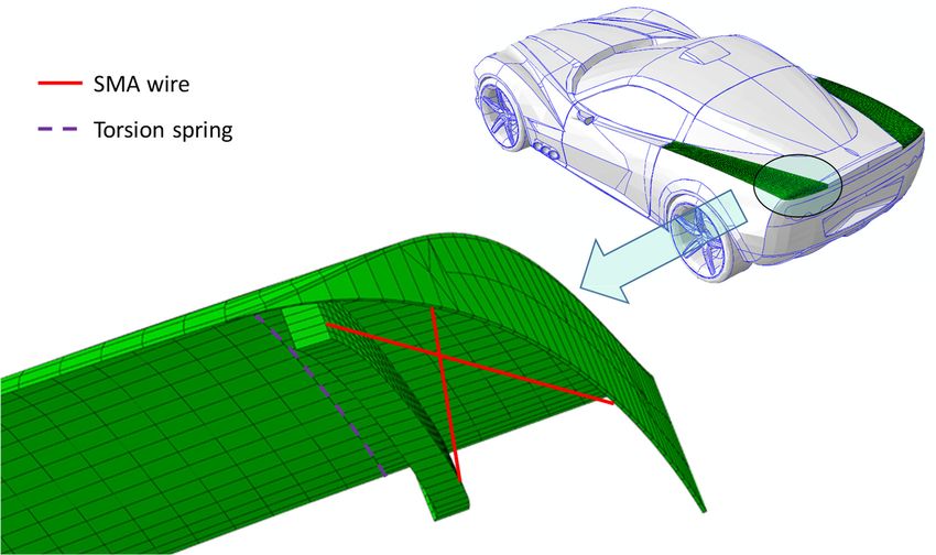
Materials 2019, 12, 708                                                                              2 of 19

actuation is finalized to modify the aerodynamic field around the vehicle, by morphing specific key
components in order to improve the car performances under varying service conditions. Numerical
implementation of the investigated case studies is provided as justification of the feasibility of the
proposed design configurations under realistic aerodynamic loads. In Section 2, the state of the
art of SMA research and applications is summarized. In Section 3, specific adaptive aerodynamics
applications found in the literature are presented. In Section 4, the analyzed case studies are introduced.
Finally, in Section 5, the finite element models are described and the results are discussed.

2. Overview of the State of the Art of SMA Actuators
      Several investigations on morphing concepts, focusing on morphing components, can be found in
the literature [46–51]. Interesting ideas are provided in [52], where the requirements in the development
of morphing surfaces are described, based on previous studies [53,54]. In [55], Smart Soft Composite
(SSC) actuators, composed of a woven smart fabric and glass-fiber fabric, were applied to a scaled rear
spoiler. The woven smart fabric, consisting of glass fibers with orthogonally placed Ni-Ti SMA wires
within a soft polymer, was combined with additional layers of glass-fiber fabric placed eccentrically
with respect to the structure neutral plane. The mechanical properties and the deformations of the
resulting SSC can be tailored by modifying the number, orientation, and stacking sequence of both
woven and glass-fiber layers. The device was actuated through Joule heating. The different sections of
the spoiler can be actuated independently to induce asymmetrical deformations. Experimental tests
in wind tunnel were performed on the SSC applied to a 1:8 scale vehicle. The drag force, downforce,
side force, and yawning moment induced by bending and bend-twist deformations were investigated.
According to the results, the structure was capable of large deformations while withstanding the
external aerodynamic load. Moreover, the structure returned to its initial state once unloaded.
      In [56], a comprehensive theoretical and experimental description of an active SMA-FRP
(Fiber-Reinforced Plastic) hybrid structure was presented. A material model, able to accurately predict
the SMA actuation behavior, was introduced. The proposed model was validated by comparing the
numerical results with experimental data resulting from the experiments. In [57], guidelines for reliable
active SMA-FRP hybrid composite were deduced, based on experimental tests.
      Other studies are focused on the modification of the wing geometry by integrating SMA wires in
the wing surface [58,59], resulting in an adaptive structure. It is worth highlighting two significant
patents. According to the first [60], the wing geometry can be modified by electrically actuating SMA
wires embedded within glass fiber skins of a sandwich structure with a honeycomb core. On the other
hand, the second patent [61] deals with SMA technologies used to control the curvature of an adaptive
wind turbine blade for variable wind conditions.
      Additional research can be found, focused on the adoption of the SMA technologies to the
development of biologically inspired structures able to mimic the behavior of living beings [62–66].
In [67], the aerodynamic performance of a UAV (Unmanned Aerial Vehicle) morphing winglet, able to
mimic the wing-tip deformation of gliding birds, was presented. A smart soft composite, constituted
of shape memory alloy wires and glass fibers embedded in a soft polymeric matrix, was used to
manufacture morphing winglets that modify their shape without any mechanical device. Preliminary
analyses were carried out to determine the flexural stress-strain relationship by means of three-point
bending tests, taking into account various SMA wire diameters and glass-fiber layers. Moreover,
the effects, in terms of winglet end-edge deflection, of adopting different SMA wire diameters,
different volume fraction of the embedded SMA, and different glass-fiber layers in the winglet were
assessed. In order to evaluate the aerodynamic coefficients, experimental tests were conducted in an
open-blowing wind tunnel, considering different angles of attack. The morphed geometry was found
to improve the L/D ratio to 5.8%.
      In [68], the development of smart components for advanced aircraft systems is presented. SMA
hybrid composite panels were considered thanks to their superior performance in terms of thermal
buckling and post-buckling behavior, fatigue, dynamic, and structural acoustic response. The aim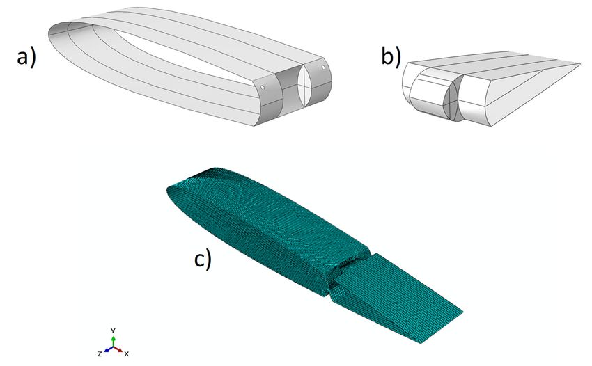
Materials 2019, 12, 708                                                                             3 of 19

is to manufacture SMA-based composite panels for the reduction of the sonic fatigue in aeronautic
structures. Moreover, in [69–73] the superior performance in terms of energy absorption and impact
response of Shape Memory Alloy Hybrid Composites (SMAHC) is assessed. Other applications of
SMA can be related to SMA wires embedded in complex wing structures [74–76], while in [77], SMA
wires interact with a supportive system of pins and springs to actuate an articulated control surface.
      Further studies focused on the analytical [78–86], numerical [59,65,66,79,81,87–93], and
experimental [54,59,65,66,78–80,90–101] investigation of SMA-based smart structures. Indeed, SMA
were used as axial [91], flexural [54,65,66,93,98–100], twisting [94,95], or non-planar [79,96] actuators.
      An experimental/numerical investigation on a device capable of multiple actuation modes
was introduced in [102]. The device was composed of four SMA wires embedded in a PDMS
(polydimethylsiloxane) soft matrix. One or two SMA wires can be activated at once. Since the
SMA wires are positioned at a negative or a positive eccentricity with respect to the middle plane of the
device, the actuation resulted in an out-of-plane displacement. Hence, activating the different SMAs
was able to induce bending mode, twisting mode, or a combination of bending and twisting modes.
Experimental tests were performed to measure the deflection and the twisting angle of the device
during the actuation of the different SMA wires. According to the experimental tests, deformations up
to 160◦ , in both the pure bending and twisting modes, were observed. Moreover, the same device was
able to deform up to 80◦ for both bending and twisting in the combined mode. Finally, finite element
simulations were presented to predict the device behavior in terms of mode, direction, and deformation
magnitude. Tanaka-based models [103] were used to numerically simulate the SMA thermomechanical
behavior. The numerical results were found to be in agreement with the experimental ones.
      Important studies on SMA modeling can be found [104,105]. In particular, in [104]
one-dimensional thermodynamics and statistical thermodynamics models for a crystalline body,
characterized by an austenitic phase and martensitic twins, were developed. In [105], an overview of
SMA actuators in smart structures was presented, focusing on their modeling and simulation.
      In [106], the mechanical properties of unsymmetrical smart composite laminates were
experimentally determined. The investigated laminates were composed of two layers: a unidirectional
carbon fiber epoxy laminate and a SMA wire epoxy laminate. The final structure was able to bend
under an applied thermal load. Four configurations were analyzed and characterized by different
spatial densities of the SMA wires, to assess their influence on the mechanical behavior of the specimens.
Conventional tensile machines were found to be unsuitable for evaluating the mechanical properties
of the laminate due to the asymmetry of the specimens. Therefore, a specially developed tensile testing
machine was used for asymmetrical materials. According to the experimental results, the mechanical
properties of the laminate are slightly enhanced by increasing the SMA wires density.
      In [107], the relationship between stress and deformation in a composite structure with embedded
SMA wires was investigated. The influence of SMA wires in a composite plate and the reliability of
the actuation of hybrid composites by means of shape memory alloys were assessed. SMA Ti-Ni wires
embedded in epoxy resin were considered. Experimental tests were conducted on the specimens by
applying a tensile external load. Moreover, the strength of the SMA-matrix interface was experimentally
determined by means of pull-out tests. The tests were performed at different temperatures: lower
than the austenite start temperature and higher than the austenite finish temperature, to completely
characterize the SMA mechanical behavior. Numerical analyses were performed to simulate the SMA
behavior by means of the superelastic shape memory material model available in LS-Dyna.
      The actuating ability and reliability of small hysteresis SMA hybrid composites were studied
in [108], where basic guidelines for the design of SMA hybrid composites were provided based on
experimental studies. In particular, the investigated hybrid laminate consisted of pre-strained TiNiCu
wires coupled with glass and Kevlar fibers epoxy prepreg. It was found that the alloy is characterized
by very small hysteresis during the thermal cycle. Moreover, the actuating potential of the considered
SMA wires is not negatively affected by the curing process, up to 413 K. The study also focused on
the effect of the SMA pre-strain. In particular, high pre-strain was found to result in high internal
Materials 2019, 12, 708                                                                              4 of 19

stress, which both weakens the SMA wires/matrix interface and reduces the actuation ability of the
laminate. The debonding can be delayed by adding fibers with negative thermal expansion coefficient,
like Kevlar ones. Finally, the working temperature of the SMA laminate was required to be lower than
the glass transition temperature of the matrix and the debonding temperature of the interface.
     Other works on the behavior of 3D adaptive structures composed of reinforced plastic fibers
based on shape memory alloys can be found in the literature [7,109–111]. In particular, experimental
investigations of hybrid yarn-based actuators with SMA cores were carried out in [112]. Several
parameters of the structure have been considered for the experimental tests, in order to determine the
spatial deformation behavior of the 3D actuator.
     However, designing with SMA can be very challenging, due to their limitations. Indeed, one
of the most cumbersome issue encountered when designing with SMA is related to their actuation
and de-actuation speeds. In [113], a large electrical current was used to improve the actuation
speed of SMA-based actuators by increasing the heating rate. Moreover, the size (diameter) of the
SMA wire plays a fundamental role in the actuation speed [114]. Indeed, lower-diameter wires are
characterized by higher external surface/volume ratios, increasing the heating and cooling speeds.
In [115], the actuation frequencies of different SMA materials were investigated. The frequency was
increased by using different active cooling systems, such as thermal gel, flowing air, heat sinking and
forced air, and fluid quenching.
     Furthermore, limitations related to the fatigue life, which affects the durability and the reliability
of SMA devices, must be addressed. In [116], the effects of the stress level, of the thermal cycling
temperature interval, and of the heat-treatment state on the fatigue-life performances of TiNi
wires were investigated. According to the study, the fatigue life is strongly influenced by the
temperature interval adopted during the thermal cycling. The fatigue life of SMA wires is also
strongly influenced by the stress and strain reached in their actuated state, as suggested in [117], where
SmartFlex NiTi wires subjected to cyclic tensile loads were experimentally investigated. To reduce
the thermal and mechanical overstresses induced in actuated SMAs, bi-stable configurations were
investigated [118–122] to develop mechanisms able to shift between a stable de-actuated configuration
and a stable actuated configuration. Hence, the activation of the SMA is needed to actuate and
de-actuate the devices, resulting in energy-free actuation states where an electric current is not needed
to keep the device in its actuated configuration, reducing the power consumption and the thermal and
mechanical overstresses as well. Moreover, in [123] considerations related to the low energy efficiency
of SMA actuators ware addressed. Different load cases for SMA actuators were compared, resulting in
an efficiency that ranges between 0.013% and 1.3%.

3. Adaptive Aerodynamic Applications
     Adaptive aerodynamics is one of the most promising fields of applications for shape memory alloy
components, thanks to their morphing capabilities. To date, several solutions have been investigated
to modify the aerodynamic field in aeronautical applications. In [124], a stretchable UAV wing able to
increase its planform area by 80% is presented. Shape Memory Polymers (SMP) were used to modify
the wing chord, to tailor the wing to specific scenarios. The adoption of actively cooled SMA for the
deployment of flexible control surfaces was investigated in [48], while in [96] SMA wires were used to
modify the camber of a morphing wing. Experimental and numerical investigations on a morphing
airfoil were carried out in [58], where SMA springs were used to actuate discrete points of the structure
to achieve the desired deformation. In [125], SMP hinges, adopted to modify the sweep angle of a
wing, were numerically and experimentally investigated, while in [126] the thickness of a flexible skin
morphing wing is controlled by means of SMA actuators. A feasibility study of wing flap actuation
based on shape memory alloys is presented in [127]. A wing composed of different telescopic segment
deployed by means of SMA actuators is presented in [29] to improve the aerodynamic performances
while reducing the wing volume stowage. In [128,129], SMAs were used to design and manufacture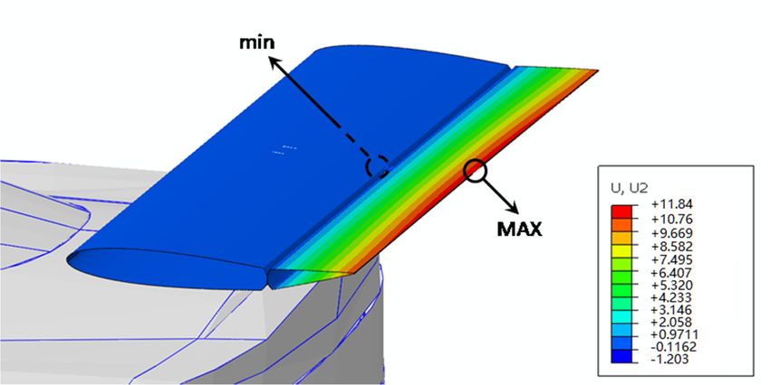
Materials 2019, 12, 708 5 of 19
Materials 2018, 11, x FOR PEER REVIEW 5 of 19
smart vortex generators, and their performance was investigated by means of experimental wind
tunnelFigure
Materials 2018,111,
tests. Insummarizes the present
x FOR PEER REVIEW
[38], an application and future
to deploy and applications of SMA
stow a flap edge concepts
fence for adaptive airplanes
is presented. 5 of 19
aerodynamics.
Figure 1 summarizes the present and future applications of SMA concepts for adaptive
Figure 1 summarizes the present and future applications of SMA concepts for adaptive airplanes
airplanes aerodynamics.
aerodynamics. Aileron/flap Control surfaces
Winglet Aileron/flap Control surfaces
Fuselage
Winglet
Fuselage
Wing
Wing Vortex generators
Vortex generators
Figure 1. Locations of adaptive aerodynamic applications in the aeronautical field.
Figure1.1.Locations
Figure Locationsof
ofadaptive
adaptive aerodynamic applicationsininthe
aerodynamic applications theaeronautical
aeronautical field.
field.
The solutions developed for adaptive aerodynamics can be easily transferred from the
The solutions
The
aeronautical solutions
to thedeveloped
automotivefor adaptive
developed for Inaerodynamics
adaptive
field. can field,
aerodynamics
the automotive be can
easily
betransferred from the aeronautical
easilyaerodynamic
adaptive transferred from the
applications
toinclude,
the automotive
aeronautical
but are field.
to not
the In the
to,automotive
automotive
limited field. In of
actuation field,
the adaptive
automotive
external aerodynamic
field,
surfaces, applications
adaptiveand/or
spoilers, aerodynamic include,asbut
applications
grill/louvers, are
shown
not include,
limitedbut
in Figure 2.to, are not
actuationlimited
of to, actuation
external of
surfaces, external surfaces,
spoilers, and/or spoilers, and/or
grill/louvers, grill/louvers,
as shown in as shown
Figure 2.
in Figure 2.
Figure 2. Locations of adaptive aerodynamic applications in the automotive field.
Figure2.
Figure 2.Locations
Locations of adaptive
adaptiveaerodynamic
aerodynamicapplications
applicationsinin
thethe
automotive field.
automotive field.
In this work, two preliminary case studies, finalized to the adaptive aerodynamic, are briefly
InInthis
introduced.
thiswork,
work, two
two preliminary
The presented
preliminary case
case studiescase studies, finalized
aimstudies, finalizedto
to demonstrate tothe
theadaptive
adaptive
feasibility
aerodynamic,
aerodynamic,
and inspire
areare
briefly
briefly
future applications
introduced.
introduced. The
The presented
presented case
case studies
studies aim
aim to
to demonstrate
demonstrate feasibility
feasibilityand inspire
and future
inspire applications
future applications
to develop SMA-based devices in the adaptive aerodynamics field. Hence, in this preliminary design
totodevelop
stage,
developSMA-based
SMA-based devices
the SMA characteristics
devices in
in the
have the adaptive aerodynamics
notadaptive
been taken aerodynamics
into account;
field. Hence,
field. Hence,
instead
in in
this
we focus
preliminary
this preliminary
on
design
design
the load exerted
stage,
stage, the
the SMA
SMA characteristics
characteristics have
have not
not been
been taken
taken into account;
into account; instead we
instead wefocus on
focus the
on load
the exerted
load exerted
during the actuation. Indeed, in an advanced design stage, more detailed analyses must be performed,
during the actuation. Indeed, in an advanced design stage, more detailed analyses must be
during the
supported byactuation.
experimental Indeed, in the
data. In an proposed
advancedcase design stage,
studies, SMA more detailed
actuators haveanalyses must to
been adopted be
performed, supported by experimental data. In the proposed case studies, SMA actuators have been
performed,
modify the to supported byfield
aerodynamic experimental
of vehicle data. In the proposed
on demand. case studies, SMA actuators have been
adopted modify the aerodynamic field of vehicle The presented
on demand. case
The studies
presented are
casefocused
studiesonarethe
adopted
spoiler to modify
andononthe the
thespoiler aerodynamic
rear upper field of vehicle on demand. The presented case studies are
focused and onpanel components.
the rear upper panel components.
focused on the spoiler and on the rear upper panel components.
4. Description of Case Studies
4. Description of Case Studies
4.1. Case Study #1—Trailing Edge Actuation
4.1. Case Study #1—Trailing Edge Actuation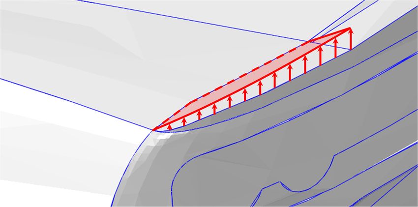
Materials 2019, 12, 708                                                                                       6 of 19

4. Description of Case Studies
    Materials 2018, 11, x FOR PEER REVIEW                                                                        6 of 19
4.1. Case Study #1—Trailing Edge Actuation
          The aim of Case study #1 is to demonstrate the feasibility of SMA-based actuation of a spoiler
      The aim of Case study #1 is to demonstrate the feasibility of SMA-based actuation of a spoiler
    trailing edge under service aerodynamic loads. A NACA 0012 airfoil has been considered as the
trailing edge under service aerodynamic loads. A NACA 0012 airfoil has been considered as the spoiler
    spoiler section, as shown in Figure 3.
section, as shown in Figure 3.

              Figure 3. Spoiler and actuated elevator: (a) cross section; (b) isometric view (unit: mm).
                 Figure 3. Spoiler and actuated elevator: (a) cross section; (b) isometric view. (unit: mm)
     The trailing edge actuation will result in a variation in drag and downforce. From preliminary
aerodynamic   studies,edge
         The trailing   a requirement   of atresult
                             actuation will   least 10
                                                     in mm  trailing in
                                                        a variation   edge
                                                                        dragdisplacement should
                                                                              and downforce.    be achieved
                                                                                             From  preliminary
to guarantee  a significant
    aerodynamic    studies, avariation of theofaerodynamic
                              requirement       at least 10 mmfield.
                                                                 trailing edge displacement should be achieved
    to guarantee a significant variation of the aerodynamic field.
4.2. Case Study #2—Rear Upper Panel Actuation
    4.2.
      TheCase
           aimStudy
                of the#2—Rear   Upper
                       second case       Panel
                                      study     Actuation
                                             (see Figure 4) is to demonstrate the feasibility of the actuation of
rear upperThepanels
               aim ofofthe
                        a vehicle,
                           secondinducing
                                     case studya variation of the
                                                  (see Figure  4) aerodynamic    field,the
                                                                  is to demonstrate     with consequent
                                                                                           feasibility     variation
                                                                                                       of the  actuation
of drag  and  downforce    to improve    the  vehicle performance     under service  aerodynamic
    of rear upper panels of a vehicle, inducing a variation of the aerodynamic field, with consequentloads. In order
to perform   realistic numerical    computations,    the geometry     configuration  of an  existing
    variation of drag and downforce to improve the vehicle performance under service aerodynamic      sports car  has
been  takenIninto
    loads.    orderaccount.   From
                      to perform     preliminary
                                   realistic        aerodynamic
                                             numerical               studies,
                                                         computations,    the ageometry
                                                                                10 mm displacement
                                                                                         configurationof  ofthe  rear
                                                                                                             an existing
upper  panel   has  been  considered    sufficient to significantly   modify  the aerodynamic     field.
    sports car has been taken into account. From preliminary aerodynamic studies, a 10 mm displacement
    of the rear upper panel has been considered sufficient to significantly modify the aerodynamic field.
Materials 2019,
Materials 12, 11,
2018, 708x FOR PEER REVIEW 7 of7 of
19 19
Materials 2018, 11, x FOR PEER REVIEW 7 of 19
Figure4.4.Rear
Figure Rear panel actuation.
panel actuation.
Figure 4. Rear panel actuation.
5. Numerical
5. NumericalSimulation
Simulation
5. Numerical Simulation
5.1. SMA Modeling
5.1. SMA Modeling
5.1. SMA Modeling
The Shape
The ShapeMemory
Memory Alloys
Alloysare
aremetallic
metallicalloys able to
alloys able torecover
recoveranan initial
initial prescribed
prescribed shapeshape
whenwhen
The Shape
subjected Memory Alloys
to temperature are metallic
variation. alloysanable to recover an initial prescribed shape when
subjected to temperature variation. InInparticular,
particular, an increase
increase ofoftemperature
temperature beyond a prescribed
beyond a prescribed
subjected
threshold togenerates
temperature variation.
a phase In particular,
transition an increase
from aa martensitic
martensitic of temperature
crystal to beyond aaustenitic
prescribed
threshold generates a phase transition from crystalstructure
structure atostable
a stable austenitic
threshold
crystallinegenerates aasphase
structure, shown transition from a the
martensitic crystalinduces
structure to a stable austenitic
crystalline structure, as shown in in Figure5.5.
Figure Since
Since the phase
phasetransition
transition a rearrangement
induces a rearrangement of theof the
crystalline structure,
microstructural as shown
arrays, the SMA in Figure 5. Since
mechanical the phase
properties transition
including induces
the elastic a rearrangement
modulus and the yieldof the
microstructural arrays, the SMA mechanical properties including the elastic modulus and the yield
microstructural arrays, themodified
strength are significantly SMA mechanical
[130–133]. properties including the elastic modulus and the yield
strength are significantly modified [130–133].
strength are significantly modified [130–133].
Austenite
Austenite
Ms Af
100
% Austenite
Ms Af
100
% Austenite
0 Mf As
deformation 0 Mf As
deformation Temperature
Martensite Martensite Temperature
Martensite Martensite
Figure 5. (Left) NiTiNOL transformation; (right) austenite variation as a function of the
temperature.
Figure 5. (Left) NiTiNOL transformation; (right) austenite variation as a function of the temperature.
Figure 5. (Left) NiTiNOL transformation; (right) austenite variation as a function of the
Among Among the other
the other SMAs,
SMAs, NiTiNOL,
NiTiNOL, antemperature.
an alloyalloy based
based on nickel
on nickel andand titanium
titanium (Nickel
(Nickel Titanium
Titanium Naval
Naval Ordnance Laboratory), is one of the most
Ordnance Laboratory), is one of the most used and investigated. used and investigated.
Among the other
In this work, SMAs,wire
a NiTiNOL NiTiNOL,
is modeledan alloy based by
in ABAQUS onmeans
nickelofand
lineartitanium
3D beam(Nickel Titanium
B31 elements.
In this work, a NiTiNOL wire is modeled in ABAQUS by means of linear 3D beam B31 elements.
In this phase, a 100 mm long wire, characterized by a 1
Naval Ordnance Laboratory), is one of the most used and investigated.mm diameter circular profile representative
In this phase, a 100 mm long wire, characterized by a 1 mm diameter circular profile representative of
of aInbundle of SMA
this work, wires, is considered.
a NiTiNOL A NiTiNOL
wire is modeled Ni52Ti48by
in ABAQUS alloy [134]
means ofhas been
linear 3Dtaken
beam into
B31account.
elements.
a bundle
Table of1 SMA
reportswires,
the is considered.
mechanical A NiTiNOL
properties of the SMA Nimaterial
52 Ti48 alloy [134] has been taken into account.
system.
In this phase, a 100 mm long wire, characterized by a 1 mm diameter circular profile representative
Table 1 reports the mechanical properties of the SMA material system.
of a bundle of SMA wires, is considered. A NiTiNOL Ni52Ti48 alloy [134] has been taken into account.
Table 1 reports the mechanical properties of the SMA material system.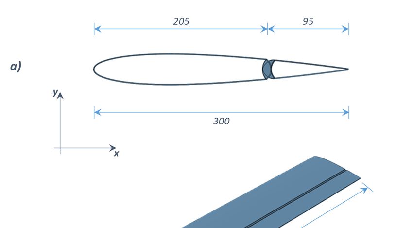
Materials 2019, 12, 708                                                                                8 of 19

                                         Table 1. Ni52 Ti48 mechanical properties [134].

                          As (◦ C)      Af (◦ C)   Ms (◦ C)    Mf (◦ C)    EA (GPa)         EM (GPa)
                           41.23         69.60       19.67       3.91          68              21

     A simplified SMA material model has been adopted. This approach, although not accounting
for all the characteristics of the SMA such as the hysteresis, can still be used in a preliminary
study to evaluate the load resulting from the SMA actuation. Indeed, the main advantage of
this approach is the simplicity of implementation in commercial codes, since it only requires
defining temperature-dependent material properties, such as elastic modulus E and Coefficient of
Thermal Expansion (CTE) α. However, in a more advanced design stage, detailed SMA constitutive
models [135–139] must be used to assess the behavior of the SMA actuators.
     According to [140,141], the variations of both the elastic modulus E and the CTE α are taken into
account as the temperature increases. In this work, the experimental data found in [134,141] have been
used. In particular, the elastic moduli and the coefficients of thermal expansion needed to describe the
behavior of the alloy were derived from a database of experimental tests, exploiting the calibration
proposed in [142]. In particular, the elastic moduli E was experimentally measured from isothermal
tensile tests: for each desired temperature, the SMA wires were subjected to a tensile load at a constant
temperature. Moreover, the CTEs α were experimentally evaluated by applying an increasing thermal
load on a pre-strained SMA wire (4% in the current study). Hence, the CTE at different temperatures
can be expressed as a function of the measured strains and temperatures.
     In order to numerically replicate the SMA characterization procedure, as a preliminary step to
the case studies analyses, a NiTiNOL wire has been clamped at its extremities. An initial temperature
equal to 25 ◦ C has been assumed, while the elastic modulus and the thermal expansion coefficients
adopted have been changed with temperature according to Table 2.

                      Table 2. SMA temperature-dependent mechanical and thermal properties.

                                     Temperature (◦ C)        E (MPa)          α (◦ C−1 )
                                            24                21,259         6.61 × 10⁻⁶
                                            30                19,905         6.61 × 10⁻⁶
                                            35                21,303        −1.8777 × 10⁻⁴
                                            40                21,483        −5.1203 × 10⁻⁴
                                            55                38,346        −3.8596 × 10⁻⁴
                                            60                43,625        −3.0564 × 10⁻⁴
                                            70                55,325        −1.9657 × 10⁻⁴
                                            80                57,519        −1.5404 × 10⁻⁴
                                            90                55,440        −1.3077 × 10⁻⁴
                                            110               58,790        −9.0464 × 10⁻⁵
                                            150               57,750        −5.9532 × 10⁻⁵

     This analysis is aimed at the validation of the proposed simplified material model with respect
to the literature data. Indeed, it does not describe the behavior of the SMA wire used as an actuator,
due to the different boundary conditions. The results of the ABAQUS numerical test, in terms of
stress as a function of the temperature, have been found to be in agreement with the data reported
in [140], as shown in Figure 6, where the numerical test results are compared to the reference ones.
Thus, the validated material model has been used in the following test cases, tailoring the number of
SMA wires according to the specific application.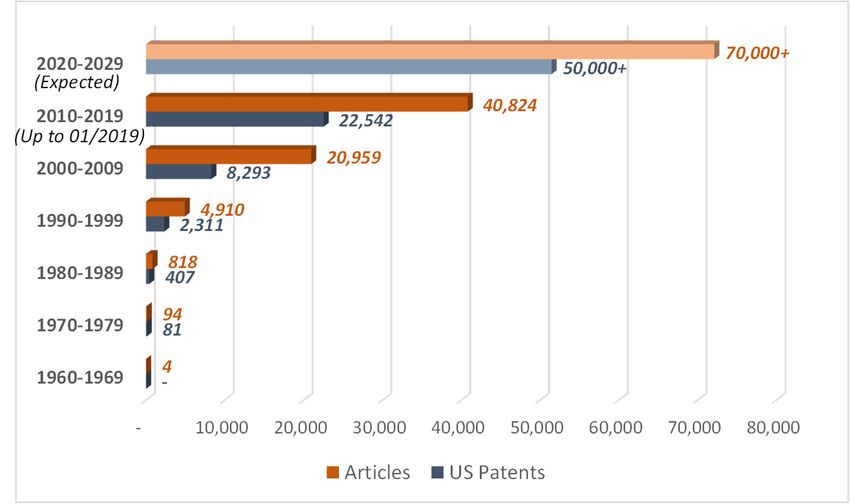
Materials 2019, 12, 708 9 of 19
Materials 2018, 11, x FOR PEER REVIEW 9 of 19
Materials 2018, 11, x550.00
FOR PEER REVIEW 9 of 19
450.00
550.00
σ [MPa] 350.00
450.00
350.00
250.00
Reference [140]
σ [MPa]
250.00 ABAQUS
150.00 Reference [140]
ABAQUS
150.00
50.00
50.00
-50.00
25.00
-50.00 45.00 65.00 85.00 105.00
25.00 45.00 65.00
Temperature [°C] 85.00 105.00
Temperature [°C]
Figure 6. Numerical test results [140].
Figure 6. Numerical test results [140].
Figure 6. Numerical test results [140].
5.2. Case Study #1
5.2. Case Study
5.2. Case #1 #1
Study
In Case study #1, NiTiNOL wires have been integrated into an aluminum spoiler structure.
In Case
According In to study
Case
thestudy #1,#1,
proposedNiTiNOL
NiTiNOL wires
wires have
finite element have been integrated
been integrated
discretization, twointointo
solid an aluminum
anmodels
aluminum spoiler
spoiler
(Figure structure.
structure.
7a,b) have been
considered. The first model represents the fixed part of the spoiler, while the second representsbeen
According
Accordingto the
to proposed
the proposed finite
finiteelement
element discretization,
discretization, two
two solid
solid models
models (Figure
(Figure 7a,b) 7a,b)
have have
been the
considered.
considered.
moving TheThe
tip (see first
first
Figure model
model
7). The represents
represents
two solidthethe fixed have
fixed
models part
partofofthe
thespoiler,
been spoiler,while
discretized themeans
while
by second
the ofrepresents
second four-nodedthe shell
represents the
moving
moving tip tip (see Figure
(seeaFigure 7). The two
7). integration
The two solid solid models
models have
haveInbeen
been discretized
discretizedby means
by of
meansof four-noded shell
elements with reduced scheme (S4R). Figure 7, details both of four-noded
solid shell
models with
elements
elements with with
a a reduced
reduced integrationscheme
integration scheme (S4R).
(S4R). In
InFigure
Figure 7, 7,
details of both
details of solidsolid
both models with with
models
corresponding numerical discretization are shown, while the mechanical properties of the adopted
corresponding numerical discretization are shown, while the mechanical properties of the adopted
corresponding
aluminum alloy numerical
have been discretization
reported are shown, while the mechanical properties of the adopted
aluminum alloy have been reportedininTable
Table3.3.
aluminum alloy have been reported in Table 3.
Figure 7. 7.Case
Figure Casestudy
study #1
#1 (details): (a,b)geometries;
(details): (a,b) geometries;(c) (c)
FEM.FEM.
Table 3. Al2024-T6 mechanical properties.
Table 3. Al2024-T6 mechanical properties.
Figure 7. Case studyE #1 (details): (a,b)
(MPa) ν (-)geometries; (c) FEM.
E (MPa) ν (-)
72,300
72,300 0.33
0.33
Table 3. Al2024-T6 mechanical properties.
E (MPa)
A hinge placed between the fixed and the moving partν allows
(-) the rotation of the tip. As already
72,300 0.33
mentioned, two 120-mm-long SMA wires have been introduced to connect the fixed part to the moving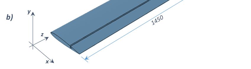
Materials 2018, 11, x FOR PEER REVIEW 10 of 19
A hinge placed between the fixed and the moving part allows the rotation of the tip. As already
mentioned, two 120-mm-long SMA wires have been introduced to connect the fixed part to10the
Materials 2019, 12, 708 of 19
moving tip, through two holes drilled on the fixed part (see Figure 7a). The position of the SMA wires
has been chosen to maximize the moment with respect to the hinge. The section of the wires and the
tip, properties
through two holes
of the drilledare
material ondefined
the fixedin part (see Figure
agreement 7a).preliminary
with the The position of the
study onSMA
SMAwires has been
materials. In
order
chosen to to guarantee
maximize thethe return with
moment of therespect
devicetotothe
its hinge.
initial The
position at SMA
section of thedeactivation,
wires and thetwo elastic
properties
beams
of the have been
material placed between
are defined the fixed
in agreement and
with moving
the tip opposed
preliminary studytoon
theSMA
SMAmaterials.
wires. Details of theto
In order
SMAs and
guarantee the beams
returnlocations are reported
of the device in Figure
to its initial 8. at SMA deactivation, two elastic beams have
position
been placed between the fixed and moving tip opposed to the SMA wires. Details of the SMAs and
beams locations are reported in Figure 8.
Figure 8. Trailing edge actuation, details of the SMA, hinge, and beam locations.
Figure 8. Trailing edge actuation, details of the SMA, hinge, and beam locations.
An initial 25 ◦ C temperature has been defined for the whole model. The SMA wires have been
actuatedAn byinitial
increasing their temperature
25 °C temperature has been 150 ◦ C.for
to defined Two thedifferent analyses
whole model. have wires
The SMA been considered.
have been
Theactuated
first analysis has been finalized to the testing of the SMA wire mechanical behavior
by increasing their temperature to 150 °C. Two different analyses have been considered. and the The
latter
has first
beenanalysis
finalized to the investigation of the influence of the external aerodynamic load
has been finalized to the testing of the SMA wire mechanical behavior and the latter has and the elastic
loadbeen
of the beams to
finalized onthetheinvestigation
SMA mechanical of thebehavior
influenceand on external
of the the SMAaerodynamic
actuation. Indeed,
load and anthe
equivalent
elastic
aerodynamic load of 2.95 kg, evaluated by means of preliminary aerodynamic
load of the beams on the SMA mechanical behavior and on the SMA actuation. Indeed, an equivalent simulations, has been
applied on the moving
aerodynamic load oftip.2.95Since the weightbyismeans
kg, evaluated one order of magnitude
of preliminary lower thansimulations,
aerodynamic the aerodynamic load,
has been
it has been neglected.
applied on the moving In Table 4, thethe
tip. Since results
weight of both
is oneconfigurations are reported,
order of magnitude while
lower than theFigure 9 shows
aerodynamic
Caseload, it has
study #1 been neglected.
in actuation In Table
mode with4,thetheapplication
results of both configurations
of both are reported,
the aerodynamic loadwhile Figure
and the 9
elastic
shows Case study #1 in actuation mode with the application of both the aerodynamic
load from the beams. The maximum values of stress and strain observed during the actuation in the load and the
SMA elastic
wires load
arefrom the beams.
250 MPa 4 µε,
and 10The maximum values
respectively. of stress and
According strain
to the observed
numerical during
results, the
the actuation
investigated
in the SMA wires are 250 MPa and 10
device can satisfy the displacement requirement (10 mm).4 με, respectively. According to the numerical results, the
investigated device can satisfy the displacement requirement (10 mm).
Table 4. Results of Case study #1.
Table 4. Results of Case study #1.
Boundary Conditions Max Displacement (mm)
Boundary Conditions
Materials 2018, 11, x FOR PEER REVIEWload
Max Displacement (mm) 11 of 19
Without and beam 16.03
Without load
With load and
and beam
beam 16.03
11.84
With load and beam 11.84
Figure
Figure 9. Case
9. Case study
study #1:actuated
#1: actuated structure
structure. (unit:
(unit:mm).
mm).
5.3. Case Study #2
Case study #2 is focused on the actuation of the rear upper panel of a bonnet, by means of
properly located 270-mm-long NiTiNOL wires, aimed to increase the drag and the downforce. The
numerical model has been realized by means of eight-noded 3D solid elements with a reducedMaterials 2019, 12, 708 11 of 19
5.3. Case Study #2
Case study #2 is focused onFigure the actuation of the rear upper panel of a bonnet, by means of properly
9. Case study #1: actuated structure. (unit: mm).
located 270-mm-long NiTiNOL wires, aimed to increase the drag and the downforce. The numerical
model has 5.3.
beenCase Study #2by means of eight-noded 3D solid elements with a reduced integration scheme
realized
(C3D8R). A hinge has been
Case study #2 is placed
focused onbetween the fixed
the actuation of the part of the
rear upper bonnet
panel and the
of a bonnet, by rear
meansupper
of panel
properly
interfaces to allowlocated 270-mm-long
its rotation. TheNiTiNOL
rear upper wires,panel
aimed can
to increase
recoverthe drag and theposition
its initial downforce. byThe
means of a
numerical model has been realized by means of eight-noded 3D solid elements with a reduced
torsion spring placed in the hinge. A 1.2 kg equivalent aerodynamic load, evaluated by means of
integration scheme (C3D8R). A hinge has been placed between the fixed part of the bonnet and the
preliminaryrear
aerodynamic simulations,
upper panel interfaces to allow has been considered
its rotation. The rear upperon the
panelmoving surface.
can recover Asposition
its initial in the previous
case study,by
the weight
means has been
of a torsion neglected
spring placed in since it isAone
the hinge. order
1.2 kg of magnitude
equivalent aerodynamicbelow the aerodynamic
load, evaluated
by means
load. An initial of preliminary
temperature equal to 25 ◦ Csimulations,
aerodynamic has been considered
has been defined on the wholeon themodel,
movingandsurface.
theAsSMA wires
in the previous case study, the weight has been neglected since ◦it is one order of magnitude below
have been the
actuated by increasing their temperature up to 150 C. In Figure 10, the
aerodynamic load. An initial temperature equal to 25 °C has been defined on the whole model,
numerical model,
including the
and location of the
the SMA wires SMA
have beenwires
actuatedandbyofincreasing
the torsion
their spring, is reported.
temperature up to 150 °C. In Figure 10,
the numerical model, including the location of the SMA wires and of the torsion spring, is reported.
Figure 10. Figure
Rear 10. Rear upper panel actuation, details of the numerical model, and locations of SMA and
upper panel actuation, details of the numerical model, and locations of SMA and
torsion spring.
torsion spring.
Finally,Materials
in Figure2018, 11,11, the
x FOR structure
PEER REVIEW in actuation mode is reported. Again, for this 12configuration,of 19
the requirement on displacements (10 mm) needed to obtain a significant aerodynamic field variation
Finally, in Figure 11, the structure in actuation mode is reported. Again, for this configuration,
has been satisfied. The maximum values of stress and strain observed during the actuation in the
the requirement on displacements (10 mm) needed to obtain a significant aerodynamic field variation
SMA wires hasarebeen
350 MPa andThe
satisfied. 400 µε, respectively.
maximum However,
values of stress it isobserved
and strain worth during
notingthethat modifications
actuation in the to the
number and SMAthewires
length are of
350the
MPaSMA wire
and 400 με,can help to However,
respectively. tailor actuation
it is worthdisplacements.
noting that modifications to
the number and the length of the SMA wire can help to tailor actuation displacements.
11. Case
Figure Figure study
11. Case #2:#2:
study actuated structure.
actuated structure. (unit:
(unit: mm).mm).
6. Conclusions and Discussion of Future Trends
An overview of SMA-based smart structures has been presented in this work. Extensive studies,
analytical, numerical, and experimental, have been found in the literature dealing with shape
memory alloys, which can be considered suitable for adaptive aerodynamic applications, thanks to
their morphing capabilities. Indeed, the research efforts on SMA-based actuators have been focused
on the development of devices able to induce axial, bending, or twisting deformations. Moreover, theMaterials 2019, 12, 708 12 of 19
6. Conclusions and Discussion
Figureof
11.Future Trends
Case study #2: actuated structure. (unit: mm).
An
6. overview of
Conclusions andSMA-based
Discussionsmart
of Futurestructures
Trends has been presented in this work. Extensive studies,
analytical, numerical, and experimental, have been found in the literature dealing with shape memory
An overview of SMA-based smart structures has been presented in this work. Extensive studies,
alloys, which can be considered suitable for adaptive aerodynamic applications, thanks to their
analytical, numerical, and experimental, have been found in the literature dealing with shape
morphing capabilities. Indeed, the research efforts on SMA-based actuators have been focused on the
memory alloys, which can be considered suitable for adaptive aerodynamic applications, thanks to
development of devices
their morphing able to Indeed,
capabilities. induce axial, bending,
the research or twisting
efforts deformations.
on SMA-based actuatorsMoreover, the adoption
have been focused
of shape memory
on the alloysofresults
development devicesinable
simpler andaxial,
to induce lighter devices
bending, or compared to the conventional
twisting deformations. Moreover,actuators,
the
significantly
adoptionreducing the weight
of shape memory and
alloys the in
results cost of theand
simpler components. Thus,
lighter devices the interest
compared to the in shape memory
conventional
alloyactuators, significantly
applications reducing
is increasing eventhe weight
more, as and the cost of by
demonstrated the the
components.
number ofThus, the interest
articles published in and
shape memory alloy applications
patents issued, as reported in Figure 12.is increasing even more, as demonstrated by the number of articles
published and patents issued, as reported in Figure 12.
Figure 12. Articles
Figure published
12. Articles and
published andU.S.
U.S.patents
patents issued. Sources:Scopus
issued. Sources: Scopus
andand Uspto.
Uspto. Keywords:
Keywords: “Shape
“Shape
Memory Alloy”
Memory OROR
Alloy” “Nitinol”.
“Nitinol”.Retrieved:
Retrieved: 22/01/2019.
22/01/2019.
Materials 2018, 11, x FOR PEER REVIEW 13 of 19
As a matter of fact, the majority of the applications presented in the literature are confined to
the aerospace field, where
As a matter performance
of fact, the majority of requirements
the applicationsare demanding,
presented as shownare
in the literature inconfined
detail intoFigure
the 13,
aerospace field, where performance requirements are demanding, as shown in detail in
where the number of articles clearly belonging to the aeronautical or automotive fields are compared.Figure 13,
where the number of articles clearly belonging to the aeronautical or automotive fields are compared.
Figure 13. Articles
Figure published
13. Articles ininthe
published theaeronautical andautomotive
aeronautical and automotive fields.
fields. Sources:
Sources: Scopus.
Scopus. Aeronautical
Aeronautical
keywords: (“Shape
keywords: Memory
(“Shape Alloy”
Memory OR “Nitinol”)
Alloy” AND
OR “Nitinol”) (“Aerospace”
AND (“Aerospace” OR OR
“Aeronautical”
“Aeronautical”OROR
“Flight”
OR “Aircraft”);
“Flight” ORAutomotive
“Aircraft”); keywords:
Automotive (“Shape
keywords: Memory
(“ShapeAlloy”
Memory OR Alloy”
“Nitinol”)
OR AND (“Automotive”
“Nitinol”) AND
(“Automotive”
OR “Car” OR “Car”
OR “Vehicle”). OR “Vehicle”).
Retrieved: Retrieved: 22/01/2019.
22/01/2019.
Hence, based on this literature research, a feasibility study of the development of SMA-based
smart actuators for automotive applications, mostly derived from the aerospace experience, has been
presented in this paper. In order to focus on the feasibility rather than on the executive design of SMA
concepts, in this work a simplified model, descriptive of the NiTiNOL characteristics, has been
employed. Moreover, with the same objective in mind, preliminary, if realistic, aerodynamics loads
have been considered for the proposed SMA concepts. Two case studies have been presented: theMaterials 2019, 12, 708 13 of 19
Hence, based on this literature research, a feasibility study of the development of SMA-based
smart actuators for automotive applications, mostly derived from the aerospace experience, has been
presented in this paper. In order to focus on the feasibility rather than on the executive design of
SMA concepts, in this work a simplified model, descriptive of the NiTiNOL characteristics, has been
employed. Moreover, with the same objective in mind, preliminary, if realistic, aerodynamics loads
have been considered for the proposed SMA concepts. Two case studies have been presented: the
trailing edge actuation of a spoiler (very close to the aerospace background) and the rear upper
panel deformation of a vehicle. The provided numerical analyses have demonstrated the feasibility
of the presented SMA-based smart devices. As a general remark, the key design parameters to be
considered in SMA applications, such as the maximum attained force and displacement and the
operating range temperature, can be controlled by varying the material, size, and shape of the adopted
SMA wires. Hence, the presented solutions can be improved by tailoring the SMA geometry and
material characteristics.
Funding: This research received no external funding.
Conflicts of Interest: The authors declare no conflict of interest.
References
1. Qiu, J.; Wang, C.; Huang, C.; Ji, H.; Xu, Z. Smart skin and actuators for morphing structures. Procedia IUTAM
2013, 10, 427–441. [CrossRef]
2. Weisshaar, T.A.; Duke, D.K. Induced drag reduction using aeroelastic tailoring with adaptive control surfaces.
J. Aircr. 2006, 43, 157–164. [CrossRef]
3. Bowman, J.; Sanders, B.; Cannon, B.; Kudva, J.; Joshi, S.; Weisshaar, T. Development of next
generation morphing aircraft structures. In Collection of Technical Papers, Proceedings of the 48th
AIAA/ASME/ASCE/AHS/ASC Structures, Structural Dynamics, and Materials Conference, Honolulu, HI,
USA, 22–26 April 2007; Volume 1, pp. 349–358.
4. Hwang, S.-H.; Park, H.W.; Park, Y.-B. Piezoresistive behavior and multi-directional strain sensing ability of
carbon nanotube-graphene nanoplatelet hybrid sheets. Smart Mater. Struct. 2013, 22, 015013. [CrossRef]
5. John, A.; Chen, Y.; Kim, J. Synthesis and characterization of cellulose acetateecalcium carbonate hybrid
nanocomposite. Compos. Part B Eng. 2012, 43, 522–525. [CrossRef]
6. Hou, Y.; Neville, R.; Scarpa, F.; Remilat, C.; Gu, B.; Ruzzene, M. Graded conventionalauxetic Kirigami
sandwich structures: Flatwise compression and edgewise loading. Compos. Part B Eng. 2014, 59, 33–42.
[CrossRef]
7. Wang, W.; Rodrigue, H.; Ahn, S.-H. Smart soft composite actuator with shape retention capability using
embedded fusible alloy structures. Compos. Part B Eng. 2015, 78, 507–514. [CrossRef]
8. Brinson, L. One-dimensional constitutive behavior of shape memory alloys: Thermomechanical derivation
with non-constant material functions and redefined martensite internal variable. J. Intell. Mater. Syst. Struct.
1993, 4, 229–242. [CrossRef]
9. Khoo, Z.X.; An, J.; Chua, C.K.; Shen, Y.F.; Kuo, C.N.; Liu, Y. Effect of heat treatment on repetitively scanned
SLM NiTi shape memory alloy. Materials 2019, 12, 77. [CrossRef] [PubMed]
10. Van Humbeeck, J. Shape memory alloys: A material and a technology. Adv. Eng. Mater. 2001, 3, 837–850.
[CrossRef]
11. Icardi, U.; Ferrero, L. Preliminary study of an adaptive wing with shape memory alloy torsion actuators.
Mater. Des. 2009, 30, 4200–4210. [CrossRef]
12. Coutu, D.; Brailovski, V.; Terriault, P.; Mamou, M.; Mébarki, Y.; Laurendeau, É. Lift-to-drag ratio and laminar
flow control of a morphing laminar wing in a wind tunnel. Smart Mater. Struct. 2011, 20, 035019. [CrossRef]
13. Berton, B. Shape memory alloys application: Trailing edge shape control. In Multifunctional
Structures/Integration of Sensors and Antennas, Proceedings of the RTO-MP-AVT-141, Neuilly-sur-Seine,
France, 2–4 October 2006.
14. Manzo, J.; Garcia, E. Demonstration of an in situ morphing hyperelliptical cambered span wing mechanism.
Smart Mater. Struct. 2010, 19, 025012. [CrossRef]Materials 2019, 12, 708 14 of 19
15. Dano, M.L.; Hyer, M.W. SMA-induced snap-through of unsymmetric fiber-reinforced composite laminates.
Int. J. Solids Struct. 2003, 40, 5949–5972. [CrossRef]
16. Pons, J.L. Emerging Actuator Technologies—A Micromechatronic Approach; John Wiley & Sons: London, UK, 2005.
17. Wu, R.; Han, M.-W.; Lee, G.-Y.; Ahn, S.-H. Woven type smart soft composite beam with in-plane shape
retention. Smart Mater. Struct. 2013, 22, 125007. [CrossRef]
18. Hartl, D.J.; Lagoudas, D.C. Aerospace applications of shape memory alloys. Proc. Inst. Mech. Eng. Part G J.
Aerosp. Eng. 2007, 221, 535–552. [CrossRef]
19. Fujita, H.; Toshiyoshi, H. Micro actuators and their applications. Microelectron. J. 1998, 29, 637–640. [CrossRef]
20. Koh, J.-S. Design of shape memory alloy coil spring actuator for improving performance in cyclic actuation.
Materials 2018, 11, 2324. [CrossRef] [PubMed]
21. Manfredi, L.; Cuschieri, A. Design of a 2 DOFs mini hollow joint actuated with SMA wires. Materials 2018,
11, 2014. [CrossRef] [PubMed]
22. Bellini, A.; Colli, M.; Dragoni, E. Mechatronic design of a shape memory alloy actuator for automotive
tumble flaps: A case study. IEEE Trans. Ind. Electron. 2009, 56, 2644–2656. [CrossRef]
23. Strittmatter, J.; Gümpel, P.; Zhigang, H. Long-time stability of shape memory actuators for pedestrian safety
system. J. Achiev. Mater. Manuf. Eng. 2009, 34, 23–30.
24. Williams, E.A.; Shaw, G.; Elahinia, M. Control of an automotive shape memory alloy mirror actuator.
Mechatronics 2010, 20, 527–534. [CrossRef]
25. Zychowicz, R. Exterior View Mirror for a Motor Vehicle. U.S. Patent 5166832; Britax (GECO) SA,
24 November 1992.
26. Leary, M.; Huang, S.; Ataalla, T.; Baxter, A.; Subic, A. Design of shape memory alloy actuators for direct
power by an automotive battery. Mater. Des. 2013, 43, 460–466. [CrossRef]
27. Suzuki, M. Rotatable Door Mirror for a Motor Vehicle. U.S. Patents 4626085, 2 December 1986.
28. Brugger, D.; Kohl, M.; Hollenbach, U.; Kapp, A.; Stiller, C. Ferromagnetic shape memory microscanner
system for automotive applications. Int. J. Appl. Electromagnet. Mech. 2006, 23, 107–112. [CrossRef]
29. Knowles, G.; Bird, R.W. Telescopic wing system. In U.S. Patent 6834835B1; QorTek Inc.: Williamsport, PA,
USA, 2004.
30. Manzo, J.; Garcia, E.; Wickenheiser, A.; Horner, G.C. Design of a shape-memory alloy actuated macro-scale
morphing aircraft mechanism. In Proc. SPIE 5764, Smart Structures and Materials 2005: Smart Structures and
Integrated Systems; SPIE: Bellingham, WA, USA, 2005. [CrossRef]
31. Kutlucinar, I. Aircraft with shape memory alloys for retractable landing gear. In U.S. Patent 6938416B1;
Emergency Warning Systems Inc.: Balwyn, Australia, 2005.
32. Song, G.; Ma, N. Shape memory alloy actuated adaptive exhaust nozzle for jet engine. In U.S. Patents
8245516; University of Houston: Houston, TX, USA, 2012.
33. Core, R.A. Dilating fan duct nozzle. In U.S. Patent 7716932B2; Spirit AeroSystems Inc.: Wichita, KS, USA, 2010.
34. Shmilovich, A.; Yadlin, Y.; Smith, D.M.; Clark, R.W. Integrated engine exhaust systems and methods for drag
and thermal stress reduction. In U.S. Patent 7669785B2; The Boeing Co.: Chicago, IL, USA, 2010.
35. Mons, C.M. Actuating device, bypass air bleed system equipped therewith, and turbojet engine comprising
these. In U.S. Patents 2009/0056307A1; SNECMA: Courcouronnes, France, 2008.
36. Wood, J.H. Shape changing structure in a jet engine nacelle nozzle and corresponding jet engine and
operating method. In EP Patent 1,817,489; The Boeing Co.: Chicago, IL, USA, 2007.
37. Wood, J.H.; Dunne, J.P. Morphing structure. In U.S. Patent 7340883B2; The Boeing Co.: Chicago, IL, USA, 2008.
38. Larssen, J.V.; Calkins, F.T. Deployable Flap Edge Fence. In U.S. Patent 2013/US8469315B2; The Boeing Co.:
Chicago, IL, USA, 2010.
39. Mabe, J.H.; Calkins, F.T.; Bushnell, G.S.; Bieniawski, S.R. Aircraft systems with shape memory alloy (SMA)
actuators, and associated methods. In U.S. Patent 7878459B2; The Boeing Co.: Chicago, IL, USA, 2011.
40. Widdle, R.D.; Grimshaw, M.T.; Crosson-Elturan, K.S.; Mabe, J.H.; Calkins, F.T.; Gravatt, L.M.; Shome, M.
High stiffness shape memory alloy actuated aerostructure. In U.S. Patent 2011/0030380A1; The Boeing Co.:
Chicago, IL, USA, 2009.
41. Mani, R.; Lagoudas, D.C.; Rediniotis, O.K. MEMS-based active skin for turbulent drag reduction.
Smart Struct. Mater. 2003, 5056, 9–20.
42. Mohammad, T.; Jeng-Jong, R.; Chuh, M. Thermal post-buckling and aeroelastic behaviour of shape memory
alloy reinforced plates. Smart Mater. Struct. 2002, 11, 297.You can also read