P234 User Manual - Max Machinery
←
→
Page content transcription
If your browser does not render page correctly, please read the page content below

P234 User Manual
Safety and Precautions

        Never run the meter dry or blow compressed air through the meter.
  !     Damage will occur.

        Never steam clean the meter. Damage will occur.
  !     (Bypass or remove the meter if necessary).

        Do not disassemble the meter. Damage may occur.
  !     No serviceable parts inside.

        Do not over pressurize the meter. Damage may occur.
  !     Maximum pressure is 3000 psi.

        Do not operate P234 flow meters in a hazardous environment. For flow meters
  !     rated for ATEX, UL, or cUL Class 1, Div. 1 use in a hazardous environment,
        contact Max Machinery Sales at 707.433.2662 or www.maxmachinery.com.

  i     Read the entire manual before installing and operating the meter.

  i     Verify the fluid to be measured is compatible with the flow meter.

        Filter your fluid to prevent damage from debris and foreign materials.
        10 micron filtration recommended.

        Install bypass plumbing around the flowmeter to allow for easier servicing and
        line purging/flushing without damaging the meter.

        Follow all local regulations and your company safety procedures when
        installing, operating, servicing, and maintaining your flow meter.

P234 User Manual Rev2020A - © 2008 - 2020		   i                              P234-USEMAN-REV2018A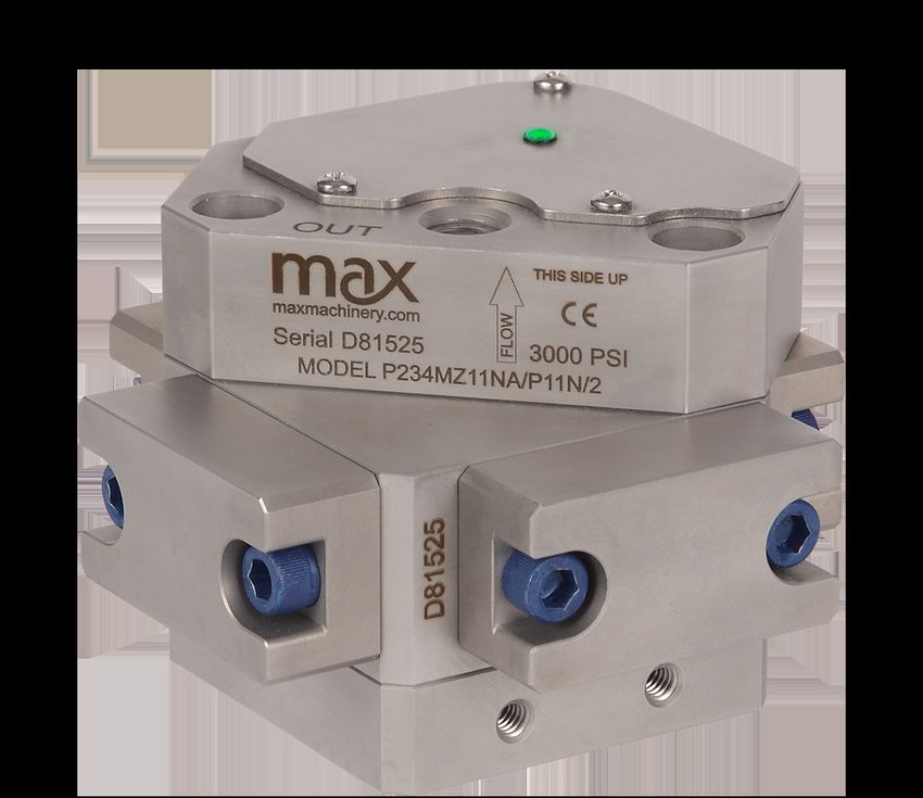
Table of Contents
Safety and Precautions......................................................................... i
Table of Contents................................................................................... ii
How It Works............................................................................................ 1
Installation................................................................................................ 1
Mechanical................................................................................................ 1
Operation................................................................................................. 2
Electrical.................................................................................................. 3
Field Compensation of Transmitter................................................... 5
LED Functions......................................................................................... 7
Specifications..........................................................................................8
Dimensions.............................................................................................10
Charts......................................................................................................10
Part Matrix...............................................................................................11
Available Accessories...........................................................................13
Troubleshooting and Service Request.............................................14
Additional Information Available.......................................................14

Max Machinery, Inc. (MMI) reserves the right to change product specifications without notice to improve performance,
reliability, or manufacturability. MMI shall not be held liable for operational, technical, or editorial errors/omissions. Visit
our web site for the latest version of this user manual.

                          Max Machinery, Inc., 33A Healdsburg Avenue, Healdsburg, CA 95448 USA
                                            707.433.2662 | www.maxmachinery.com

P234 User Manual Rev2020A - © 2008 - 2020		                      ii                                              P234-USEMAN-REV2018A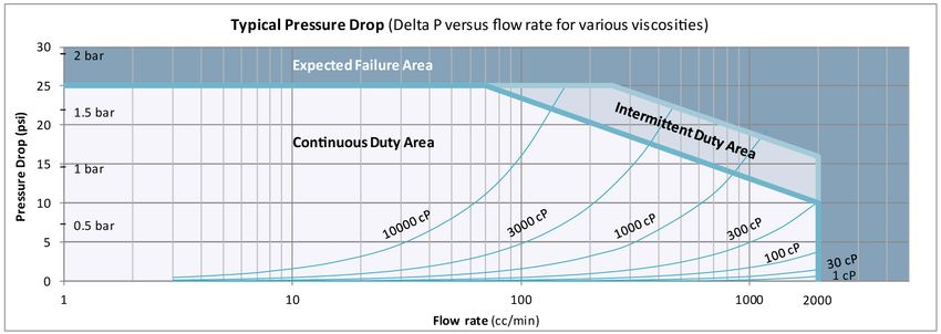
How It Works
Max P234 Precision Flow Meters are positive displacement piston meters that are able to operate over a wide range
of flow rates and fluid viscosities and are specifically designed to be compatible with aqueous based solutions. High
accuracy measurement is achieved through precision machined radial pistons that move proportional to the flow. High
resolution outputs are produced by measuring the direction and speed of the pistons and converting the signals to
analog and frequency outputs. Flows can be monitored from 1 cc/min up to 2000 cc/min with fluid temperatures from
5 deg C to 90 deg C and a maximum pressure of 3000 psi (210 bar). The meter electronics are protected against water,
dust, and most corrosive liquids. The 5-pin Turck connector provided is IP68 and mounts to the meter body via a PG-9
connection that can be adapted to conduit. Optional seal materials may be specified to allow for fluid compatibility.

The P234MEKP-### is a variant meant for use with methyl ethyl ketone peroxide (MEKP) and similar chemicals.
Different wetted materials are used to achieve compatability. The flow range is from 1 cc/min up to 500 cc/min. Contact
Max Machinery to determine if it is suitable for use in your application.

Max Machinery, Inc. designs, manufactures, calibrates, and refurbishes high accuracy, high resolution, precision liquid
flow meters under an ISO 9001:2015 certified quality management system. All Max Precision Flow Meters are tested
and calibrated in our lab and provide measurements traceable to NIST. If your calibration certificate is lost or missing,
contact MMI with your meter serial number for a copy.

Installation
Orientation: The P234 mounts vertically with the inlet port on the bottom and the outlet port on the top (See diagram on
page 2). This is the only manufacturer’s suggested mounting that will allow for air to be purged from the system. Air in
the system can cause response delays and errors in measurement.

Bypass Valves: Install valves to allow system start-up, filter replacement, or flow meter removal without completely
shutting the system down and draining the lines. See diagram.
Failure to use a bypass at start up may lead to flow meter damage due to debris, overspeeding the meter with air in the
lines, and pressure shock due to initial line surges.

Filtration: A 10 micron filter is recommended on the inlet side of the meter. If measuring bi-directional flow, a filter should
be installed on both sides of the flow meter. Materials with fibrous or non-abrasive particulate matter may need to be run
without filters.

Clean Plumbing: Before installing the flow meter, the system lines should be cleaned and free of all debris or
manufacturing particulates. Purging lines with compressed air or steam are typical cleaning methods. Do not use
compressed air or steam on the Max flow meter, damage will occur.

Mechanical
Inlet and Outlet ports may be NPT or BSPP (G-Type). The product part number defines the type of liquid fitting. Use the
part matrix located on page 10 to determine the type of ports on your product and the Specifications section on page 8
to determine the diameter and thread pitch.

The P234 may require additional mounting support beyond the fluid connection lines. Additional mounting holes
are located on two opposing sides of the base of the product. These holes are 1/4-20 UNC located 1.125 inches apart
horizontally.

P234 User Manual Rev2020A - © 2008 - 2020		                   1                                            P234-USEMAN-REV2018A
Operation
Determine that the following parameters of your flow metering system are within the specifications for the specific
meter being used:

                   Maximum System Pressure (Specifications)
                   Differential Pressure across meter (Pressure Drop Curves)
                   Maximum Flow Rate (Pressure Drop Curves)
                   Metered Fluid Temperature (Sales specification, transmitter specifications)

If the difference in metered fluid temperature versus ambient is greater than 75°F (41.6°C), see the “High
Temperature Start Up” section below.

With valves (#1) and (#2) closed, slowly open valve (#3) (bypass) to clear the lines of foreign particles and air.
Slowly open the inlet valve (#1). Slowly open the outlet valve (#2). Completely close the bypass valve (#3).

No routine maintenance, cleaning, or lubrication of the flow meter is required. A routine filter cleaning schedule
should be established. The system should be shut down if abnormal noises occur or if unusual differential pressures
across the meter are encountered.

High Temperature Start Up: For fluids above 145°F (62.8°C) based
on 70°F (21°C) ambient, a specific procedure is required. To avoid
temperature shock, flow should be very slowly ramped up over
approximately 5 min per 75°F (41.6°C) over ambient. Start with
all valves closed and smoothly open valve #3 to allow bypass flow
around the meter. Then over the calculated time interval for warmup,
incrementally open valves #1 and #2 and incrementally close valve
#3. If valving and a bypass circuit were not installed, then use supply
pressure control to similarly ramp up flow rate slowly over time.

P234 User Manual Rev2020A - © 2008 - 2020		                   2                                            P234-USEMAN-REV2018A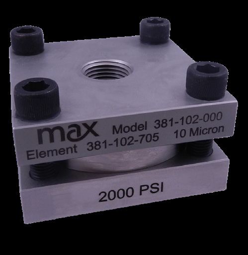
Electrical
Environment: The transmitter is rated to operate in the 5 C to 90 C fluid temperature range at an ambient temperature
range of 5 C to 80 C. If the ambient temperature rises above 55 C (130F), the maximum fluid temperature at the flow
meter is de-rated as shown in the chart below.

                                            P234 Transmitter Permissible Temperatures
                                                       100

                              Ambient Temperature °C   80

                                                       60
                                                        55

                                                       40             Standard

                                                       20

                                                         5
                                                        0
                                                             5               50           90 100
                                                                 Process Temperature °C
Transmitter installation is via a 5-pin, M12 style Turck connector. The connector is sealed to the body at the factory and
is ready for use. If your installation requires conduit, PG-9 to conduit adapters are available from third parties. If using a
conduit setup, use a sealed conduit connection and conduit stop to protect the electronics from moisture and corrosives.
Follow the wiring diagrams on page 4 for replacing the 5-pin Turck connector with your own wiring.

             WARNING: Electrical shock hazard. Serious or fatal injury may occur.
   !         Installation/Removal should only be completed by trained and authorized personnel.

             WARNING: The P234 is not designed for use in hazardous locations. Adapting the meter to
   !         a conduit connection does not protect the system in a hazardous location. Do not use in a
             hazardous location as death or severe injury may occur.

             CAUTION: Verify transmitter output type (Analog or Frequency) before wiring.
   !         Inappropriate wiring could result in damaging the circuit.
             Installation/Removal should only be completed by trained and authorized personnel.

P234 User Manual Rev2020A - © 2008 - 2020		                              3                                 P234-USEMAN-REV2018A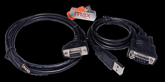
Frequency Output Transmitters (Versions ending with N/2)
            4       3                       Turck®
                5                          Connector
                                PCA               Mating Cable
            1       2                     Pin #   Wire Color
                                Label

 Power (+5 to 26 Vdc)           V+          1     Brown
 Common                         Com        4      Black
 Pulse Output                   Ph A       2      White

 Output Phase B (Quad only)     Ph B       5      Grey

 Case Ground                    Case       3      Blue

                                                                                                 V+
                                                                                                                              PLC
Current Sinking Wiring (Versions ending with S/2)
                                                                                                            V+
                                                                                                                              Digital
                                                                                                      0V                      Input
A current sinking device uses the transmitter’s transistor output to act as a                               Out

switch. A positive DC voltage must be applied to the transmitter's output pin                         Turck Pin #2 on
                                                                                                      Industrial housings
(#2). When the pulse output is triggered, this voltage will be grounded to zero
volts by the transmitter. Warning: Use a 5k ohm resistor to limit current if your
system does not have any other means to limit the current into the transmitter.
                                                                                                      Transmitter

Current Output Transmitters (Versions ending with A/2 or B/2)
Voltage Output Transmitters (Versions ending with C/2 or D/2 )
        4       3                         Turck®
            5                            Connector
                        PCA               Mating Cable
        1       2               Pin #     Wire Color
                        Label

  Power *               V+           1    Brown
  Common                Com       4       Black
  Signal Output (+)     Sig       5       Grey
  Signal Output (—)**   Ret       2       White
  Case Ground           Case      3       Blue

Voltage or Current Analog Transmitters (Models ending with A/2, B/2, C/2 or D/2)
* Analog transmitters with part numbers ending in A/2 or C/2 are 24Vdc power. Part numbers ending in B/2 or D/2 are
12Vdc power.
** To minimize signal noise, analog output transmitters are fully isolated. If your PLC does not ground the negative
signal input, there is a risk of a ground shift that could drive the signal out of the range of detection. To prevent this from
occuring please consider installing a 10k pull down resistor between Common and Signal Output (-).

P234 User Manual Rev2020A - © 2008 - 2020		                      4                                                  P234-USEMAN-REV2018A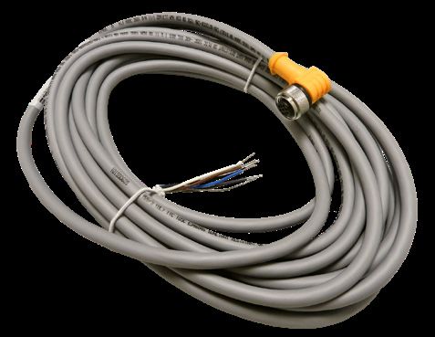
Field Compensation of Transmitter
The transmitter LED on the P234 top cover indicates a functioning system when it is producing a pulse output or
detecting magnet travel in the meter.
An alternating blue/green LED indicates that the circuit is detecting a magnet and provides an output signal.
A steady or flashing red LED indicates a problem with the transmitter PCA. Contact Max Machinery to have your P234
flow meter refurbished.
The Compensation Algorithm adjusts for variations in Hall sensor and flow meter characteristics to provide a stable,
undamped output frequency that accurately represents the instantaneous flow rate. This feature is factory set when the
meter is assembled. If the transmitter PCA is replaced or reset, the compensation can be performed via the gold PCA
button or through the software kit.
The only method of altering additional factory set parameters of the meter is through the Interface Software Kit, part
number SFT-KIT-001. Pulse Output Scaling, Analog Output Limits and Scaling, Signal Filtering Options and Compensation
settings are the adjustable variables.
WARNING: Electrical shock hazard. Serious or fatal injury may occur.
! Access should only be completed by trained and authorized personnel.
CAUTION: Before opening/accessing the electronics lid, make sure the top of the P234
! meter and surrounding components are dry and no moisture or fluids can contact the
electrical components. Non-warranty damage may occur.
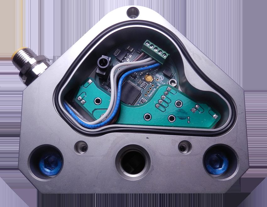
Instructions to access the gold PCA button and software serial port:
- Unscrew the captured philips head screws on the electronics lid.
- Remove and set aside the lid with o-ring seal.
- Optional: follow instructions for SFT-KIT-001 to connect to software serial port.
- Follow field compensation instructions on page 6.
- To reinstall, ensure the o-ring seal is firmly seated. Assembly is then the reverse of disassembly.
Software Serial Port
LED
Gold PCA Button
O-ring in Groove Lid with
Captured Screws
LED Window
P234 User Manual Rev2020A - © 2008 - 2020 5 P234-USEMAN-REV2018A
Field Compensation of Transmitter Continued

When a transmitter PCA is replaced or reset in the field, the compensation routine should be performed to optimize the
performance of the system. This routine requires a steady flow rate between 35 cc/min and 2000 cc/min. The flow meter
being compensated must not be used for system flow rate feedback control during this process. The transmitter output
is disabled during the compensation routine.

If you are unable to run a stable flow in the field, send your meter in to Max Machinery for calibration.

For the P234, the compensation routine is as follows:

1. Place your system in ‘manual’ mode or run in ‘open loop’ mode with no flow meter feedback control. Max
   transmitter output shuts off during field compensation routine. Loss of signal to ‘closed loop control’ modes can affect
   the flow stabilization of the system and the compensation of the Max meter.
2. Stabilize the flow rate between 35 cc/min and 2000 cc/min.
3. Activate the compensation routine:
     A - When using the software via the serial port connection, select ‘field compensation’ in the software.
         OR
     B - If NOT using software, push the Gold PCA Button using a non-conductive tool.
4. The blue/green LED will change to solid blue for 4 revolutions of the meter. See table LED Functions on next page for
   duration of compensation process. Duration is dependent upon flow rate.
5. A green LED light indicates a successful update of the compensation, a red LED light indicates the new compensation
   failed. Additional information is available through the interface software.
6. Return your system to ‘operating’ mode or restore settings to allow for feedback control.

P234 User Manual Rev2020A - © 2008 - 2020		                   6                                             P234-USEMAN-REV2018A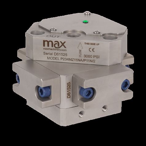
LED Functions
 Normal Operation
 STATUS                                LED                           ACTION
 Functioning - System Not Flowing      Blue or Green Steady          Meter is functioning, but no flow is detected in
                                                                     the system.

 Functioning - System Flowing          Blue / Green alternating      Meter is functioning, flow is occuring in the
                                       colors                        system. Note: At high flow rates, the alternating
                                                                     Blue/Green flashes may appear as a single
                                                                     steady color.
 Meter Malfunction                     Red Steady                    Refurbish Meter.

 No Power / Meter Failure              No Light                      - Verify power supply to meter.
                                                                     - Verify wiring follows diagrams on page 4.
                                                                     - If power and wiring are verified, refurbish
                                                                     meter.

 Compensation via Interface Software Kit or Gold PCA Button
 STATUS                                LED                           ACTION
 Compensate button pushed/clicked      Blue Steady                   - Steady light for 4-5 revolutions of meter.
 Compensation Succeeded                Green Steady                  - Steady light for 5 seconds.
                                                                     - Software will show “Success” on screen.

 Compensation Failed                   Red Steady                    - Steady light for 5 seconds.
                                                                     - Software wil show “Flow too low/ too high/
                                                                     unstable” on screen.
 Note: Revolutions of meter are dependent on expected fluid flow rate. Per the P234 specifications, 4-5 revolutions of
 the meter take approximately the following amount of time at the stated flow rates:
 35 cc/min (minimum compensation flow rate) - 90 seconds
 100 cc/min                                    - 35 seconds
 1000 cc/min                                   - 1 5 seconds
 2000 cc/min (maximum meter flow rate)         - 10 seconds
 If compensation fails, restart the compensation process. When using the Interface Software Kit, follow instructions
 provided to correct errors prior to attempting compensation again. If problems persist, contact Max Machinery at
 707-433-2662 or at www.maxmachinery.com.

P234 User Manual Rev2020A - © 2008 - 2020		               7                                            P234-USEMAN-REV2018A
Specifications
SPECIFICATIONS
Flow Range 1 to 2000 cc/min
Accuracy (1 cP) ± 0.4% of reading over a 100:1 range
Maximum Operating Pressure 3000 psi (210 bar)
Weight 4.1 kg
Recommended Filtration 10 micron
Port Size(s) 1/4 inch NPT or G 1/4-19 BSPP
Fluids Most aqueous based fluids with a pH between 4 and 12
MATERIALS OF CONSTRUCTION
External Stainless steel, type 316, type 304; Blue Xylan 316 fastners;
Polycarbonate LED cover - avoid contact with solvents
Wetted Stainless steel, type 316; Graphite; PEEK; Nickel Carbide
O-Rings Standard: Viton®
Optional: Teflon®, Perfluoroelastmer
FREQUENCY TRANSMITTER
Output Signal Standard: 5 Vdc, single phase
Optional: Quadrature 5 Vdc, two phase
Current sinking, 20 mA max., single phase
K-Factor Single Phase: 180 pulses/cc
Two Phase: 360 pulses/cc, 4x decoded
(90 pulses/cc/phase, 1x decoded)
Power Supply Requirements 5-26 Vdc @ 30ma
Ambient Operational Range 5°C to 80°C
Metered Liquid Temp Range 5°C to 90°C
(based on 20° ambient)
ANALOG TRANSMITTER
Output Signal Any range of ± 10V or ± 20mA linearized and damped
with anti-dither protection
Power Supply Requirements 12Vdc @ 90 mA, 24Vdc @ 45 mA
Ambient Operational Range 5°C to 80°C
Metered Liquid Temp Range 5°C to 90°C
(based on 20° ambient)
P234 User Manual Rev2020A - © 2008 - 2020 8 P234-USEMAN-REV2018ASpecifications P234MEKP-### Variants
SPECIFICATIONS
Flow Range 1 to 500 cc/min
Accuracy (1 cP) ± 0.4% of reading over a 25:1 range
Maximum Operating Pressure 3000 psi (210 bar)
Weight 4.1 kg
Recommended Filtration 10 micron
Port Size(s) 1/4 inch NPT or G 1/4-19 BSPP
Fluids Most aqueous based fluids with a pH between 4 and 12,
specifically suited for methyl ethyl ketone peroxide
MATERIALS OF CONSTRUCTION
External Stainless steel, type 316, type 304; Blue Xylan 316 fastners;
Polycarbonate LED cover - avoid contact with solvents
Wetted Stainless steel, type 316; Graphite; PEEK; Expanite hardened
316SS
O-Rings Standard: Viton®
Optional: Teflon®, Perfluoroelastmer
FREQUENCY TRANSMITTER
Output Signal Standard: 5 Vdc, single phase
Optional: Quadrature 5 Vdc, two phase
Current sinking, 20 mA max., single phase
K-Factor Single Phase: 180 pulses/cc
Two Phase: 360 pulses/cc, 4x decoded
(90 pulses/cc/phase, 1x decoded)
Power Supply Requirements 5-26 Vdc @ 30ma
Ambient Operational Range 5°C to 80°C
Metered Liquid Temp Range 5°C to 90°C
(based on 20° ambient)
ANALOG TRANSMITTER
Output Signal Any range of ± 10V or ± 20mA linearized and damped
with anti-dither protection
Power Supply Requirements 24Vdc @ 45 mA
Ambient Operational Range 5°C to 80°C
Metered Liquid Temp Range 5°C to 90°C
(based on 20° ambient)
P234 User Manual Rev2020A - © 2008 - 2020 9 P234-USEMAN-REV2018ADimensions 2.40
3.3
3.12 OVERALL
PORT TO PORT HEIGHT
DISTANCE
2.61
.35
1.125
2.95
1/4-20 UNC 4.61
MOUNTING HOLES
TURCK 5-PIN / PG-9
CONDUIT CONNECTION
2.400
LED INDICATOR INLET
PORT
OUTLET
PORT
4.610
4.610
Charts
P234 User Manual Rev2020A - © 2008 - 2020 10 P234-USEMAN-REV2018APart Matrix
an ISO 9001:2015 certified company
Positive Displacement Flow Meters
Piston Type, P-Series 3000 psi (210 bar) rated, Water Based Fluids
Flow Meter Selections Transmitter Selections
Model # MZ NA / 1 1 / 2 - Non-Standard Options
Bi-Directional Cal: BID
2 Transmitter Type
Max Flow Range Output Type
2 Liters/Min P234 MZ A A 4-20mA Output - Powered by 24 Vdc
A B 4-20mA Output - Powered by 12 Vdc
A C 0-10 Volt Output - Powered by 24 Vdc
A D 0-10 Volt Output - Powered by 12 Vdc
P N 5V Pulse/Freq. - Powered by 5-26 Vdc
Q N 5V Quadrature - Powered by 5-26 Vdc
P S Current Sinking, Single Phase
Pressure Temperature Rating
3000 psi (210 bar) MZ 1 90°C Industrial
Fluid Connection Electrical Connection
NPT 1 1 Industrial, Turck® Connector
G-Type / BSPP 6
Seal Selection Signal Type
Viton® - FKM 1 P Pulse
Teflon® - PTFE 3 A Analog
Perfluoroelastomer - FFKM 5 Q Quadrature
Options
None NA
Product includes single directional calibration, bi-directional
calibrations for Analog and Quadrature devices are optional.
Max Machinery, Inc.
33A Healdsburg Avenue maxmachinery.com
Healdsburg, CA 95448 T + 1 707.433.2662 ©2008-2020
P234 User Manual Rev2020A - © 2008 - 2020 11 P234-USEMAN-REV2018APart Matrix
an ISO 9001:2015 certified company
Positive Displacement Flow Meters
Piston Type, P-Series 3000 psi (210 bar) rated, MEKP Based Fluids
Part Number Fluid Connection Transmitter
P234-MEKP-001 NPT Pulse: 5V Frequency. - Powered by 5-26 Vdc
P234-MEKP-002 NPT Pulse: Current Sinking, Single Phase
P234-MEKP-003 NPT Quadrature: 5V A/B signal - Powered by 5-26 Vdc
P234-MEKP-004 NPT Analog: 4-20mA Output - Powered by 24 Vdc
P234-MEKP-005 NPT Analog: 0-10 Volt Output - Powered by 24 Vdc
P234-MEKP-010 BSPP Pulse: 5V Frequency. - Powered by 5-26 Vdc
P234-MEKP-020 BSPP Pulse: Current Sinking, Single Phase
P234-MEKP-030 BSPP Quadrature: 5V A/B signal - Powered by 5-26 Vdc
P234-MEKP-040 BSPP Analog: 4-20mA Output - Powered by 24 Vdc
P234-MEKP-050 BSPP Analog: 0-10 Volt Output - Powered by 24 Vdc
P234-MEKP-100 SAE Pulse: 5V Frequency. - Powered by 5-26 Vdc
P234-MEKP-200 SAE Pulse: Current Sinking, Single Phase
P234-MEKP-300 SAE Quadrature: 5V A/B signal - Powered by 5-26 Vdc
P234-MEKP-400 SAE Analog: 4-20mA Output - Powered by 24 Vdc
P234-MEKP-500 SAE Analog: 0-10 Volt Output - Powered by 24 Vdc
-BID option: Product includes single directional calibration, bi-directional
calibrations for Analog and Quadrature devices are optional.
All options or variations not listed above are standard across all meter variants. All P234-
MEKP meters come with Perfluoroelastomer seals, Industrial housing rated to 90 C, and
Turck M12 connector.
Max Machinery, Inc.
33A Healdsburg Avenue maxmachinery.com
Healdsburg, CA 95448 T + 1 707.433.2662 ©2008-2020
P234 User Manual Rev2020A - © 2008 - 2020 12 P234-USEMAN-REV2018AAvailable Accessories
Accessories to support your system and simplify your installation and maintenance are available direct from Max.
Request yours when you order your flow meter. See the website for information and options.
Interface Software Kit
Part # Description
SFT-KIT-001 USB drive transmitter programming software and serial cable.
The following adjustments may be made to the signal output:
Pulse Output Scaling, Analog Output Limits and Scaling, Signal
Filtering Options and Compensation settings.
Cables
Part # Description
181-294-060 7 meter cable - 5-pin Turck® to wire
181-294-061 15 meter cable - 5-pin Turck® to wire
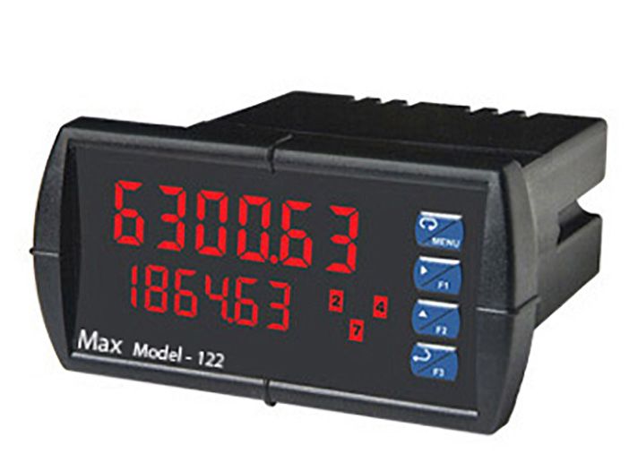
Model 122 Combination Rate Indicator/Totalizers
110/220 Vac powered (frequency input)
Model Description
122-200-000 Panel mount indicator with dual-line, 6-digit display (0.6” and
0.46”). Produces an isolated 4-20mA analog output. Provides 24
Vdc transmitter power. Can be programmed to show rate, total
and/or grand total. Initial programming included as default or
customer specified values.
381 Series Filters and Filter Elements
Model Description
381-102-000 Inline filter with 10 micron element included. O-rings options
available to match your flow meter and system requirements.
P234 User Manual Rev2020A - © 2008 - 2020 13 P234-USEMAN-REV2018ATroubleshooting and Service Request
Problem Corrective Action
No Flow through meter or high pressure drop across meter
Solidified material blocking rotation Heat meter to melt material. Do not exceed maximum
meter operating temperature.
Debris damage or internally clogged Refurbish meter.
Meter broken Refurbish meter.
Fluid passes through meter, but no flow is indicated
Transmitter cable or conduit cable incorrectly wired Verify DC power is present at the PCA. Use a multi-meter to
measure the transmitter output independent of the display
or PLC.
Meter not turning Refurbish meter.
Indicated flow does not agree with expected readings
Air in the line Air bubbles displace the meter just like a liquid. If
you see over-reporting, purge all air from lines.
Indicator not calibrated properly Verify K-Factor for the meter in use and compare
this value to the setting used in the display.
Excessive reverse flow in system Max transmitters’ anti-dither function buffers up to 1
revolution of reverse flow. An incorrect flow total can be
reported if the system reverse flow is greater than 1 meter
revolution.
Additional Information Available
MMI provides refurbishment and calibration services. For more details or to submit your Service Request, go to
https://www.maxmachinery.com/services/.
Additional information about our products, including STEP files and Sample Calibration sheets, may be found on our
website at https://www.maxmachinery.com/downloads/.
MMI products are covered under our standard manufacturer’s warranty. Details may be found at
https://www.maxmachinery.com/warranty/.
Max Machinery, Inc., 33A Healdsburg Avenue, Healdsburg, CA 95448 USA
707.433.2662 | www.maxmachinery.com
P234 User Manual Rev2020A - © 2008 - 2020 14 P234-USEMAN-REV2018AYou can also read