PATIO AWNING INSTALLATION - Retractable Fabric Awnings Create an Instant Covered Patio! - Craft Bilt
←
→
Page content transcription
If your browser does not render page correctly, please read the page content below
PATIO AWNING
INSTALLATION

  Retractable Fabric Awnings…
 Create an Instant Covered Patio!

 53 Souderton-Hatfield Pike • Souderton, PA 18964
 215-721-7700 • fax 215-721-9338
 www.craftbilt.com
Betterliving Model Numbers and Names
     Model 1 – Estate
     Model 2 – Slim-Fit
     Model 3 – XLP
     Model 4 – Manor
     Model 5 – EKO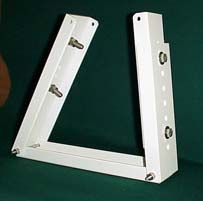
TABLE OF CONTENTS
Section A: Pre-Installation Checklist
Tool List …………………………………………………………………………………………….………….. Page 3
Determine Wall Mounting Height and Clearance Required……………………………………..…...…... Page 4
Determine Mounting Bracket Locations ……………………………………………………………………. Page 5
Introduction (Unpacking, Preparing to Install, Pressure Treated Wood Warning) …………………….. Page 6
Section B: Awning Installation Instructions - Ekō, Estate, Estate Slim-Fit, Manor
Mounting Board on Frame House with Siding or Stucco …..………………………...………………….. Page 7
Wall Mounting on Brick Surface …………………………………………………………………………….. Page 9
Soffit Mounting Using a Mounting Board…………………………………………………………….…….. Page 10
Roof Mount Using a Mounting Board ……………………………………………………….……………... Page 12
Section C: Place Awning on Brackets
Place Awning on Brackets …………………………………………………………………...………….….. Page 15
Section D: Operational Information
Making Electrical Connections …………………………………………………………….……………..…. Page 16
Adjusting the Awning Pitch - Estate, Estate Slim-Fit and Manor …...……………………………….….. Page 16
Adjusting the Front Profile ……………………………………………………………………………….…. Page 17
Operating the Estate, Estate Slim-Fit and Manor ….……………………………………………………… Page 18
Adjusting the Awning Pitch - Ekō ………………...…...…………………………………………………… Page 18
Operating the Ekō ……....………………………………………………………………………….………… Page 19
Appendices:
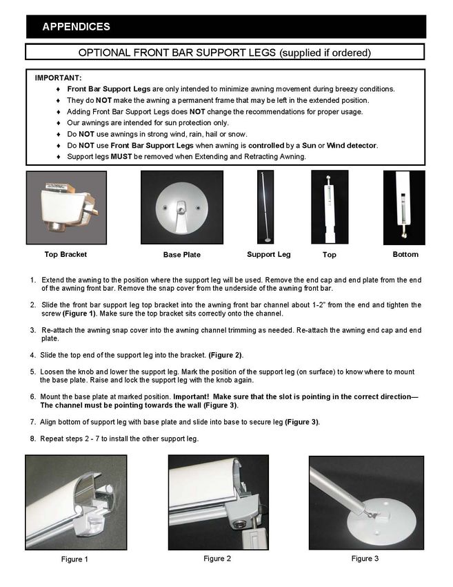
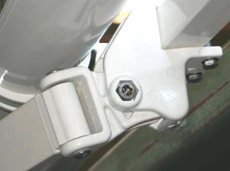
Optional Front Bar Support Legs ……………………………………………………………………………. Page 20
Mounting Bracket Drilling Template - Estate, Estate Slim-Fit, Manor: …..…...………………………… Page 21
Soffit Mount Bracket Drilling Template - Estate, Estate Slim-Fit, Manor: …...…………………………. Page 22
Mounting Bracket Drilling Template - Ekō ..………………………….….………………………………… Page 23
Soffit Mount Bracket Drilling Template - Ekō .………….………………..……………………………….. Page 24
Manual updated 6-18-10.
All information contained herein subject to errors and omissions
2TOOL LIST
Tools listed below are required to install and service all models of Craft-Bilt Manufacturing fabric awnings.
Not every tool is required for every installation:
▪ 3/8" reversible drill
▪ 1/8”, 3/16”, 1/4”, 3/8”, 1/2” with 3/8” shaft high speed drill bits
▪ 1-1/4” speed bore drill bit
▪ 3/8” masonry drill bit
▪ 1/2” impact wrench
▪ 1/2” drive sockets 7/16”, 9/16” and 3/4”
▪ 1/2” ratchet
▪ Open end wrench 10mm, 13mm, 17mm (thinner the better)
▪ Sockets, metric: 10mm, 11mm, 13mm, 17mm*
▪ Allen wrenches, metric: 3mm, 4mm, 5mm, 6mm, 8mm*
▪ Philips head screw driver
▪ 4-1/2” angle grinder
▪ 4” diamond blades
▪ Circular saw
▪ Eye protection
▪ Utility knife
▪ Tape measure
▪ 4’ Level
▪ Chalk line
▪ Soap stick or piece of chalk
▪ 40 mm Square bar (available from Craft-Bilt - #73COSB0123WH) - optional - in lieu of chalk line
▪ Stud finder
▪ Somfy™ Motor Tester Cable (available from Craft-Bilt - #706020086)
▪ Aluminum Brake (if not using vinyl pre-formed profile)
▪ Rubber mallet
▪ Clamps (2)
▪ Caulk gun
▪ Silicone caulk
▪ Plastic roof cement
▪ Touch up paint
▪ Proper ladders
▪ Awl
▪ Flat bar
ADDITIONAL HARDWARE AND MATERIALS
The following hardware or materials may be required, depending on your installation:
▪ 2” x 8” kiln dried lumber for mounting board on house wall application
▪ 1/2” x 4” hex sleeve anchor, for masonry house wall application
▪ 5/16” x 4” galvanized lag screws, for installing mounting board to studs in house wall (available from Craft-Bilt in bags
containing 25 lags and 25 washers (CBM # 73COFS08XXXX)
▪ 1/4” galvanized washers
▪ 1/2” galvanized washers (for shimming)
▪ Trim nails
▪ 3” wood screw
▪ 1/2” x 2” galvanized lags to lag awning bracket to mounting board (bottom hole)
▪ Vinyl capping or aluminum coil to cover mounting board. Vinyl capping available from Craft-Bilt in white or sandstone
196” lengths (CBM# 73EXFL0116 WH or ST)
▪ 1/2” electrical bushing (motorized models only)
*Use of non-metric tools will invalidate warranty.
3DETERMINE WALL MOUNTING HEIGHT & CLEARANCE REQUIRED
EKŌ, ESTATE, ESTATE SLIM-FIT & MANOR
Table 1
Recommended Minimum Wall Mounting Height* Diagram A
Ekō Estate Manor Slim-Fit
4' 11" 95'' 99'' 100"
6' 7" 98'' 102'' 103"
6' 11" 99''
PROJECTION
8' 2" 100'' 105'' 105"
8' 6" 101''
9' 10" 102'' 109'' 107"
10' 2" 103''
11' 6" 105'' 112'' 110"
13' 1" 107'' 115'' 112"
*Height calculated using recommended front bar height of 80".
Wall Mounting Height includes 8" for Mounting Board or Cassette.
Fabric Valance NOT included in calculations.
Minimum Awning Drop
EKŌ, EKŌ,
Table 2 EKŌ, Estate, Manor
Estate Estate
Awning Pitch 7° 10° 15° 20° 25° 30° 35°
Estate & Manor: 4' 11" 15'' 19'' 24'' 29'' 33'' 38'' 42''
Estate & Manor: 6' 7" 18'' 22'' 29'' 35'' 42'' 48'' 53''
PROJECTION
EKŌ: 6' 11" 19" 24" 31" 39" 46" 53" 59"
Estate & Manor: 8' 2" 20'' 25'' 33'' 42'' 50'' 57'' 64''
EKŌ: 8' 6" 21" 27" 36" 46" 54" 62" 70"
Estate & Manor: 9' 10" 22'' 29'' 39'' 49'' 58'' 67'' 75''
EKŌ: 10' 2" 24" 31" 41" 53" 63" 72" 81"
Estate & Manor: 11' 6" 25'' 32'' 43'' 56'' 67'' 77'' 87''
Estate & Manor: 13' 1" 27'' 35'' 50'' 60'' 75'' 86'' 99''
The Drop dimension is measured from the top of the awning
at the wall to the bottom of the front bar when projected.
Diagram B
IMPORTANT ESTATE SLIM-FIT
CLEARANCE INFORMATION
The mounting area required for an Estate Slim-Fit
Awning is an additional 4 1/2” below the mounting
board for a total of at least 12 1/2” (Diagram B).
4DETERMINE MOUNTING BRACKET LOCATIONS
EKŌ, ESTATE, ESTATE SLIM-FIT & MANOR
Diagram C - BRACKET LAYOUT AS SEEN FROM BACK OF AWNING
1. Lay the awning in front of, and parallel to the installation surface. Measure ALL obstructions on the back of the awning
(e.g. end brackets, shoulder assemblies, hood mounting Brackets, fabric tray brackets and bottom cover brackets).
2. After capping has been applied to the mounting board, mark locations of ALL obstructions on Mounting Board or
Mounting Surface (brick only).
3. Determine the Wall Bracket locations.
▪ Outer wall brackets must be installed as close to the shoulder assembly as possible on the outboard side.
▪ Mount additional wall brackets at equal intervals in spaces allowed.
SOFFIT MOUNT BRACKET
DRILLING TEMPLATE
Diagram D
Mounting Bracket templates are in the
Appendix section of this manual.
Remove this page and use the template
to determine the vertical location on the
Mounting Board.
NOTE: Use SOFFIT TEMPLATE for Soffit
Mounting ONLY.
5INTRODUCTION
Thank you for choosing a Craft-Bilt Manufacturing retractable fabric awning.
For this awning to operate as designed, it must be properly installed. Please follow these instructions exactly and use all
the components and fasteners, as described.
Retractable awnings are intended as protection against sun only. Do not use in strong wind, rain, hail or snow.
Every home improvement project should begin with safety precautions. Always wear eye protection and follow the safety
instructions that came with your tools. A typical installation requires at least two or three people, depending upon the
weight of the awning and accessibility at the site.
UNPACKING
Be careful of staples when opening the shipping carton.
The awning is wrapped and held in place with bubble wrap. Lift the awning at both ends, remove from the box and lay
on a flat, level surface. Keep the carton and bubble wrap for later use.
Be careful not to cut the awning fabric when removing wrapping. Clean hands of grease/dirt before handling the fabric.
With the awning you will find: hardware, power cords, brackets, warranty package and instructions, etc.
Check the awning against the packing list. Notify Craft-Bilt Customer Satisfaction Department at (215) 721-7700 if you
feel there are any discrepancies.
PREPARING TO INSTALL
The awning is shipped assembled. Please follow installation instructions for your awning type and mounting situation.
The awning can be installed on a Wall, Soffit or Roof. Lay the awning in front of, and parallel to, the installation surface.
Determine the location for your awning and remove all downspouts, lights, boxes, vents and other obstructions. Relocate
hanging objects from inside wall during installation.
All installations use two or more mounting brackets supplied with the awning. It is critical that all brackets are
mounted level, plumb and on the same surface plane. Misaligned brackets will affect the appearance and
functioning of the awning. A patio awning template is included with these instructions to help position brackets on a
mounting board when required.
Refer to the appropriate section for your installation.
NOTE: There is no approved method for mounting the awning to a fascia. Only professional installers should attempt to
install awnings on structures with stone, cedar shake, or EIFS (exterior insulated finish system) exteriors.
PRESSURE TREATED WOOD WARNING
Pressure treated lumber should NOT be used. Pressure treated lumber can be corrosive to fasteners, aluminum and
anchors which would cause serious harm if failure occurs. See your local lumber supplier for details.
6SECTION B
MOUNTING BOARD ON FRAME HOUSE WITH SIDING OR STUCCO
EKŌ, ESTATE, ESTATE SLIM-FIT & MANOR
1. Craft-Bilt recommends using kiln dried 2 x 8 lumber for the mounting board covered with vinyl capping profile (available from
CBM # 73EXFL0116WH/ST) or brake-formed aluminum trim coil. (See Pressure Treated Wood Warning on page 6.)
2. Determine the Wall Mounting Height and Clearance required. (See detailed information on page 4.) The recommended
minimum front bar height is 80”. Installation below the recommended height is possible when necessary, or at the owner’s
discretion.
3. Cut the mounting board to length; awning width plus 2”.
4. Determine Mounting Bracket locations and mark all obstruction locations on the board. (See detailed information on page 5.)
5. Mark all four corners of the mounting board on the wall; awning length plus 2”. Add 1/4” of length and height for aluminum
trim coil clearance (if it is being used for capping). Snap chalk line from corner to corner making a box. Make sure your lines
are level and plumb (Figure A).
6. Cut an opening in the siding for the mounting board (Figure B). A 4” Grinder with diamond blade works well on aluminum
and vinyl siding.
7. Mounting board MUST BE fastened to studs every 16" or 24", depending on spacing. Plywood sheathing will NOT support the
awning. Use a stud finder to locate all the studs within the exposed area (Figure C). If there is insulation or foam use an awl
to probe for the studs; if there is plywood sheathing, drill test holes using a 1/16" drill bit.
8. Find and mark the stud’s centers above the siding cut out. Caulk the test holes when done.
Figure A Figure B Figure C
9. If using “J” Channel, install it now before temporarily installing the mounting board. Standard flashing practices must be
followed.
10. Temporarily attach mounting board to wall using 3" wood screws. Mounting Board must be level. Check using carpenter’s
level. Be sure the mounting board face with the obstruction marks are showing. Transfer stud center marks onto the
mounting board.
11. Drill 3/16” pilot holes directly through mounting board into the centers of all marked studs (Figure D). Use 1-1/4” Speed Bore
to countersink holes 1/2” (Figure E). TWO HOLES ARE REQUIRED ON EACH STUD AT THE TOP AND BOTTOM OF
THE BOARD (Figure F).
Figure D Figure E Figure F
7SECTION B
12. Attach mounting board securely using 5/16” x 4” hex head lag screws and 5/16” washers (CBM # 73COFS08XXXX,
supplied with order if specified). Drive lags through pre-drilled holes using a power tool or socket wrench with 1/2”
socket. Do not over tighten.
13. Transfer bracket location marks from mounting board onto house wall.
14. Wrap mounting board with vinyl capping (available from CBM # 73EXFL0116WH/ST) or brake-formed aluminum trim
coil. Silicone caulk and/or finishing channel MUST be used to seal around mounting board. Standard flashing
practices must be followed. Transfer bracket location marks from house wall onto capping..
15a. For Estate, Manor and Slim-Fit Awnings: select template in Appendix A.
• Use the selected template to determine the vertical bracket location on the mounting board.
• Fold template along fold line at bottom.
• Place on mounting board.
(Do NOT use the template in Appendix A if using Craft-Bilt vinyl capping profile (CBM t# 73EXFL0116WH/ST;
as fastener location indicator lines are pre-formed in the vinyl capping.)
• Drill 1/4" pilot holes for all brackets (Figure G).
15b. For Ekō Awnings: select template in Appendix C.
• Use the selected template to determine the vertical bracket location on the mounting board.
• Fold template along fold line at bottom.
• Place on mounting board.
• Drill 1/4" pilot holes for all brackets (Figure G).
16a. For Estate, Manor and Slim-Fit Awnings:
• Attach brackets using 1/2" x 2" galvanized lag screws and 1/2” washers (supplied with awning).
• Use socket wrench to drive the screws (Figures H & I). Do not over tighten.
• Warning - Over tightening lags can cause wood to split and awning installation to fail.
• Brackets must be mounted level and plumb.
• Use a chalk line to be sure all brackets are level and on the same plane.
• (Shimming with 1/2” galvanized washers under brackets may be needed.)
• Misaligned brackets will affect the awning appearance and functioning.
16b. For Ekō Awnings: select the template in Appendix C.
• Attach brackets using 3/8" x 4" galvanized lag screws and 3/8" washers (supplied with the awning).
• Use a socket wrench to drive the screws. (Figures H & I).
• Do not over tighten.
• Warning! Over tightening the lags can cause the wood to split and your awning installation to fail.
• Brackets must be mounted level and plumb.
• Use a chalk line to check that the brackets are level and on the same plane.
• Shimming with 3/8” galvanized washers under brackets may be needed.
• Misaligned brackets will affect appearance and functioning of awning.
For Awning Installation — Refer to Section C.
Do Not
Over
Tighten!
Figure G Figure H Figure I
8SECTION B
WALL MOUNTING INSTALLATION ON BRICK SURFACE
EKŌ, ESTATE, ESTATE SLIM-FIT & MANOR
1. Mounting brackets can be installed directly on solid brick using 1/2” x 4” hex sleeve anchor.
2. Determine the Wall Mounting Height and Clearance required. (See detailed information on page 4.) The recommended
minimum front bar height is 80”. Installation below the recommended height is possible when necessary, or at the owner’s
discretion.
3. Determine Mounting Bracket locations and mark all obstruction locations. (see detailed information on page 5.)
4. Mark the Mounting Bracket locations on wall surface.
5. Hold the first bracket plumb against brick and carefully mark upper and lower fastening holes.
6. Remove bracket and drill top mounting hole using a 1/2" diameter masonry bit.
7. Use carpenter’s level to ensure bottom hole is plumb with top hole before drilling. Drill bottom pilot hole.
8. Attach bracket using 1/2” x 4” hex sleeve anchor.
9. After the first bracket is installed use a level and chalk to mark a horizontal line on the wall the full width of the awning.
10. Repeat steps 5 - 8 to mount the opposite end mounting bracket.
11. Space the remaining brackets equally in between the outer mounting brackets.
12. Repeat steps 5 - 8 to fasten each remaining bracket. Misaligned brackets will affect appearance and functioning
of awning.
For Awning Installation — Refer to Section C.
9SECTION B
SOFFIT MOUNTING USING A MOUNTING BOARD
EKŌ, ESTATE, ESTATE SLIM-FIT & MANOR
IMPORTANT NOTES:
♦ ONLY STRUCTURAL SOFFITS will support an awning.
♦ Do NOT attempt a Soffit installation if the Soffit is not structural.
♦ Before you consider a Soffit mount installation, refer to the Awning Drop Chart (page 4), making sure desired
mounting and front bar heights are obtainable.
♦ SOFFIT ADAPTERS ARE OPTIONAL and they must be ordered separately as needed.
Order one Soffit adapter per mounting bracket required for awning.
♦ A Mounting Board is recommended. 1” lumber or plywood WILL NOT SUPPORT the awning.
♦ If Soffit is vented, DO NOT OBSTRUCT the VENTS - Consider alternate mounting method.
1. Craft-Bilt recommends using kiln dried 2 x 8 lumber for the mounting board covered with vinyl capping profile (available from
CBM # 73EXFL0116WH/ST) or brake-formed aluminum trim coil (See Pressure Treated Wood warning on page 6.)
2. Cut mounting board to desired length – total awning width plus 2”.
3. Determine Mounting Bracket locations and mark all obstruction locations on the board. See detailed information on
page 5.
4. Mark all four corners of the mounting board on the Soffit (awning length plus 2”). Add 1/4” of length and height for aluminum
trim coil clearance (if it is being used for capping). Snap chalk line from corner to corner making a box. Make sure your lines
are parallel with the house wall or fascia board.
VINYL or ALUMINUM SOFFIT MATERIAL ONLY:
♦ Cut an opening in the Soffit material for the mounting board.
A 4” grinder with diamond blade works well on aluminum and vinyl siding.
♦ Mounting board MUST BE fastened to Soffit supports or rafters every 16" or 24", depending on spacing.
Plywood sheathing will NOT support the awning. Find all Soffit supports or rafters within the exposed area.
If there is insulation or foam use an awl to probe for the Soffit supports or rafters
If there is plywood sheathing, drill test holes using a 1/16" drill bit.
5. Find the soffit supports or rafter tail centers and mark them outside the chalk line, or the previously cut opening.
Caulk the test holes when done.
6. If using “J” Channel, install it now before temporarily installing the mounting board. Standard flashing practices must be
followed.
7. Temporarily attach mounting board to soffit using 3" wood screws. Mounting Board must be level. Check using carpenter’s
level. Be sure the mounting board face with the obstruction marks are showing. Transfer soffit support or rafter tail center
marks onto the mounting board.
8. Drill 3/16” pilot holes directly through mounting board into the centers of all marked soffit supports and rafters. Use 1 1/4”
Speed Bore to countersink holes 1/2”. TWO HOLES ARE REQUIRED ON EACH SOFFIT SUPPORT OR RAFTER AT THE TOP
AND BOTTOM OF THE BOARD.
9. Attach mounting board securely using 5/16” x 4” hex head lag screws and 5/16” washers (CBM # 73COFS08XXXX,
supplied if specified with order). Drive lags through pre-drilled holes using a power tool or socket wrench with 1/2”
socket. Do not over tighten.
10. Transfer bracket location marks from mounting board onto Soffit.
11. Wrap mounting board with vinyl capping (available from CBM # 73EXFL0116WH/ST) or brake-formed aluminum trim
coil. Silicone caulk and/or finishing channel MUST be used to seal around mounting board. Standard flashing practices
must be followed. Transfer bracket location marks from Soffit onto capping.
10SECTION B
12 a. FOR ESTATE, ESTATE SLIM-FIT & MANOR:
• Use supplied SOFFIT Bracket Drilling Template (Appendix B) to determine horizontal location on mounting
board. Fold template along fold line at bottom. Place on mounting board. Drill 1/4” pilot holes for all brackets.
• Attach Soffit adapter using 1/2” x 2” galvanized lag screws and 1/2” washers (supplied with awning).
Use socket wrench to drive the screws. Do not over tighten.
Warning! Over tightening the lags can cause the wood to split and the awning installation to fail.
• Soffit adapters must be mounted level and plumb. Use a chalk line to be sure all brackets are level and on the
same plane. (Shimming with 1/2” galvanized washers under Soffit adapters may be needed.) Misaligned Soffit
adapters / brackets will affect appearance and functioning of awning.
• Attach mounting bracket to Soffit adapter using supplied 12mm button socket head cap screw - 8mm Allen
wrench (Figures J, K, & L).
• For Awning Installation refer to Section C
Figure J Figure K Figure L
12 b. FOR EKŌ:
• Use supplied SOFFIT Bracket Drilling Template (Appendix D) to determine horizontal location on mounting
board. Fold template along fold line at bottom. Place on mounting board. Drill 1/4” pilot holes for all brackets.
• Attach Soffit bracket using 1/2” x 2” galvanized lag screws and 1/2” washers, supplied with awning (Figure M).
Use socket wrench to drive the screws. Do not over tighten.
Warning! Over tightening the lags can cause the wood to split and the awning installation to fail.
• Soffit adapters must be mounted level and plumb. Use a chalk line to be sure all brackets are level and on the
same plane. (Shimming with 1/2” galvanized washers under Soffit adapters may be needed.) Misaligned Soffit
adapters / brackets will affect appearance and functioning of awning.
• For Awning Installation refer to Section C
Figure M
11SECTION B
ROOF MOUNT ADAPTER USING A MOUNTING BOARD
EKŌ, ESTATE, ESTATE SLIM-FIT & MANOR
IMPORTANT NOTES:
♦ Only Professional Installers should attempt this Installation.
♦ Carefully read ALL of the instructions before drilling any holes or mounting any adapters.
♦ The awning may be installed on a roof using one roof mount adapter (CBM # 707030-XX) for every
mounting bracket supplied with the awning. Roof mount adapters MUST be ordered from Craft-Bilt Mfg.
♦ Roof mount adapters MUST be installed with full embedment into the roof rafters through the roof sheathing.
Roof sheathing ALONE will NOT support the awning.
1. On the roof, mark the width of the awning.
2. Find and mark all of the roof rafters in between the width marks. To find the roof rafters gently peel back the bottom
course of the roof shingles and look for nail heads that fasten the sheathing to the rafters.
3. Select the rafters that are closest to the width marks. This is where you will locate and install the outer roof mount
adapters.
4. The face of each roof mount adapter should be located no less than 1” up the roof behind the fascia board.
Moving the roof mount adapter further up the roof could cause difficulty attaching the crank handle to the gear or
override eyelet.
5. Cut a 14” x 6” piece of aluminum trim coil to use as flashing.
6. Slide the flashing under the shingles above the roof rafter (Figure N).
7. Open the roof mount adapter at the top to expose the predrilled mounting holes in the base (Figure O).
8. Position the roof mount adapter base in the center of the rafter, no less than 1” up the roof behind the fascia board.
9. Drill 1/4” pilot holes through the upper and lower predrilled mounting holes in the roof mount adapter base (Figure P).
10. Temporarily remove the roof mount adapter and apply a generous amount of silicone over and around the pilot holes
(Figure Q).
Adjusting
Plates Faceplate
Figure N Figure O Figure P Figure Q
BASE 12SECTION B
Figure R Figure S Figure T
11. Reposition roof mount adapter over pilot holes and drive 5/16” x 4” galvanized lag screws (CBM # 73COFS08XXXX
available from Craft-Bilt) into the pilot holes using a 1/2” socket. Do NOT over tighten (Figure R).
12. Apply a generous amount of silicon over each lag screw head (Figure S).
13. Reassemble the adjusting plates so the faceplate is plumb. If the exact plumb cannot be attained, adjust the top of the
faceplate towards the roof as close to plumb without tilting it forward. All roof mount adapters must be in the same
position and on the same plane (Figure T).
14. Repeat steps 4 - 13 for the opposite end roof mount adapter.
15. Snap a chalk line between the outer roof mount adapters to align the remaining roof mount adapters.
16. Space the remaining roof mount adapters equally in between the outer roof mount adapters. Roof mount adapters must
be placed on rafters.
17. Repeat steps 4 - 13 to fasten each remaining adapters.
18. Craft-Bilt recommends using kiln dried 2 x 8 lumber for the mounting board covered with vinyl capping profile
(CBM # 73EXFL0116WH/ST) or brake-formed aluminum trim coil. (See Pressure Treated Wood Warning on page 6.)
19. Cut the mounting board to length of awning width, plus 2”.
20. Determine Mounting Bracket locations and mark all obstruction locations on the board. (See detailed information on
page 5.)
21. Cap the back of the mounting board. Awning obstruction marks must face forward.
22. Set the back of the mounting board against the roof mount adapters aligning the board at the width marks.
23. Align the top of the mounting board with the top of the roof mount adapters. The space below the board is needed for
water run-off.
24. Level the mounting board and clamp in place. Mark the roof mount adapter face plate bracket holes on the back of
the mounting board.
25. Remove the mounting board; drill marked holes with a 3/8” drill bit. CRITICAL: DO NOT DRILL INTO THE ROOF!
Use a 1-1/4” Speed Bore to countersink holes 1/2” on the front side of the mounting board.
26. Reposition mounting board on roof mount adapter and fasten with 3/8” x 2 1/2” stainless steel carriage bolts (not
supplied). Make sure the heads of the bolts face the awning.
27. Install lock washers and nuts, and tighten.
28. Transfer obstruction marks to back of the mounting board.
29. Cap the front of the mounting board with vinyl capping (available from CBM # 73EXFL0116WH/ST) or brake-formed
aluminum trim coil.
13SECTION B
30a. FOR ESTATE, MANOR AND SLIM-FIT: *Select template in Appendix A.
*Do NOT use the template in Appendix A if vinyl capping profile is used.
(The fastener location indicator lines are pre-formed in the vinyl capping, so a template is not required.)
Use the selected template to determine the vertical bracket location on the mounting board.
Fold template along fold line at bottom.
Place on mounting board.
Drill 1/4" pilot holes for all brackets (Figure G, Page 8).
30b. FOR EKŌ: Select template in Appendix C.
Use the selected template to determine the vertical bracket location on the mounting board.
Fold template along fold line at bottom.
Place on mounting board.
Drill 1/4" pilot holes for all brackets (Figure G, Page 8).
31a. FOR ESTATE, MANOR AND SLIM-FIT:
Attach brackets using 1/2" x 2" galvanized lag screws and 1/2” washers (supplied with awning).
Use socket wrench to drive the screws (Figures H & I, Page 8). Do not over tighten.
Warning! Over tightening lags can cause wood to split and awning installation to fail.
Brackets must be mounted level and plumb.
Use a chalk line to be sure all brackets are level and on the same plane.
(Shimming with 1/2” galvanized washers under brackets may be needed.)
Misaligned brackets will affect the awning appearance and functioning.
31b. FOR EKŌ: Select the template in Appendix C.
Attach brackets using 3/8" x 4" galvanized lag screws and 3/8" washers (supplied with the awning).
Use a socket wrench to drive the screws (Figures H & I, Page 8). Do not over tighten.
Warning! Over tightening the lags can cause the wood to split and your awning installation to fail.
Brackets must be mounted level and plumb.
Use a chalk line to check that the brackets are level and on the same plane.
Shimming with 3/8” galvanized washers under brackets may be needed.
Misaligned brackets will affect appearance and functioning of awning.
For Awning Installation — Refer to Section C.
14SECTION C
PLACE AWNING ON BRACKETS
FOR ESTATE, ESTATE SLIM-FIT & MANOR:
1. Lift awning using the proper techniques and insert square bar in all brackets (Figures U & V).
Carefully place the awning as close as possible to the desired lateral location. Avoid sliding awning sideways in
to the brackets.
2. Immediately insert and tighten supplied 8mm hex bolts into brackets (Figure W).
3. For Manor Awnings you must extend awning front profile far enough to have access to all brackets. Be sure
awning square bar is seated on wall bracket before extending awning. Place bolts bottom first into groove and
slide into place. Tighten bolts with an open ended 13mm wrench. (If awning is motorized, use Somfy™ Motor
Tester Cable to extend awning.)
4. Snap on Mounting Bracket cover over the exposed bolts (Figure X).
5. For Estate Awnings place plastic covers over exposed bolt hex heads.
6. For Manor Awnings install valance by sliding it into channel of the front profile. Insert fabric locks into channel
on each side, then into fabric loop making sure you catch the fabric. Place #10 x 11/4” counter sunk screw (supplied)
in fabric lock and tighten to hold in place. This completes Installation of your Awning.
See Electrical Connections and Adjusting the Awning and Operating the Awning.
FOR EKŌ:
1. Lift awning using the proper techniques and insert square bar in all brackets.
Carefully place the awning as close as possible to the desired lateral location.
Avoid sliding awning sideways in brackets.
2. Immediately insert and tighten supplied 8mm hex bolts and nuts into brackets (Figure Y).
See Electrical Connections and Adjusting the Awning and Operating the Awning.
Figure U Figure V Figure W
Mounting Bracket Cover
Figure X Figure Y
15SECTION D
MAKING ELECTRICAL CONNECTIONS
FOR ALL AWNING MODELS
For Motorized Awnings: See the instructions provided by the motor manufacturer.
Follow their instructions for wiring and setting limit switches. Follow all National and Local Electrical Codes.
ADJUSTING THE AWNING PITCH
ESTATE, ESTATE SLIM-FIT & MANOR
1) Extend awning
2) Remove the plastic shoulder cap; (Figure 1 shows cap already removed.)
3) Turn the (three) shoulder bolts approximately 1/2” counter clockwise to loosen them (Figure 1).
LOOSEN THE BOLTS ONLY ENOUGH TO BREAK THE TENSION.
DO NOT LOOSEN EXCESSIVELY OR REMOVE THE SHOULDER BOLTS!
4) To raise awning arm:
a) Support awning arm.
b) Turn Set Screw “A” clockwise. Release the arm and check the awning height.
c) Repeat steps a) and b) above until awning is at the proper height.
d) Turn Set Screw “B”, clockwise until it comes in contact with the shoulder bolt (Figure 2).
5) To lower awning arm:
a) Support awning arm.
b) Turn Set Screw “A” counterclockwise. Release the arm and check the awning height.
c) Repeat steps a) and b) above until awning is at the proper height.
d) Turn Set Screw “B”, counterclockwise until it comes in contact with shoulder bolt (Figure 2).
6) Be sure the front profile is level. (See instructions on the next page if an adjustment is necessary).
7) Tighten the middle shoulder bolt first (Figure 1, bolt 1); then tighten the two remaining shoulder bolts.
8) Reinstall the plastic shoulder cap.
9) If necessary, adjust motor limits (reference your motor instructions.)
Figure 1 Figure 2
NOTE: Do NOT use Set Screws to make the pitch
adjustment. You MUST loosen all of the Shoulder
Bolts before (manually) positioning the arm.
16SECTION D
ADJUSTING THE FRONT PROFILE
In order to properly close the awning, the Front Profile may need to be adjusted depending on the change in pitch.
This is particularly important on Manor (full cassette awnings).
TO ADJUST THE FRONT PROFILE:
1) Extend the awning out so there is slack in the fabric.
2) Loosen the socket cap screw of the front profile bracket for each arm (Figure 3).
3) Raise or lower the front profile to desired setting using the rib and grooves of the front profile bracket as a guide.
4) Tighten the socket cap screw.
5) Adjust the motor limits; reference the limit switch setting instructions supplied by the motor manufacturer.
Figure 3
SPECIAL INSTRUCTIONS FOR ESTATE AWNINGS with OVERIDE MOTOR ON RIGHT SIDE
(OLI - Outside Looking In)
Note: For complete detailed information, please see instructions provided by the motor manufacturer.
1) Remove the gray “Hole Cover” on the top of the cassette (Figure 3).
2) Looking in the hole you will see a WHITE and a YELLOW (Figure 4).
3) To adjust the PROJECTION LIMIT: Use a pen or small Allen wrench to press the WHITE button down. Be sure
the button locks in the down position (Figure 5) showing the side view of the motor. Move awning to the correct
position and push the WHITE button again until it pops into the UP position.
4) To adjust the RETRACTION LIMIT: Use a pen or small screwdriver press the YELLOW button down. Be sure
the button locks in the down position (Figure 5) showing the side view of the motor. Move awning to the correct
position and push the YELLOW button again until it pops back to the UP position.
5) Replace the gray “Hole Cover”.
WHITE
Button
YELLOW
Button
Figure 3 Figure 4 Figure 5
17SECTION D
OPERATING THE ESTATE, ESTATE SLIM-FIT & MANOR
Retractable awnings are intended as protection against sun only. Do NOT use in strong wind, rain, hail or snow.
The lateral arms will be flexed, but locked, at the elbow when fully extended. This is normal. They will never fully
straighten out. Trying to do so will damage the awning.
Gear Operation: Turn gear with supplied crank in one direction to extend awning. Turn in opposite direction to retract
awning. The gear has a brake that holds the awning in position; when it has been extended or retracted. The gear handle
may be removed when it is not in use. The gear has an outer stop that cannot be overextended. Do not jamb the front bar
tight against the rolled fabric when retracting your awning
Motor Operation: Refer to instructions supplied by the motor manufacturer.
EKŌ - ADJUSTING THE AWNING PITCH
1) Extend awning
2) Loosen the Socket Head Bolt (Figure 6, #1) using 8mm Allen wrench.
LOOSEN THE BOLT ONLY ENOUGH TO BREAK THE TENSION.
DO NOT LOOSEN EXCESSIVELY OR REMOVE SHOULDER BOLT!
3) To raise awning arm:
a) Support awning arm.
b) Turn 13mm Hex Bolt (Figure 6, #2) clockwise.
c) Repeat steps a and b above until awning is at the proper height.
d) Tighten Socket Head Bolt (Figure 6, #1).
4) To lower awning arm:
a) Support awning arm.
b) Turn 13mm Hex Bolt (Figure 6, #2) counter clockwise.
c) Repeat steps a and b above until awning is at the proper height.
d) Tighten Socket Head Bolt. (Figure 6, #1).
1
2
Figure 6
18SECTION D
OPERATING THE EKŌ AWNING
Retractable awnings are intended as protection against sun only. Do NOT use in strong wind, rain, hail or snow.
The lateral arms will be flexed, but locked, at the elbow when fully extended. This is normal. They will never fully
straighten out. Trying to do so will damage the awning.
Gear Operation
• The Gear for EKŌ does NOT have an outer stop and it can be over extended.
• Always assure that the fabric is rolling to the TOP of the roller tube.
• Fabric rolled from the under side of the roller tube could become damaged
• Once the awning arms become fully extended, the fabric will become loose and sag.
(This is a sign of overextending the gear).
• Turn gear with supplied crank handle clockwise to project (extend) awning.
• Turn the crank handle counter-clockwise to retract the awning.
• Gear has a brake that holds awning in position to which it has been extended or retracted.
• The handle may be removed when not in use.
• Gear has an outer stop and cannot be overextended.
• When retracting, do not jamb front bar tight against rolled fabric.
Motor Operation — Refer to instructions supplied by the motor manufacturer.
1920
APPENDIX A

                   MOUNTING BRACKET
                   DRILLING TEMPLATE
             ESTATE, ESTATE SLIM-FIT & MANOR

                            21
APPENDIX B
SOFFIT MOUNT
BRACKET DRILLING TEMPLATE
ESTATE, ESTATE SLIM-FIT & MANOR
22APPENDIX C
MOUNTING BRACKET
DRILLING TEMPLATE
EKŌ
23APPENDIX D
SOFFIT MOUNT
BRACKET DRILLING TEMPLATE
EKŌ
24 June 2010You can also read