PERFORMANCE EVALUATION OF VOIP IN DI ERENT SETTINGS
←
→
Page content transcription
If your browser does not render page correctly, please read the page content below
Performance Evaluation of VoIP in Different Settings
                     Tom Christiansen, Ioannis Giotis and Shobhit Mathur

                        {tomchr,giotis,shobhit}@cs.washington.edu

Abstract                                                  1    Introduction
The internet is fast evolving into a universal com-       VoIP is a revolutionary technology that has the
munication network and it is contemplated that            potential to completely rework the world’s phone
soon it will carry all types of traffic, including        systems. VoIP providers like Vonage [2] have al-
voice and video along with data. Among them,              ready been around for a while and are growing
telephony is an application of great importance,          steadily. Major carriers, like AT&T[1], have set
particularly because of the significant revenue it        up VoIP calling plans in several markets around
can generate. Voice over Internet Protocol is             the United States, and the FCC is looking se-
a technology that allows telephone calls to be            riously at the potential ramifications of VoIP
made over computer networks like the Internet.            service. A major advantage of VoIP and Inter-
There are several implementations of VoIP in              net telephony is that it avoids the tolls charged
the internet today. Many major telephone com-             by ordinary telephone service. As the internet
panies like AT&T[1] have moved over to VoIP               evolves into a ubiquitous communication infras-
completely. It is still not clear how the perfor-         tructure and provides various services including
mance varies with different network conditions,           telephony, it will be expected to meet the quality
considering that the Internet does not provide            standards achieved in the public switched tele-
QoS guarantees. In this project we try to an-             phone network (PSTN).
swer the following questions:
                                                               VoIP sends voice information in digital form
  • How does VoIP work in the Internet today?             in discrete packets rather than in the tradi-
                                                          tional circuit-committed protocols of the public
  • How is VoIP quality measured?
                                                          switched telephone network. It converts analog
  • What are factors which affect the perfor-             voice signals into digital data packets and sup-
    mance of VoIP?                                        ports real-time, two-way transmission of conver-
  • How does the quality of VoIP depend on                sations using Internet Protocol (IP). The voice
    these factors? Can we explicitly quantify             blocks are encapsulated in a sequence of voice
    this?                                                 packets using the Real-time Transport Protocol
  • Can we improve the existing VoIP technol-             (RTP) and delivered by the User Datagram Pro-
    ogy? If so, how?                                      tocol (UDP). The RTP header contains timing
                                                          information and a sequence number that allow
We ran several hundred experiments over a pe-             the receivers to reconstruct the timing produced
riod of two weeks. Based on the data obtained,            by the source. Note that RTP itself does not
we looked for answers to the above questions.             provide any mechanism to ensure timely delivery
Answering these questions helped us understand            or provide other QoS guarantees, but relies on
the VoIP technology better and gave us an in-             lower-layer services to do so. It does not guaran-
sight into how it can be improved in future.              tee delivery or prevent out-of-order delivery, nor

                                                      1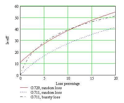
does it assume that the underlying network is re-     • GIPS - 13.3 kbps and up
liable. To help VoIP applications deal with un-       • GSM - 13 kbps (full rate), 20ms frame size
predictable network performance, the Real-time        • iLBC - 15kbps,20ms frame size: 13.3 kbps,
Transport Control Protocol (RTCP) is devel-             30ms frame size
oped to monitor the performance of RTP packets        • ITU G.711 - 64 kbps, sample-based. Also
and provide feedback to the VoIP applications.          known as A-law/µ-law PCM
The feedback on packet delay, jitter, and loss
                                                      • ITU G.722 - 48/56/64 kbps
rate enables the applications to adapt to net-
work conditions to maintain a certain level of        • ITU G.723.1 - 5.3/6.3 kbps, 30ms frame size
voice quality.                                        • ITU G.726 - 16/24/32/40 kbps
     In this report, we first look at the codecs      • ITU G.728 - 16 kbps
used in VoIP in Section 2. Codecs play an im-         • ITU G.729 - 8 kbps, 10ms frame size
portant role in determining the quality of a VoIP     • Speex - 2.15 to 44.2 kbps
call. In Section 3 we look at the various VoIP
                                                      • LPC10 - 2.5 kbps
quality measurement metrics. We describe how
                                                      • DoD CELP - 4.8 kbps
to measure the overall call quality in Section 4.
Having looked at the metrics, Section 5 describes
the experimentation methodology, followed by Figure 1: Most common VoIP codecs and their
the analysis of the experimental results in Sec- bitrates [4]
tion 6. Section 7 discusses what we achieved
from the project and in Section 8 we propose
possible future directions.                        VoIP have specific optimizations to encode hu-
                                                   man voice in a typical speech pattern. Encoding
                                                   is usually based on a fixed frame size. Larger
2 Codecs used in VoIP                              frames allow for more efficient encoding but in-
                                                   troduce larger delays and higher sensitivity to
CODEC is an acronym for COder/DECoder. A packet loss. Therefore the choice of a good frame
codec is responsible for converting a voice signal size is equally important as the choice of codec.
into a format suitable for transport and receipt Keep in mind that a codec’s bitrate is not equal
over a network. The codec at the sending end to the actual IP traffic, as typical VoIP packets
compresses (COdes) the voice signal for trans- are small and the IP and UDP headers impose
mission over the network. At the receiving end, a significant overhead. Figure 2 illustrates the
the codec decompresses (DECodes) the signal for overhead for common codecs.
the listener. Codecs vary in the sound quality,
the bandwidth required, the computational re-                Codec      Bitrate IP bitrate
quirements, etc. Each service, program, phone,                G.711    64 kbps 87.2 kbps
gateway, etc typically support several different              G.729     8 kbps 31.2 kbps
codecs, and when talking to each other, negoti-              G.723.1 6.4 kbps 21.9 kbps
ate which codec they will use.                               G.723.1 5.3 kbps 20.8 kbps
     The general requirement for VoIP codecs is               G.726    32 kbps 55.2 kbps
low bandwidth usage. As seen in Figure 1 a typ-               G.726    24 kbps 47.2 kbps
ical VoIP codec uses 10-30 kbps data rate. For                G.728    16 kbps 31.5 kbps
example, Skype’s iLBC [3] uses 13 kbps. An-                   iLBC     15 kbps 27.7 kbps
other important requirement is the ability to en-
code/decode in real time, which is not much of Figure 2: Actual IP bitrate used by various
an issue nowadays. Codecs specifically built for codecs [4]

                                                 2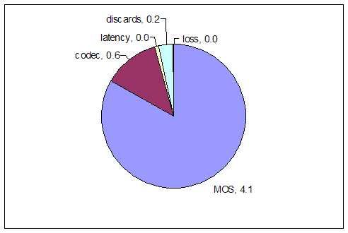
The presence of many different codecs (see           protocols have been developed. SIP[6], or the
Figure 1) showcases that there isn’t an obvi-             Session Initiation Protocol, is currently popular
ous choice, but variable network setups should            and used in many VoIP services. SIP is defined
be handled with different codecs or bitrates. A           in RFC 3261. The metrics for measuring the
valuable feature of many commercially available           signaling quality are given below. They refer to
VoIP products is the ability to switch bitrates           the time it takes to accomplish the various stages
while a conversation is in progress, delivering           of setting up a call. Assume A initiates the call
better quality on-the-fly.                                and the other end is B. There are 2 sets of met-
     Each codec provides a certain quality of             rics, one for each direction of the conversation.
speech. The quality of transmitted speech is              Basic knowledge of the SIP messages is assumed.
a subjective response of the listener. A com-
mon benchmark used to determine the quality of                From A to B:
sound produced by specific codecs is the Mean
Opinion Score (MOS) [5] .                                   • Post-Dial Delay is the time it takes, after
     One interesting point of research is alter-              A sends the INVITE message for the phone
native encoding codecs. By analyzing human                    at B to ring.
speech, it is concluded that speech can be syn-             • Call Setup Delay is the full time it takes
thesized using a relatively small (less than 8-10             after A sends the INVITE message for it to
taps) Infinite Impulse Response (IIR) vocal tract             receive the 200 OK response from B. Call
filter excited with either a quasi periodic impulse           setup delay includes post-dial delay.
train or white noise [12]. To transmit synthesized          • Media Delay includes the full call setup
speech through a network only the filter coeffi-              time plus the time it takes for B to re-
cients and a gain factor are transmitted. The                 ceive the first packet of media (conversa-
resulting data stream will require a bandwidth                tion). Media Delay includes both call setup
of 2.0 to 2.7 Kbit/s (assuming 8-bit IIR coeffi-              delay and post-dial delay.
cients). This provides a significant reduction in
required bandwidth compared to currently used                 From B to A:
VoIP protocols. However, implementing a voice
                                                            • Post-Pickup Delay is the time that
synthesizing codec to test the sound quality is
                                                              elapses between B sending the 200 OK re-
beyond the scope of this project.
                                                              sponse and receiving the first packet of me-
                                                              dia (conversation).
3    VoIP Quality Metrics                                   • Call Setup Delay is the time elapsed be-
                                                              tween the INVITE and the ACK messages
There are three important measures of VoIP                    that B receives from A. The ACK message
quality: (1)Signaling quality, (2)Delivery qual-              from A to B confirms that the call has been
ity, and (3)Call quality. In this section we                  successfully set up.
discuss how to measure each of them.                        • Media Delay is the time between receiv-
                                                              ing the initial INVITE request to receiving
    (1) Signaling Quality: It is a measure of                 the first media packet (conversation). Me-
the call setup performance. Before a conversa-                dia Delay includes both the call setup delay
tion can begin, a call must be setup. Both sides              and post-pickup delay.
need to be able to find and reach one another,
consent to talk, and agree how the call is to         (2) Delivery Quality : Once a call has suc-
proceed. Call setup is a complicated process. cessfully been setup, latency, jitter, and packet
Over the years, quite a few signaling (or setup) loss effects are important predictors of the call

                                                      3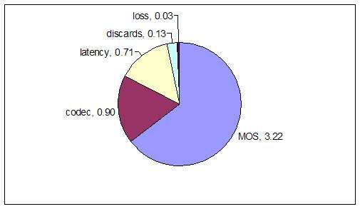
stream performance also called as the delivery                MOS    Quality       Listening Effort
quality.                                                       5    Excellent    Complete Relaxation
                                                               4      Good       Attention Necessary
  • Latency : A measure of the delay in a call.                3      Fair         Moderate Effort
    The largest contributor to latency is caused               2      Poor        Considerable Effort
    by network transmission delay. With round                  1      Bad       No Meaning Understood
    trip latencies above 350 ms users may expe-
    rience annoying talk-over effects.                        Figure 3: Understanding the MOS scores

  • Jitter : Jitter refers to how variable latency
    is in a network. High jitter, greater than            (MOS). The E-model and MOS are described in
    approximately 50 ms, can result in both               more detail in Section 4.
    increased latency and packet loss. Jitter
    causes packets to arrive at their destination         4    Measuring Speech Quality
    with different timing and possibly in a differ-
    ent order than they were sent (spoken), with          The fundamental concern for VoIP QoS is voice
    some arriving faster and some slower than             quality. Unfortunately, objective measurements
    they should. To correct the effects of jitter,        for this have been elusive. Modern communi-
    VoIP endpoints collect packets in a buffer            cations networks include elements (bad coding,
    and reorder them according to their tim-              error-prone channels and voice activity detec-
    ing and sequence number before the listener           tion) that cannot reliably be assessed by such
    hears them. This works, but it is a balanc-           conventional engineering metrics as signal-to-
    ing act. Processing that buffer adds delay to         noise ratio. One way to measure customers’
    the call, so the bigger the buffer, the longer        perception of the quality of these systems is to
    the delay. If voice packets arrive when the           conduct a subjective test involving panels of hu-
    buffer is full then packets are dropped and           man subjects. However, these tests are expensive
    the receiver will never hear them. These are          and unsuitable for such applications as real-time
    called discarded packets.                             monitoring. The Mean Opinion Score (MOS) is
  • Packet Loss : Some of the voice pack-                 a subjective number indicating how people feel
    ets may be dropped by network routers or              about the quality of the voice signal. MOS is
    switches that become congested, such pack-            measured on a scale from 1-5 where 1 is the low-
    ets are called lost packets. Knowing the av-          est and 5 the highest. Figure 3 shows the cor-
    erage packet loss rate for a call gives an            relation between MOS scores and the listening
    overall sense for the quality of the call. Ad-        quality.
    ditional information is needed to determine                In this project we use an online tool [8], to
    whether the loss was ’random’ or ’bursty’ to          measure the quality metrics described in Section
    infer the call quality.                               3. This tool uses the ITU G.107 E-Model. E-
                                                          Model produces an R-factor score which can be
     (3) Call Quality : The perceived quality             directly correlated to a MOS score. The R-value
of speech is highly subjective. However, sev-             is calculated as the sum of five variables:
eral methods for objective speech quality analy-         R = Ro − Is − Id − Ie−ef f + A,
sis exist. One example is the E-model [7], which
is an end-to-end model originally intended for       where Ro is the base signal-to-noise ratio
measuring speech quality of telephone networks. (SNR), Is represents the signal impairment in-
The result of an E-model calculation is an R- troduced simultaneously with the voice trans-
value which is related to the mean opinion score mission (e.g. quantization noise), I d is the im-

                                                      4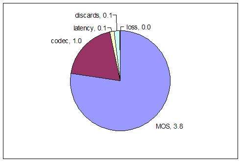
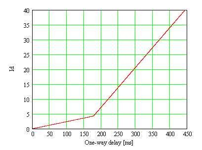
Figure 4: Relation between Id and delay               Figure 5: Relation between Ie−ef f and packet
                                                          loss percentage

pairment caused by delay (e.g. talker echo, lis-          in some cases even free service. Figure 6 shows
tener echo), Ie−ef f is the effective equipment           the network parameters which influence the R
degradation factor (e.g. codec loss), and A is an         factor. The user satisfaction as a function of R-
advantage factor. The relation between I d and            value and MOS is shown in Figure 7.
delay is shown in Figure 4 and Figure 5 shows
how Ie−ef f varies with the percentage of packets
lost.
      We see that once the one-way delay is in-
creased above 177 ms, the delay impairment on             Packet Loss     Loss Model

the speech quality is quite severe. For VoIP ap-
plications, this is actually a fairly stringent re-             Jitter    Jitter Model
                                                                                          Ie
quirement as IP traffic often experiences signif-                                              E Model   R Factor

icant delays as a result of network congestion,           Codec Type      Codec Model

link failures, and just general routing schemes.
Also note that the use of jitter buffers and the                         Delay Measured
                                                                         using RTCP
encoding itself introduces delay (10-25 ms is typ-
ical).                                                    Figure 6: Network factors which influence the R
      The advantage factor, A, is an attempt to           factor
quantify the user expectations for a particu-
lar communication medium. For example, cell
phone users may rate a certain quality level as
being of acceptable quality, whereas, for a land-
line telephone, the same level of quality would               While the theoretical MOS scale tops out
be rated as low quality solely because of user            at 5.0, practically speaking, a 5.0 score is not
expectations of the particular phone service. In          achievable regardless of the network connection
other words, cell phone users would be willing to         quality. That is because VoIP codecs intro-
trade some speech quality for the convenience of          duce some amount of quality loss. For example,
mobility. Similarly, VoIP users would likely be           the maximum MOS score achievable with G.711
willing to trade voice quality for a lower price -        codec is 4.4 and with G.729 codec is 4.2.

                                                      5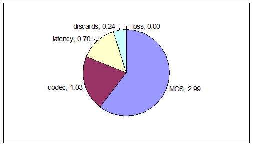
R-value (lower limit)   MOS (lower limit)               User satisfaction
                      90                   4.34                       Very satisfied.
                      80                   4.03                          Satisfied.
                      70                   3.60                   Some users dissatisfied.
                      60                   3.10                  Many users dissatisfied.
                      50                   2.58                 Nearly all users dissatisfied.

                   Figure 7: User satisfaction as a function of R-value and MOS

5    Experimentation Methodol-                           time, Media delay (6) Type of packet loss: Burst
     ogy                                                 or Random

The experiments were run over a period of two            6     Analysis of the Experimental
weeks and at various times of the day. A total
of about 600 experiments were run from Seat-                   Results
tle. No artificial load conditions (e.g background
                                                         In this section the results obtained from the ex-
downloads) were added to the network. The in-
                                                         periments are analyzed. Due to space constraints
tention was to test VoIP under normal load con-
                                                         not all the results are shown. In this report the
ditions. These experiments were equally divided
                                                         interesting results are plotted and other results
among four types of networks: (1) Dial-up from
                                                         are described in words. We mainly concentrate
home (2) 802.11 b/g wireless network at the UW
                                                         on the MOS from source to the target destina-
CSE department (3) Comcast Cable Network (4)
                                                         tion using G.711 codec. The results for the op-
UW CSE department switched gigabit ethernet
                                                         posite direction and using G.729 codec are sim-
network.
                                                         ilar. Recall that the maximum MOS that can
     In each of the networks above, calls were           be achieved with a G.711 codec is 4.4 and with
made to the following destinations: (1) Boston           a G.729 codec is 4.2. All results are averaged
(2) Helsinki (3) London (4) Montreal (5) San             over the number of experiments run with that
Jose (6) Sydney. Geographically San Jose, Mon-           setting. We concentrate on the delivery quality
treal and Boston as closer while Helsinki, London        (jitter, latency, packet loss and packet discards)
and Sydney are far off from the source location          and the call quality (MOS). Signaling quality is
i.e Seattle.                                             not very important as it is the characteristic of
     We tested two codecs which are popularly            the signaling protocol used (SIP) and does not
used in VoIP: (1) G.711 (PCM at 64 kbps, 20 ms           affect the speech quality . The graphs are all pie
RTP payload, 80 kbps IP bandwidth) (2) G.729             charts, to help the reader visualize the negative
(CS-ACELP at 8 kbps, 10 ms RTP payload, 40               contribution of each of the degradation factors
kbps IP bandwidth). G.729 trades off lower IP            (codec, latency, packet discards, packet loss) to
bandwidth for voice quality. It uses predictive          the ideal MOS score of 5.0.
coding and halves the IP bandwidth.
     The following parameters were obtained
                                                         6.1   Home Dialup Network
from each experiment (in both directions): (1)
MOS (2) Degradation due to the codec used, la-           One would expect that VoIP would not perform
tency, packet discards, and packet loss (3) Loss         well over dialup networks. On the contrary, VoIP
periods (4) Jitter (5) Signaling characteristics:        delivers a fairly good performance over dialup
Post-Dial delay, Post-Pickup delay, Call setup           networks. This can be attributed to the fact

                                                     6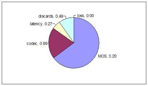
Figure 8: Overall MOS to any destination using         Figure 9: Overall MOS to any destination using
 G.711 over a dialup network                            G.729 over a dialup network

 Figure 10: MOS to San Jose using G.711 over            Figure 11: MOS to Helsinki Using G.711 over
 a dialup network                                       a dialup network

that VoIP codecs have a minimum bandwidth               Helsinki is mainly due to the latency, jitter (re-
requirement, which dialup networks can satisfy          sulting in discarded packets) and lost packets.
to a large extent. 24 kbps to 32 kbps is the av-        Our experiments rank the overall MOS (consid-
erage bandwidth provided by dialup networks.            ering both directions) to the destinations as San
The G.711 codec tested has a bandwidth require-         Jose > Sydney > Boston, London > Montreal >
ment of 80 kbps, while G.729 has 40 kbps re-            Helsinki. As we can see, geographical distance
quirement. If the entire bandwidth was avail-           plays a vital role in determining the end-to-end
able, these codecs would deliver their best per-        voice quality in dialup networks.
formance, i.e highest MOS. We see in Figures 8
and 9 that even though the bandwidth require-
ment is not satisfied, the MOS delivered by us-
                                                        6.2   802.11 b/g Wireless Network
ing the G.711 codec is 3.44 and by using G.729          The wireless network tested also performs fairly
is 3.22. Even more surprising is the fact the           well and is suitable for VoIP applications. The
quality degradation is due to discarded packets         average MOS to target locations using the G.711
rather than the lost packets. Hence a dialup net-       and G.729 codecs was 3.06 and 3.20 respectively.
work delivers all packets, but the packets do not       This is shown in Figures 12 and 13. The voice
arrive in time at the destination. Next, let us         quality using the G.729 is comparable to the
look at the individual destinations. The MOS            quality delivered by a dialup connection. The
to San Jose turns out to be the best, while it          quality of the G.711 codec is substantially lower.
is the worst to Helsinki. This can be seen in           In Figure 12 notice that the contribution of dis-
Figures 10 and 11. The degradation of MOS to            carded packets to degradation in voice quality is

                                                    7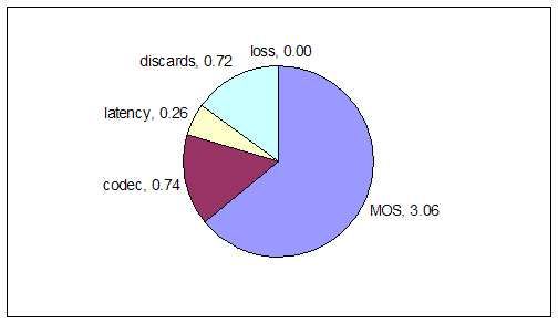
while the wireless network tested had a maxi-
                                                          mum capacity of 54 Mbps (802.11b/g). Hence
                                                          even though the minimum bandwidth require-
                                                          ments of the codecs are satisfied in a wireless
                                                          network, the jitter plays a vital role. The same
                                                          phenomenon is observed in experiments to each
                                                          of the target locations i.e packet discards are the
                                                          primary cause of voice quality degradation.

Figure 12: Overall MOS to any destination using 6.3             Cable Network
G.711 over a wireless network

                                                Figure 14: Overall MOS to any destination using
Figure 13: Overall MOS to any destination using G.711 over a cable network
G.729 over a wireless network

almost three times that of dialup and that la-
tency is almost half. The discarded packets are
due to the jitter experienced by the packets. The
maximum jitter observed by packets in the wire-
less network when using the G.711 codec was
observed to be 473 ms while it was just 129 ms
in the dialup network. We can conclude that
wireless networks are more prone to jitter result-
ing in discarded packets and consequently lower           Figure 15: Overall MOS to any destination using
voice quality. It is interesting to note that this        G.729 over a cable network
phenomenon is observed even when G.729 codec
is used. Hence, jitter experienced in wireless net-           Cable network delivers much better voice
works is not related to the throughput. Another           quality than dial up and wireless networks. This
possible reason for the large number of discarded         can be seen in Figures 14 and 15. The aver-
packets in wireless networks could be transmis-           age bandwidth available over a cable network is
sion errors (i.e collisions resulting in corrupted        approximately 3 Mbps (downlink) and 300 kbps
packets). The latency in a wireless network is            (uplink). The effects of latency, packet loss and
almost half that observed in a dialup network,            packet discards are almost negligible. The degra-
due to the difference in available bandwidths. A          dation in voice quality is only due to the codec
dialup network promises a maximum of 56 kbps              used. This is true for all target locations. The

                                                      8
Figure 18: Overall MOS to any destination using
Figure 16: Overall MOS from any destination G.729 over a gigabit ethernet network
using G.711 over a cable network
                                                        price of higher bandwidth requirements. The
most interesting result we found was, the up-           same graph is observed in experiments to every
link and downlink bandwidths do affect the voice        location. As expected, gigabit ethernet network
quality. The MOS to any destination was found           provides the best voice quality among all the net-
to be 4.1 using the G.711 codec while the MOS           works tested. This raises an important question
from any destination was 4.3. This is seen in           as to whether VoIP implementations can change
Figure 16. The improvement in quality is due to         the codec used according to the type of network.
the fewer number of discarded packets. Similar          We discuss this and some other possible future
results are observed by using the G.729 codec.          directions in Section 7.

6.4   Gigabit Ethernet Network
                                                        7    Discussion
                                                        From the analysis in the previous section we can
                                                        conclude that the available bandwidth is an im-
                                                        portant factor in determining the end to end
                                                        voice quality. We obtain the following ranking:
                                                        Dialup Network < 802.11 b/g Wireless Network
                                                        < Comcast Cable Network < Gigabit Ethernet.
                                                        It is interesting to note that even though in the
                                                        ideal case the maximum bandwidth provided by
                                                        a 802.11 b/g wireless network (54 Mbps) is much
Figure 17: Overall MOS to any destination using         more than that provided by a cable network (3
G.711 over a gigabit ethernet network                   Mbps/300 kbps), cable networks deliver much
                                                        better voice quality. This is primarily caused
    A gigabit ethernet network easily satisfies         by collisions or transmission errors on the wire-
the minimum bandwidth requirements of the               less network reducing the effective bandwidth,
codecs under test. This is seen in Figures 17           however, the fact that the total bandwidth is
and 18. The degradation due to latency, packet          shared amongst several users is also a significant
discards and packet loss are negligible. The only       contributing factor. Figures 19 and 20 show a
degradation is due to the codec used. This is           sample traceroute analysis of voice packets from
inevitable, and can be overcome only by using           London to Seattle. Figure 19 corresponds to a
codecs which provide better voice quality at the        home dialup connection with AOL as the ISP,

                                                    9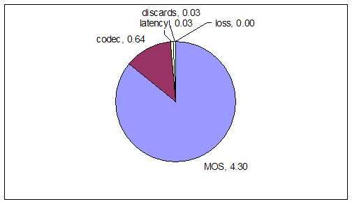
Figure 19: Traceroute analysis over a dialup net-     Figure 20: Traceroute analysis over a gigabit eth-
 work                                                  ernet network

while Figure 20 shows the analysis for a connec-     it must support different modes (frame size, bit
tion over the CSE department gigabit ethernet        rate, etc.) The AMR speech codec presented in
network. The most striking feature of this anal-     [11] is an example of such an adaptive codec.
ysis is that the delay over a dialup connection is   This codec allows for the encoding bit rate to be
more than double the delay over a gigabit eth-       changed adaptively in eight discrete steps within
ernet network, the main culprit being the delay      the range of 4.75 kbit/s to 12.2 kbit/s. The best
from the ISP to the end host which is almost         obtainable MOS range from 3.0 at the lowest bit
the same as the intercontinental delay. It is this   rate to 3.5 at the highest. As shown in Section 6,
delay at the edge of the network that degrades       this is roughly equivalent to the performance of
VoIP quality in dialup networks.                     the G.711 and G.729 codecs when used over a di-
                                                     alup network. However, by using the AMR codec
                                                     at its lowest bit rate, the network bandwidth re-
8     Future Directions                              quirement is reduced by approximately 40 %. In
Motivated by our findings we now propose pos-        addition, the AMR codec has higher packet loss
sible future directions that address the most sig-   tolerance than any of the aforementioned codecs,
nificant degradation factors.                        which for use on lossy networks would be an ad-
                                                     vantage. This, combined with the lower band-
                                                     width requirement, would make it possible to
8.1   Adaptive VoIP Clients                          achieve reliable VoIP service on slow networks
We have seen in Section 6 that voice quality de-     like dialup connections. However, if the AMR
pends on a number of factors. Depending on           codec is to be significantly better than G.729,
the bandwidth available and the type of network,     its equipment impairment factor, I e , will need to
the effect of these factors varies. If the network   be lowered while maintaining its high packet loss
conditions are known prior to establishing the       tolerance.
VoIP call, an appropriate codec can be chosen
in order to achieve the best possible voice qual-    8.2   QoS Guarantees by the Client
ity for the given network conditions. However,             Side OS
to provide the best possible speech quality as
network conditions change over time, the codec       We have seen that commercial VoIP clients have
must be adaptive; i.e., either the codec must be     very low bandwidth requirements typically in the
swapped out entirely for a different codec, or       range of 10-30 kbps. A major fraction of this re-

                                                 10
quirement is satisfied even on dialup networks. the time sensitive nature of voice traffic, the re-
With the emergence of new codecs like iLBC transmission of damaged, delayed or lost pack-
which has a requirement of only 13 kbps, band- ets is not feasible as a technique for correcting
width would no longer be a constraint. However, packet transmission errors. A forward error cor-
during our experimentation we observed that rection algorithm which offers improved voice re-
background downloads affect the speech quality liability at the cost of minimum additional delay
severely, especially on slow connections like di- or bandwidth would be the ideal solution to this
alup networks. This is because the background problem. The main idea is to transmit redun-
download process utilizes almost the entire avail- dant packets that will allow the receiver to re-
able bandwidth (assuming data is available at construct the voice data even when a small frac-
that rate) and the VoIP client does not receive tion of packets are lost. Forward error correction
its minimum required share. But even on cable on VoIP has been studied in research extensively
connections, the jitter introduced by other traf- and shows a lot of promise in delivering stronger
fic impacts the voice quality. This motivated us QoS guarantees [9, 10].
to look for QoS guarantees from the local op- Most of the forward error correction schemes
erating system. The local OS can prioritize the use well established codes, such as Reed-Solomon
bandwidth allocation among the contending pro- codes. In order to generate the redundant pack-
cesses. This can be done in two straightforward ets, one has to sacrifice a fraction of the actual
ways: audio data in effect limiting the optimal quality
achieved. However, when packets drop or packet
1. Allocation of a minimum amount of band- loss occurs, the receiver is still able to recon-
width for applications struct the audio data, yielding a much better
MOS score on average.
2. Giving higher bandwidth priority to time
sensitive applications Different code rates need to be chosen to deal
with different packet loss ratios. The code rate
A combination of these methods can also be affects the perceived audio quality as it limits
used. Since an application running in user mode the actual audio data transmitted over a fixed
cannot modify the bandwidth reservation policy bandwidth. Therefore, a careful selection of the
of the kernel, these changes have to incorporated code rate needs to be done based on the packet
into the kernel. It turns out that it is fairly easy loss ratio. However, the packet loss ratio is gen-
to modify the kernel to allow for such require- erally not known in advance and may vary over
ments. To our knowledge this extension to VoIP time. This naturally leads to the proposal of
has not been studied previously. We strongly be- forward error correction schemes with adaptive
lieve that incorporating QoS guarantees by the rate. Most of the research done in the field sug-
client side OS would boost the user satisfaction gests a feedback mechanism that monitors the
especially on slow networks. Moreover, such ex- packet loss ratio and adjusts the code rate ac-
tensions to the kernel would help the entire range cordingly to compensate.
of time sensitive applications, which would soon Unfortunately, this approach has not been
be widely used. implemented by VoIP providers mainly due to
the computational overhead involved in real-time
8.3 Error Correction encoding, the additional bandwidth require-
ments, and larger buffer space needed. However,
VoIP sends voice packets over UDP. Packets there are some commercial patents pending in
may be lost or discarded due to transmission er- this field. Our best guess is that such systems
rors, delays, network congestion, etc. Due to will become available in the following years.
119 Conclusion asp?type=items&lang=e&parent=T-RE%
C-G.107-200303-I.
In this project our goal was not to evaluate the
performance of various VoIP implementations [8] http://www.testyourvoip.com.
but investigate the limitations of the technol-
[9] Yvan Calas and Alain Jean-Marie. Audio
ogy itself. It is well known that the way the
quality for a simple forward error correction
Internet has evolved over the years, it has not
code under bursty traffic conditions. Inter-
evolved into the ideal environment for QoS ser-
national Conference on Communications in
vices. A major open question we faced when we
Computing (CIC 2004).
started working on the project was whether we
can ever achieve satisfactory VoIP services us- [10] Wenyu Jiang and Henning Schulzrinne.
ing the present Internet framework. We listed Comparison and optimization of packet loss
five basic questions at the beginning of the re- repair methods on voip perceived quality
port. We felt that these are questions anyone under bursty loss. Proceedings of the 12th
interested in VoIP research would face. These international workshop on Network and op-
questions directed our approach during various erating systems support for digital audio and
stages of the project. We feel that we have been video, 2002.
able to answer these questions to the best pos-
sible extent. We hope that the analysis of VoIP [11] J. Matta, C. Pepin, K. Lashkary, and
presented in this report would help in deeper un- R. Jain. A source and channel rate adap-
derstanding of the technology and fuel future re- tation algorithm for amp in voip using the
search in the field. e-model. NOSSDAV, 2003.
[12] Oppenheim and Shafer. Discrete-Time Sig-
References nal Processing. Prentice-Hall, 1999.
[1] AT&T http://www.att.com/voip/.
[2] Vonage http://www.vonage.com.
[3] ILBC codec. http://www.globalipsound.
com/pdf/gips_iLBC.pdf.
[4] http://www.voip-info.org.
[5] Mean Opinion Score (MOS) ter-
minology. http://www.itu.int/
rec/recommendation.asp?type=
folders&lang=e&parent=T-%REC-P.
800.1.
[6] Session Initiation Protocol (SIP)
http://www.ietf.org/html.charters/
sip-charter.html.
[7] The E-Model, a computational model
for use in transmission planning http:
//www.itu.int/rec/recommendation.
12You can also read