PETROLEUM HYDROCARBON CONTAMINATION INCIDENT AT CHRISTCHURCH CITY COUNCIL GROUNDWATER PUMPING STATION
←
→
Page content transcription
If your browser does not render page correctly, please read the page content below
PETROLEUM HYDROCARBON
CONTAMINATION INCIDENT AT
CHRISTCHURCH CITY COUNCIL
GROUNDWATER PUMPING STATION
G. Knoyle; Pattle Delamore Partners Ltd
A. Beard, B. Henderson; Christchurch City Council

ABSTRACT
In March 2003 dissolved petroleum residues were noted by the general public within the Christchurch City
Council’s reticulated drinking water supply.

Initial investigations at the closest operating pumping station showed that the source of the petroleum residues
had to have originated from either a leaking underground fuel supply line or from broken stormwater pipes that
inadvertently received petroleum residues from cleaning activities within the pumping station.

Petroleum residues were noted floating on water present within the base of the well head chamber of one of the
shallow supply wells. Petroleum residues had not contaminated the aquifer utilised by the well, but had entered
the well via a faulty flange joint at the base of the well head chamber.

Excavations around the affected well head chamber and underground fuel line coupled with the installation of
five monitoring wells indicated the presence of petroleum residues around the foundations of the pump house. A
product recovery well was installed and around 35 L of fuel recovered.

All seals between the affected well and pumping station have been replaced and the system disinfected.
Groundwater monitoring of the supply wells and monitoring wells following removal of the contaminant sources
has shown attenuation of petroleum residues to non-detectable levels and as such the site has been
recommissioned nine months after the initial contamination.

KEYWORDS
Groundwater contamination, petroleum hydrocarbons, reticulated water supply.

1     INTRODUCTION
The urban area of Christchurch is supplied by a reticulated drinking water supply under the management and
control of the Christchurch City Council (CCC). The water supply is sourced from groundwater obtained from a
series of gravel aquifers, which lie beneath the city.

At times, for cost efficiency the CCC use on-site diesel run generators to power pumps that abstract groundwater
from the underlying aquifers to supply the surrounding residential and commercial/industrial areas. As such,
diesel fuel is typically stored in either aboveground or underground tanks. Due to the size constraints of some of
the CCC pumping station sites the fuel storage is located in close proximity to the abstraction wells. Under these
circumstances the possibility exists for contaminants, such as diesel fuel, to inadvertently enter the reticulated
water supplies as a result of equipment failure or improper on-site maintenance and/or management procedures.

This paper describes such an incident whereby diesel fuel inadvertently entered the CCC reticulated drinking
water supply system at one of their pumping stations within the north-west Christchurch catchment. The paper
sets out the investigation procedures that occurred following notification by the general public of tainting of the
water supply. These procedures included excavation and removal of contaminated soil, installation and
sampling of groundwater monitoring wells, sub-surface diesel recovery and improvements to the pumping
station pipework and maintenance/management procedures.
2 SITE LAYOUT
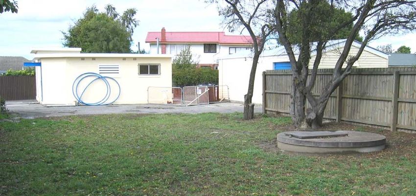
The CCC operated Auburn Ave pumping station is located on a rear section on the southern side of Auburn Ave
in the western residential suburb of Riccarton, Christchurch. The site is bounded by residential properties on the
northern, eastern and western boundaries and by Middleton Grange School playing fields to the south. The site,
which is flat, comprises two buildings. A block building is centrally located along the eastern boundary and
houses the pumping station and a garage/utility storage building is located along the southern boundary. The
concrete floor of the pumping station is approximately 2.7 m below ground level.
The site surface comprises an asphalt sealed access-way from Auburn Ave whilst the southern and western areas
are grassed. An underground concrete lined suction/storage tank (approximate dimensions of 7 m diameter and
7 m depth) is located immediately to the west of the pumping station beneath asphalt seal and is recharged by
two flowing artesian wells (Well No. 2 and Well No. 3). Two concrete well head chambers, housing supply
wells, are also located at the site, one on a grassed area to the south of the pumping station (Well No. 4) and the
second on a grassed area to the west of the pumping station and suction tank (Well No. 5). Well No 5 also
supplies the suction tank via a modulating valve to control levels within the tank. The four wells contribute to
the CCC’s reticulated water supply system in the area.
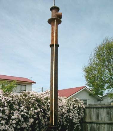
Photograph 1: Auburn Ave Pumping Station (viewed looking east)
Area of Diesel Leak
Pumping Station
Suction Tank Location
Well No. 5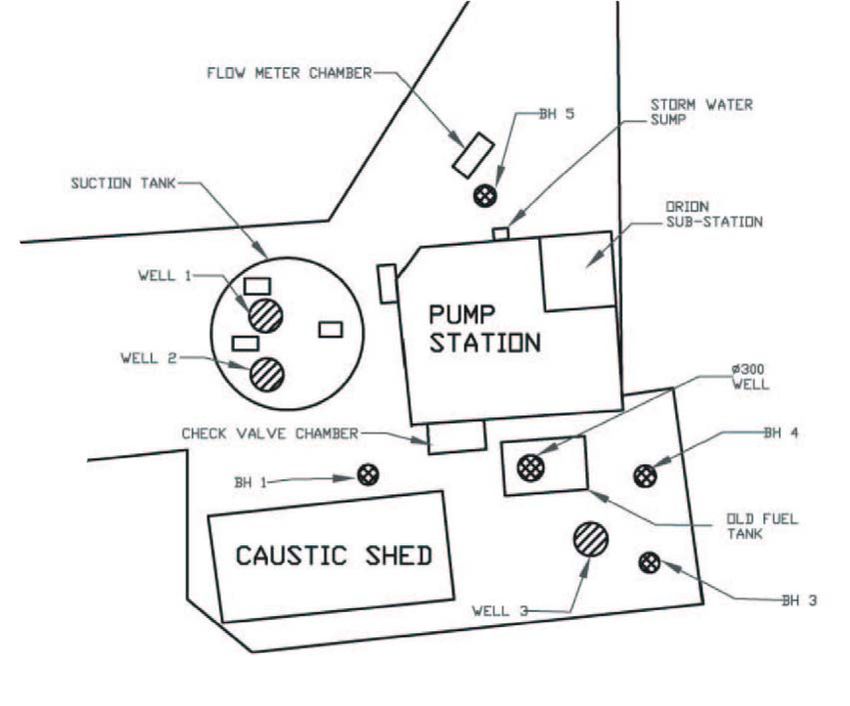
Figure 1:       Plan view of Auburn Ave Pumping Station

                                                                            BH5

                                          Well No 2

                  Well No 5
                                          Well No 3

                                                                                                    BH4

                                                             BH2
                               BH1

                                                                                                    BH3
                                                                              Well No 4

3     DESCRIPTION OF SUBSURFACE                                     SOIL,         HYDROLOGY                AND
       GROUNDWATER USE
The geological map of the Christchurch Urban Area (Brown & Weeber, 1992) shows that soils underlying the
site comprise mainly of fine grained alluvial sand and silt deposits. This is confirmed by the logs from the on-
site shallow monitoring wells, the logs of the four on-site public supply wells and from two wells located up to
350 m north of the site. The borehole logs have been obtained from Environment Canterbury’s (ECan) well
database.

The on-site monitoring well logs show low permeability silts and silty sands extending to depths of at least 8.5 m
below ground level within the deepest monitoring borehole (BH1). The ECan logs of the four on-site public
supply wells also show the underlying soils to comprise low permeability strata to depths of between 10 and
11.9 m below ground level. A summary of the well depth and screen data for the CCC supply wells is shown
below:

                                 Site Plan            Screen Set
                                 Reference            Depth (m)

                                 Well No. 2           19.5 - 27.1

                                 Well No. 3           27.1 - 33.2

                                 Well No. 4           29.2

                                 Well No. 5           166-172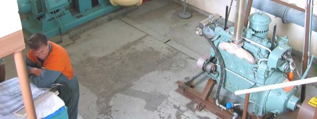
The strata logs of the two wells located between 85 m and 350 m north-west and north of the site, respectively,
also show low permeability soils to depths of between 10 m and 17.6 m below ground level. The logs of the
deeper wells generally show that the near surface low permeability soils are underlain by a sequence of gravel
aquifers interspersed by lower permeability layers to depths of up to 190 m below ground level.

Based on the Christchurch Artesian Aquifers Report (North Canterbury Catchment Board, 1986) the low
permeability, fine grained silty and sandy soils in the wider area are expected to extend to depths of around 16 m
below ground level, beneath which are a series of gravel aquifers separated by fine grained layers. The first
aquifer extends between 16 m to 40 m below ground level and has water pressures ranging between 2 and 9 m
below ground level, whereas the second aquifer extends between 62 and 82 m below ground level and has water
pressures ranging between 3 and 6 m below ground level. These aquifers form part of the Christchurch Artesian
Aquifer System.

Groundwater has been observed in the on-site monitoring wells (BH1 to BH5), on 6 May 2003, at depths ranging
between 2.144 m (BH3) to 2.635 m (BH1) below ground level. The water levels measured within BH1 to BH5
indicate quite variable groundwater elevations. It is likely that the presence of the large suction tank, the deep
foundations of the pumping station and the variable permeability of soils within the backfilled excavation are
influencing the local groundwater levels at these shallow monitoring wells. Within the underlying gravel
aquifer, larger scale piezometric surveys throughout the city indicate a south-easterly direction of groundwater
flow.

New Zealand guidelines have been developed that define whether the underlying aquifer is sensitive with respect
to its potential use as a potable supply (Ministry for the Environment, 1999). Based on the geological profile of
the soils beneath the site and within the surrounding area the underlying aquifer is not considered to be sensitive.
The low permeability soils which underlie the site and surrounding area form part of the surface confining layer
for the Christchurch confined aquifer system. In this area the shallow water table noted in the monitoring wells
at the site is unlikely to be used for a potable supply. The site and surrounding properties are serviced by the
Christchurch City Council’s reticulated water supply sourced from groundwater wells abstracting water at not
less than 19.5 m below ground level.

The nearest surface waterway is the Avon River, located approximately 1,000 m north-east of the site, which
flows in a general easterly direction.

4       THE CONTAMINATION INCIDENT
4.1      INITIAL OBSERVATIONS
A resident of the north-west Christchurch suburb of Ilam was the first to note petroleum tainting of their
reticulated water supply in the evening of 7 March 2003. The pumping station and the property that first
reported the tainting is separated by approximately 1 km of reticulated pipework.

As an immediate consequence, that evening, CCC representatives inspected seven pumping stations within the
north-west Christchurch reticulated catchment, which had on site petroleum hydrocarbon storage (typically
diesel for the backup generator), to check for any obvious fuel losses. An additional five pumping stations
within the catchment were also checked on the morning of 8 March. Nothing obvious was noted during the
initial investigations, however, as a prudent approach Auburn Ave pumping station, which was the only
operating station within the area at that time, was shut down at 10pm, 7 March. A total of 12 complaints
regarding the quality of the reticulated water supply were recorded on the evening of 7 March.

4.2      INITIAL SITE INSPECTION
4.2.1    DETECTION OF PETROLEUM RESIDUES WITHIN WELL NO. 4
An inspection by CCC representatives at the Auburn Ave pumping station on 10 March revealed the presence of
separate phase diesel with a thickness of up to 0.3 m floating on water within a check valve chamber, located on
the south-western corner of the pumping station.

In addition, petroleum staining was noted on the walls of the concrete well head chamber of Well No. 4 to a
height of around 0.3 m above the chamber base and a thin layer of diesel was noted floating on water present at
the base. The base of the well head chamber of Well No. 4 is around 2.6 m below the surrounding ground level.
The well utilises a surface pump which is located within the pumping station. The well has a dip pipe
(approximately 4 m long down the well casing) that has a foot valve located at its base. The CCC collected a
sample of water from the dip pipe via an access port on the top of the well head and they reported that no
obvious visual or odorous petroleum content was present. However, following the removal of the dip pipe from
the well an oily film was noted within the annular space between the dip pipe and the well casing.
It is worth noting that Environment Canterbury, the Regional Council, had previously inspected this well head in
November 2002, as part of a routine sampling programme, and no petroleum hydrocarbons were reportedly
present. Therefore, it is assumed that the petroleum hydrocarbons entered the well head chamber after this point
in time.
The CCC reported that further inspection of the flange joints between the dip pipe and the well casing at the base
of Well No. 4 chamber revealed that a plastic sampling pipe was pinched between the flanges, thus preventing a
water tight seal. According to the CCC the condition of the gasket between the two flange joints suggested that
it was not able to provide an effective seal.
Figure 2: Schematic Diagram of Well No. 4
Well Chamber
Hatch
Well Chamber
Ground Level Hatch
Ground Level
0.7 m
WellWell Head
Head Chamber
Chamber
2.6 m
2.6 m
Suction Pipe
Suction Pipe
Dip Pipe
Dip Pipe
4.0 m
Well Well Casing
Casing
Water
Water Level
L l
Foot Valve
Foot Valve
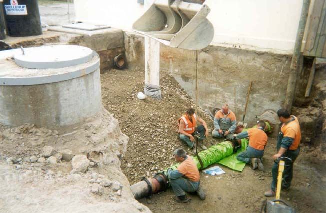
4.2.2 EXCAVATION WORKS AT PUMPING STATION
An excavation was undertaken by CCC representatives at the rear of the pumping station and adjacent to the
site’s 2,250 L aboveground fuel storage tank (AST) containing diesel on 11 March 2003. During the excavation
works the fuel line from the AST was exposed and diesel was noted seeping from the line, although the sand
immediately surrounding the AST had no obvious petroleum odour. The tank and associated pipework were
removed from the site.
The excavation extended between the rear of the pump building, the check valve chamber and Well No. 4.
During the excavation works, under the supervision of PDP, petroleum affected soils were noted up to a depth of
around 3 m below ground level. The suction pipe between Well No. 4 and the pumping station was exposed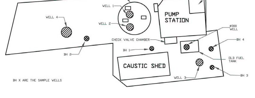
with the invert depth of the pipe occurring at around 2.2 m below ground level (diameter 250 mm). The soils
surrounding the pipe had a petroleum odour.

Black, degraded fuel was noted seeping from the base of the building foundations, at around 3 m depth, at the
rear of the pumping station and into the base of the excavation. All petroleum affected soils from the excavation
were carted to a Christchurch remediation facility. However, as indicated by the degraded fuel observed seeping
from beneath the pumping station, petroleum hydrocarbon affected soils remain beneath the site, under the
building foundations.

                             Photograph 2: Excavation to Rear of Pumping Station

                                                                                                  Pumping
   Check Valve
                                                                                                  Station
         Sump

                                                                                                  Pumping
                                                                                                  Sump

     Well No. 4
      Chamber

                                                                                                  Suction Line

A small submersible pump was placed into the base of the excavation and the fuel/groundwater mixture was
removed into three 1,000 L tanks, which were interconnected with submerged outlets to operate as a simple
oil/water separator. The discharge from the third tank entered the site’s reticulated stormwater system. No
obvious sheening or odour was noted on the discharge water entering the stormwater system, indicating that the
oil-water separator was operating successfully. During a site inspection undertaken on 2 April 2003 a layer of
black product with a thickness of around 30 mm was present within the first 1,000 L tank of the oil separator
system. The product had an odour similar to that of diesel.

A sample of the product present within the first 1,000 L tank of the oil separator system (sample ref. ‘IC1’) was
collected into a laboratory bottle for subsequent identification.

4.2.3    PUMPING SUMP INSTALLATION
Following the removal of petroleum affected soils from within the excavation to the rear of the pumping station
a 400 mm diameter PVC pipe with overlapping diagonally cut slots was installed to a depth of around 3.9 m
below ground level. The immediate area surrounding the slotted section of the pipe was backfilled with clean
gravels which were underlain and overlain by filter cloth, whilst the remaining excavation was backfilled with
sandy gravels.

It should be noted that as a prudent measure all seals along the suction pipe joints were replaced before the pipe
was reconnected and the excavation backfilled.

The small submersible pump was placed into the base of the PVC casing and the pumped fuel/groundwater
mixture was discharged into the three stage plastic tanks, prior to being disposed of into the reticulated
stormwater system. Regular inspection of the discharge into the stormwater system showed no obvious signs of
petroleum hydrocarbon residues or odour. A pumping discharge rate of approximately 0.015 L/s was required to
hold the water level at the base of the sump (a drawdown of the original groundwater table of around 1.9 m). In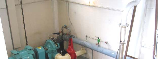
addition, regular inspections of the three 1,000 L separation tanks were undertaken to check for the accumulation
of separate phase product.

4.2.4    PETROLEUM HYDROCARBONS PRESENT WITHIN PUMPING STATION
Clear separate phase product with a thickness of around 20 mm was observed within a small concrete sump
located within the north-western corner of the pumping station. The CCC surmised that the source of the
product might have been as a result recent maintenance and cleaning of a diesel engine within the building. A
sample of the product (sample ref. ‘Pump House Sump’) was collected into a sample bottle for laboratory
identification.

Any water that collects in the sump within the station gets pumped to a ground level sump at the front of the
building and then is discharged to the reticulated stormwater system. The fuel noted in this station sump had
been inadvertently pumped to the reticulated stormwater system, although it was not known over what time
frame this had occurred. During the investigation works by CCC it was found that the stormwater pipes adjacent
to the ground level sump were broken thus providing a route for hydrocarbon migration towards the water table.

                                    Photograph 3: Inside Pumping Station

      Well No. 4
     Suction Line

                                                                                                Cable and
                                                                                                Pipe Conduit

   Concrete Floor

                                                                                                Diesel
                                                                                                Generator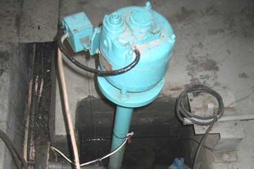
Photograph 4: Sump Inside Pumping Station

                                                                                  Electric Pump
              Cable and Pipe
                     Conduit

                                                                                  Concrete Sump

                                                                                   Discharge Pipe to
                                                                                   Surface Stormwater
                                                                                   Sump

4.3      LIKELY FUEL MIGRATION PATHWAY INTO WELL NO. 4
According to the CCC the demand on Well No. 4 was reasonably high on Friday 7 March. The well was being
pumped between 5:41am to 8:40pm on 7 March and contributed around 4,000 m3 of a total 30,000 m3 supply
within the north-west catchment zone that day. A plausible scenario is that fuel had entered the Well No. 4 well
head chamber, through cracks, etc, and was floating on water at the chamber base. The trench for the suction
pipe from Well No. 4 to the pump station building could have provided a permeable pathway for the migration
of petroleum hydrocarbons. The fuel/water mix was able to enter the well casing via the faulty flange joint at the
chamber base and floated on the water surface in the annular space between the well casing and the dip pipe.
Due to the heavy demand on the pumped well on 7 March the water table within the well was drawn down to a
depth where dissolved petroleum hydrocarbons associated with the floating petroleum hydrocarbons could enter
the dip pipe and thus petroleum affected groundwater entered the reticulated system.

5      GROUNDWATER MONITORING WELL INSTALLATION
PDP supervised the drilling of five groundwater monitoring boreholes at the pumping station between 24 and 25
March (BH1 to BH3) and 2 and 3 May 2003 (BH4 and BH5). The wells were installed to further define the
lateral extent and hence impact of the petroleum residues released into the surrounding ground. The locations of
the installed groundwater monitoring wells are shown in Figure 1.

Each borehole was drilled to depths of between 5.5 m (BH4) and 8.5 m (BH1) below ground level to intercept
the groundwater table at times of low water levels. Drilling was carried out utilising a truck mounted
compressed air driven ”Concentrix” ‘down-hole-hammer’ drilling rig. Each standpipe comprised a 50 mm
diameter slotted uPVC pipe and screened between the base of each borehole installation and to a depth of up to
0.4 m below ground level (BH4). A plug of bentonite clay was installed above the screen packing material to
prevent the inflow of stormwater. The surface of each borehole installation was finished with concrete and a
lockable toby box set flush with the ground surface.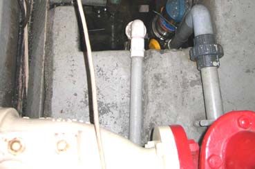
6     GROUNDWATER MONITORING WELL AND RETICULATED SUPPLY
      SAMPLING
6.1      SAMPLING PROGRAMME
Sampling of the on-site monitoring wells and/or of specific sections of the CCC’s reticulated water supply (e.g.
suction tank, Well No. 4 and reticulated piping) has been conducted on five separate occasions between 2 April
and 26 November 2003.

The requirement for sampling was to ensure that the petroleum residues were reducing in concentration and to
confirm that the water supply was safe to use again before recommissioning.

6.2      MONITORING WELL SAMPLING
With regard to the groundwater monitoring well sampling rounds undertaken on 2 April and 6 May 2003 the
same sampling methodology was carried out. On each occasion prior to sample collection, the depth to the water
table below the rim of each monitoring well was measured, and the presence of separate phase product was
checked using a clear plastic bailer to cut the surface of the water within each well casing. The wells were
purged of at least three times the volume of water standing in the casing to ensure that representative
groundwater that had not been exposed to the open environment was sampled. The water samples were collected
using one-litre capacity dedicated bailers.

6.3      WELL NO. 4 SAMPLING
A groundwater sample was collected from the CCC decommissioned Well No. 4 on 2 April 2003. Due to the
well specifications and with the pump having been disconnected it was not feasible to purge the well of the
equivalent of three well casings and as such a sample was collected directly from the dip pipe using a plastic
one-litre dedicated bailer.

6.4      SUCTION TANK SAMPLING
A sample of the groundwater that was present within the suction tank was collected on 16 May 2003. The
sample was collected directly from the tank via the ground level manhole and using a plastic dedicated bailer.

6.5      MAIN DISCHARGE PUMP AND FIRE HYDRANT SAMPLING
The suction tank was emptied to the Auburn Ave kerbside between 17 and 19 July 2003 using a submersible
pump and direct aboveground hosing. During this time, water level measurements were taken in the suction tank
and at on-site monitoring wells to determine if the shallow water table outside the tank was affected by the drop
in water level inside the tank. The water levels in the monitoring wells remained relatively constant as the water
level in the tank dropped from around 2 m to 7 m below ground level. This suggests that the suction tank is not
receiving contaminated groundwater from the surrounding shallow water table.

Whilst empty, the inside of the suction tank was cleaned with a high pressure hose and approximately 1 m3 of
sand that had entered the tank via Wells No. 2 and No. 3 was removed. Once the suction tank naturally refilled
the water was chlorinated and allowed to stand for three hours before flushing of the reticulated system attached
to the suction tank began.

To confirm the absence of petroleum residues in the suction tank and reticulated pumping system at the Auburn
Ave station, water samples were collected on 22 July 2003 from the main pump and from the fire hydrant
located approximately 30 m west of the Auburn Ave pumping station driveway. A sample was collected from
the fire hydrant to provide a representative sample of the water in the reticulated water supply being pumped
from Auburn Ave pumping station. Prior to collecting the samples the pump had been operating for
approximately four hours with two fire hydrants in Auburn Ave being used to draw the water from the
reticulated system. The sample from the main pump was collected from the sampling tap at the side of the
pump. The second sample was collected directly from the fire hydrant hose.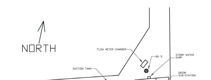
6.6      DISCHARGE PUMP FOLLOWING ISOLATION OF WELL NO. 4
During September, October and November 2003 the CCC undertook clean-up works of the affected Well No. 4
so that it could be brought back into service. The flange joint at the base of the well casing was cleaned and new
seals fitted. The dip pipe and well head casing were cleaned with a steam cleaner. Following the reinstallation
of the dip pipe the well and the suction line between the well head and pump station were chlorinated.
Following a 24 hour period of chlorination a lay flat hose was connected to the recently installed pipework that
allowed isolation of the groundwater abstracted from Well No. 4 following pumping.

                       Photograph 5: Reinstallation of Dip Pipe into Well No. 4 Casing

                                                                                  Suction Line
                                                                                  Connection
              PVC Sampling Port

Groundwater was pumped from the well in isolation from the remaining station’s water supply wells at a rate of
approximately 80 L/s for a period of one hour before representative groundwater samples were collected. The
depth to groundwater within the five monitoring wells (BH1-BH5) was measured at around 30 minutes
following start up of the discharge pump and following around 60 minutes following start up. Following 30
minutes of pumping at around 80 L/s the depth to water within the monitoring wells increased between 11 mm
(BH3) and 71 mm (BH2). No change in water level was measured in BH1, located furthest from Well No. 4.

6.7      SAMPLE HANDLING, STORAGE AND ANALYSIS REQUEST
On each occasion groundwater samples were collected into glass bottles supplied by the analytical laboratory.
Following collection, all samples were stored in a chilly bin containing frozen ice packs before being transported
via an express courier to RJ Hill Laboratories Ltd in Hamilton. The groundwater samples from the four separate
sampling rounds were received the following day after collection.

All water samples were analysed for total petroleum hydrocarbons (TPH), benzene related compounds (BTEX)
and poly-cyclic aromatic hydrocarbons (PAH). TPH analysis provides a general indicator of the level of
petroleum contamination by a broad range of compounds within the sample. BTEX compounds only constitute a
small percentage of the 500 or so different compounds present within diesel. For example, benzene only
constitutes around 0.5% by weight of diesel fuel. However, BTEX compounds, and in particular benzene, are
the most soluble of the petroleum hydrocarbons and hence the most mobile within a groundwater environment.
In addition, benzene is a limiting carcinogenic compound with respect to the protection of human health. PAH
compounds are typical of the more heavy fuels including diesel. They are less soluble than BTEX compounds,
however, certain compounds (benzo[a]pyrene) are carcinogenic to humans.
7 GROUNDWATER SAMPLING RESULTS 7.1 SAMPLING UNDERTAKEN ON 2 APRIL 2003 At the time of sampling on 2 April 2003 three monitoring wells had been installed (BH1-BH3). No obvious petroleum hydrocarbon odour or sheening was noted on the water surface within the three monitoring wells (BH1 - BH3) prior to or during the purging process. With respect to Well No. 4 clear globules and a petroleum hydrocarbon sheen were noted on the water surface within the well standpipe casing. The groundwater sampling results have been summarised below: Well TPH Benzene Toluene Ethyl Total Benzo[a]pyrene Naphthalene Pyrene Ref Benzene Xylenes BH1
7.3        SAMPLING UNDERTAKEN ON 16 MAY 2003 – SUCTION TANK
 TPH        Benzene      Toluene       Ethyl        Total        Benzo[a]pyrene   Naphthalene   Pyrene
                                       Benzene      Xylenes
2) to remove mobile separate phase product and dissolved phase product that was present within the
immediate vicinity of the pumping zone.
Several days prior to commencing the test the small submersible pump within the pumping sump was switched
off so that the groundwater level within the immediate vicinity could recover to a static level. The three 1,000 L
separator tanks were emptied and the contents disposed of at a suitable facility. In addition, the preceding three
days to the start of the pumping test and throughout the pumping test were dry with no rainfall occurring in the
local area.
In the hour prior to the start of the test the static water level was measured up to five times using an electronic
water level probe at the respective monitoring points. Immediately after the test had started water level
measurements were collected from the pumping sump, the five monitoring wells, Well No. 4 and the suction
tank as quickly as possible (every few minutes) to get as many measurements of the initial drawdown response.
Once the pump had been running for approximately one hour the water level measuring frequency reduced to
between 5 and 10 minutes and as the test progressed this frequency further reduced to hourly measurements and
then two hourly measurements, etc. The pumping test continued for approximately 100 hours before a final
water level measurement round was undertaken.
For the first 7.5 hours of the test the submersible pump was run at a relatively constant discharge rate of
~0.5 L/s. During this period the drawdown measured within the pumped well (1.843 m) and monitoring wells
BH4 and BH5 (1.025 m and 0.736 m, respectively) was relatively high compared to monitoring wells BH1, BH2
and BH3 (0.01 m, 0.21 m and 0.176 m, respectively). The large drawdown in the pumping sump and well BH4
was due to the relatively permeable nature of the material within the surrounding excavation, whilst well BH5,
located on the northern side of the pump house, is expected to hydraulically connected to the building
foundations and the excavation. Monitoring wells BH1, BH2 and BH3 were drilled into natural lower
permeability soils and subsequently showed smaller water level draw downs.
After 7.5 hours of relatively constant pumping the water level in the pumping sump was drawn down to the
pump intake and as such the pumping rate started to slow down. This is the point at which all of the readily
available water in the more permeable backfill of the excavation and foundations had been removed and the
pumping rate was now representative of the natural lower permeability soils beneath the site. Approximately 15
minutes after the water level was drawn to the pump intake the flow rate had dropped from 0.5 L/s to around
0.04 L/s. After 24 hours the pump rate had decreased to around 0.016 L/s and at around 100 hours the pump rate
had decreased to around 0.014 L/s.
Over the 100 hour pumping test the maximum measured drawdown recorded within the pumping sump was
around 1.9 m, which reduced the water table within the sump to the intake on the submersible pump resting at
the sump bottom, at around 3.9 m below ground level. All of the monitoring wells showed a drawdown as a
consequence of pumping, between 1.035 m (BH4) located 6.75 m to the east and 0.048 m (BH1) located 20 m to
the west of the pumping sump. Water level measurements collected from Well No. 4 and the suction tank
showed a fluctuating water level over the measuring period.
After conducting the measured pump test over an approximate 100 hour period the pump remained switched on
to continue to remove the water/product from the pumping sump whilst maintaining the cone of depression. A
final measuring round was undertaken on 19 June 2003 when the pump was turned off. The water level within
the pumping sump had reduced a further 16 mm, with further reductions also measured in BH2 (41 mm), BH3
(114 mm) and BH5 (4 mm). The water level within BH1 and BH4 had risen by 4 mm and 87 mm respectively.
The water levels in Well No. 4 and the suction tank continued to show fluctuating water levels suggesting that
they are not directly hydraulically connected to the surface unconfined water table.Figure 3: Approximate Groundwater Level Contours After 100 Hours Pumping at Pumping Sump
7.0 m
6.8 m
2
6.4 m
3
6.0 m
2
4
Note – Elevation contours in relation to site datum (10 m at top of
manhole of Well No. 4 well head chamber)
Throughout the pumping test the three 1,000 L tanks, in which the water was passed through prior to discharge
to the reticulated stormwater system, were checked for the presence of separate phase product. An accumulation
of product was noted in the first of the containers with a thickness of up to 8 mm after the 100 hour pumping
test. No further accumulation was noted during the final water level monitoring round on 19 June 2003.
9 ASSESSMENT OF ENVIRONMENTAL RISK
The remedial works that have been carried out at this site and the associated sampling indicate that the Auburn
Ave pumping station can recommence its contribution to the Christchurch City water supply. However, some
hydrocarbon residues still remain within the shallow soils and groundwater at the site. This section discusses the
risk posed by these residues.
9.1 POTENTIAL EXPOSURE PATHWAYS AND RECEPTORS
The main environmental and health issues, associated with petroleum hydrocarbons remaining beneath the site,
relate to their potential direct impact upon the reticulated water supply and to a lesser effect to the underlying
aquifer that is used for the reticulated supply in the area. A potential risk also exists for workers undertaking any
future excavation or maintenance works at the site coming into contact with petroleum hydrocarbon affected
soils and/or groundwater.Exposure to petroleum vapours at the site is not expected to be a significant health issue due to the composition of diesel fuel, which generally has low volatility constituents (compared with products such as motor spirits) and employees only typically spending no more than a few hours working within the pumping station building. Although the site is not considered to be underlain by a sensitive aquifer as defined by the Ministry for the Environment the groundwater sampling results were compared with New Zealand Tier 1 health based guidelines for a potable supply to provide a conservative assessment (Ministry for the Environment, 1999). In addition, the groundwater sampling results were compared with the MfE guidelines based on the potential health risk associated with the inhalation of petroleum vapour within the pumping station building. 9.2 GROUNDWATER SAMPLING ASSESSMENT With the exception of the groundwater sample collected from BH5 during the May 2003 round comparison of the groundwater monitoring well sampling results with the MfE Tier 1 drinking water criteria shows acceptable dissolved TPH, BTEX and PAH compound concentrations over the two sampling rounds. The sample collected from BH5 recorded elevated TPH and benzene concentrations above MfE Tier 1 potable water criteria. The elevated petroleum concentrations detected in the groundwater sample collected from BH5 may be as a result of separate phase product entering the groundwater via the broken stormwater pipe leading from the sump within the pumping station. The groundwater sample collected from Well No. 4 during the initial April 2003 sampling round also recorded elevated TPH concentrations above the MfE Tier 1 acceptance criteria. The samples collected in May and July from the suction tank, the discharge pump and the fire hydrant recorded low to non-detectable dissolved petroleum hydrocarbon concentrations, which complied with the MfE Tier 1 drinking water criteria. In addition, the groundwater sample collected on 26 November 2003 from the discharge pipe connected to the isolated Well No. 4 supply recorded non-detectable TPH, BTEX and PAH compounds, following completion of the remedial works. With regard to the risk of indoor inhalation from dissolved petroleum hydrocarbons, comparison with the MfE Tier 1 guidelines indicate that at the time of sampling acceptable residues were present in groundwater beneath the site and were considered not to pose a significant risk to users of the site or to adjacent residential properties. 9.3 UNDERGROUND SERVICES ASSESSMENT Due to the natural low permeability shallow soils at the site underground trenches for Telecom, power, stormwater and sewer services may serve as conduits for the accumulation and migration of petroleum residues. In addition, stormwater and sewer lines themselves may act as channels for product accumulation and migration. These services on-site are typically installed to depths of up to 1 m below ground level and are backfilled with gravelly strata. However, based on the measured depth to the water table at around 2.1 m to 2.8 m below ground level at the site these on-site trenches and associated services are unlikely to be significantly affected by any residual petroleum hydrocarbons. In addition, observations made at the monitoring wells installed by PDP at the site have shown no presence of separate phase product or product sheening. Due to the low volatility of diesel the accumulation of vapour within on-site stormwater and sewer lines is also expected to be low. However, the reticulated water connection pipelines at this site do occur at depths greater than 1 m below ground level. In particular, it appears that the Well No. 4 suction pipeline and its backfilled trench have provided a conduit for floating petroleum hydrocarbons to migrate from the vicinity of the aboveground storage tank fuel line and the pumping station foundation area to Well No. 4. 9.4 ECOLOGICAL ASSESSMENT No ecologically important plants or habitats were identified on or adjacent to the site. The nearest surface waterway to the site is the Avon River, located approximately 1,000 m north-east of the site, which flows in a general easterly direction. Based on the separation distance to the Avon River it is unlikely to be adversely affected by any dissolved petroleum hydrocarbon residues that may be migrating from the site.
9.5      AESTHETIC EFFECT ASSESSMENT
All excavations at the site have been backfilled with clean fill material. Any petroleum hydrocarbon residues
that may be present at the site are now buried and would only be of aesthetic concern should further excavations
be carried out at the site.

10 DISCUSSION
Based on the available information to date it appears that the source of the petroleum hydrocarbon contamination
was one, or a combination of, a slow leak from the buried aboveground storage tank fuel line at the site and/or
the discharge from the internal sump in the pumping station into a broken stormwater line. Both these sources of
petroleum hydrocarbon discharges could have been operating at a low rate over a period of years and led to an
accumulation of diesel in the gravel fill material around the pumping station building foundations and the
trenches of the suction pipeline. The trench for the suction line to Well No. 4 appears to have provided a
permeable pathway for floating separate phase diesel to enter the well head casing. It is likely that that the
petroleum residues entered the well itself via a faulty flange seal at the well head of Well No. 4. The petroleum
residues were able to enter the water supply after the well was put under high demand, drawing dissolved
petroleum hydrocarbons in through the dip pipe.

Piezometric levelling undertaken at the site does indicate that a downward hydraulic gradient exists from the
water table to the first aquifer from which Well No. 4 abstracts, i.e. the underlying aquifer has a lower pressure
than the water table and as such groundwater will tend to move downwards from the shallow water table to the
underlying aquifer. The stratigraphic logs of the on-site abstraction wells show low permeability soils to depths
of at least 10 m below ground level (10.6 m in the immediate vicinity of Well No. 4) and the water table has
been measured within the on-site monitoring wells up to 2.9 m below ground level. Due to the downward
hydraulic gradient, dissolved petroleum hydrocarbons could theoretically migrate from the lower permeability
surface soils to the underlying gravel aquifer. However, there is no evidence of this occurring to date and the
most likely pathway of petroleum hydrocarbons into the well has been via the well head, not the aquifer.

Under the current situation groundwater is abstracted from Well No. 4 via a surface operated pump located
within the pumping station. As such, the maximum effective drawdown that can occur within this well would be
equivalent to the base of the dip pipe, which is located at a depth of approximately 6.65 m below ground level.
Similarly, Well Nos. 2 and 3 free flow into the suction tank which has an operating water level range of around
2 m to 7 m below ground level. As discussed above, the low permeability soils are present to a depth of up to
10.6 m below ground level within the vicinity of Well Nos. 2, 3 and 4. Provided the operating water levels in
these three wells remain within the depth range of the near surface silty stratum there should be no mechanism
that could allow separate phase petroleum residues to enter the gravel aquifer from which the wells abstract.
Similarly, it is unlikely for dissolved phase petroleum hydrocarbons to significantly affect the reticulated water
supply based on the screen depths of these three wells and the dilution provided by the surrounding groundwater
within the first aquifer.

The risk to Well No. 5 is insignificant since it is screened at a depth of 166 to 172 m within the fifth confined
aquifer.

The majority of the petroleum affected soils have been removed together with the removal of the former AST
and associated pipework. In addition, mobile separate phase and dissolved phase product were removed from
the water table over a period of at least six weeks following the installation of the pumping sump and during the
subsequent pump test. All seals along the suction line and within the well head chamber have been replaced and
the well head chamber and dip pipe has also been steam cleaned. In addition, the broken stormwater pipework
located at the front of the pump station building has been replaced.

A new above ground fuel storage tank has been installed to the rear of the site. All fuel lines are contained
within ducts that drain back to the inside of the pumping station building. In the unlikely event, any future leaks
can be detected by routine site inspections.

The CCC is instigating a programme of introducing oil interceptors at pumping stations where the likelihood of
contamination of stormwater systems and/or groundwater exists. In addition, regular pressure testing of fuel
tanks and associated fuel lines as well as regular well head inspections will be implemented by the CCC to
further reduce of the possible reoccurrence of such an incident in the future.

11 CONCLUSIONS
Petroleum hydrocarbon residues were noted within the CCC reticulated drinking water system. Subsequent
investigations revealed that the fuel line from the on-site aboveground diesel tank was leaking. Another possible
source of the hydrocarbons could have been from the sump within the pumping station that contained separate
phase product. It is possible that diesel inadvertently entered the sump during engine maintenance works.
Usually water present within the sump is pumped to a ground level sump at the front of the building and then is
discharged to the reticulated stormwater system. However, this reticulated pipework was noted to be broken
thereby allowing a possible migration route to the water table for petroleum residues. The stormwater pipework
has since been repaired.

Petroleum hydrocarbons were noted floating on water present within the base of the well head chamber of Well
No. 4 and further examination showed that the flange joint at the chamber base was not water tight, thus
allowing petroleum residues to enter the well casing and into the water supply. These pathways (leaking fuel
line and/or broken stormwater pipe) could have been contributing petroleum residues to the underlying water
table over a long period.

A suite of five groundwater monitoring wells were installed to assess the extent of residues in groundwater at the
site. Sampling was undertaken at the monitoring wells, the affected supply well (Well No. 4) and from parts of
the reticulated discharge system. The results showed that monitoring well BH5 and Well No. 4 had petroleum
hydrocarbons above MfE Tier 1 groundwater acceptance criteria for a potable supply.

The results of a pump test showed that it was possible to gain hydraulic control of the separate and dissolved
phase hydrocarbons at the site and as a result around 35 L of diesel was recovered during the process.

A downward hydraulic gradient exists from the water table to the first aquifer from which Wells No. 2 to 4 are
screened. As such, dissolved petroleum hydrocarbon residues could leak into this aquifer, however, based on the
screen depths and the dilution provided by the surrounding groundwater within this aquifer the reticulated water
supply is unlikely to be adversely affected by any dissolved residues via this pathway. The pathway for this
contamination incident was via the well head of Well No. 4.

A new aboveground fuel storage tank has been installed to the rear of the site. All fuel lines are contained within
ducts that drain back to the inside of the pumping station building. In the unlikely event, any future leaks can be
detected by routine site inspections.

All seals relating to Well No. 4 and between this well and the pumping station have been replaced and the well
head chamber and dip pipe have been steam cleaned and disinfected. The CCC is instigating a programme of
introducing oil interceptors at pumping stations where the likelihood of contamination of stormwater systems
and/or groundwater exists. Recent sampling of groundwater from Well No. 4 and also from the remaining on-
site supply wells has shown non-detectable concentrations of petroleum hydrocarbon concentrations and as such
the site has been re-commissioned.

This incident emphasises the need for regular well head security assessments and inspections and demonstrates
the ability to remediate petroleum hydrocarbon contaminated sites over relatively short time frames.
ACKNOWLEDGEMENTS
We wish to acknowledge and thank both the staff at the Christchurch City Council and Pattle Delamore Partners
Ltd for their advice and assistance during the investigations and the preparation of this paper.

REFERENCES
Brown, L. J. and Weeber, J. H. (1992) Geological of the Christchurch Urban Area. Institute of Geological &
       Nuclear Sciences Ltd, Lower Hutt, New Zealand.

North Canterbury Catchment Board and Regional Water Board (1986) The Christchurch Artesian Aquifers
       Report.

Ministry for the Environment (1999) Guidelines for Assessing and Managing Petroleum Hydrocarbon
        Contaminated Sites in New Zealand. Ministry for the Environment, Wellington, New Zealand.
You can also read