Physics of Constructions - Volume 3, No.4, 2006 - Academic Society - Intersections
←
→
Page content transcription
If your browser does not render page correctly, please read the page content below
ISSN 1582 - 3024

                                          Volume 3, No.4, 2006

                                    Physics of Constructions

Publishing House of the

           "Matei - Teiu Botez"
       Academic Society
                    Iasi, Romania
Editorial Team

                 http://www.ce.tuiasi.ro/intersections

                              Irina BARAN Secretary
                              Department of Civil and Industrial Engineering
                              Faculty of Civil Engineering
                              “Gh. Asachi” Technical University of Iaşi, România
                              baran@ce.tuiasi.ro
                              Irina BLIUC
                              Department of Civil and Industrial Engineering
                              Faculty of Civil Engineering
                              “Gh. Asachi” Technical University of Iaşi, România
                              ibliuc@ce.tuiasi.ro
                              Ioan GAVRILAŞ
                              Department of Civil and Industrial Engineering
                              Faculty of Civil Engineering
                              “Gh. Asachi” Technical University of Iaşi, România
                              gavrilas@ce.tuiasi.ro
                              Adrian RADU Team Leader
                              Department of Civil and Industrial Engineering
                              Faculty of Civil Engineering
                              “Gh. Asachi” Technical University of Iaşi, România
                              raduadr@ce.tuiasi.ro
                              Dan ŞTEFĂNESCU
                              Department of Civil and Industrial Engineering
                              Faculty of Civil Engineering
                              “Gh. Asachi” Technical University of Iaşi, România
                              stefanescu@ce.tuiasi.ro
                              Maricica VASILACHE
                              Department of Civil and Industrial Engineering
                              Faculty of Civil Engineering
                              “Gh. Asachi” Technical University of Iaşi, România
                              maricica@ce.tuiasi.ro
                              Cristian VELICU
                              Department of Civil and Industrial Engineering
                              Faculty of Civil Engineering
                              “Gh. Asachi” Technical University of Iaşi, România
                              cvelicu@ce.tuiasi.ro

ISSN 1582-3024                Intersections/Intersecţii, Vol.3, No.4, 2006, ”Physics of Constructions”   1
Content

                 http://www.ce.tuiasi.ro/intersections

                                T Building system loads and its climatic data
                              by Roman Musil                                                                  pp.3-11

                               T Present trends and potentialities in designing of log-houses
                              external walls
                              by Hana Brandejsová and Miloslav Novotný                                       pp.12-17

                                T Indoor climate in contemporary buildings
                              by Lenka Másilková                                                             pp.18-25

                                T CFD simulation of indoor climate
                              by Ondřej Šikula                                                               pp.26-34

                               T Computer modeling and simulation of carbon dioxide indoor
                              concentration
                              by Hana Doležílková                                                            pp.35-42

                                T Maîtrise de l’énergie dans les logements
                              (in French) by Valentin Pavel, Maricica Vasilache and Monica Cherecheş pp.43-52

                               T Quality of the inside environment and the energy efficiency of
                              buildings
                              by Irina Bliuc and Irina Baran                                                 pp.53-62

                               T Sustainable development in Civil Engineering under the
                              climate change and the increasing cost of the energy
                              by Adrian Radu and Laura Dumitrescu                                            pp.63-67

                                T Terminologie spécifique pour le développement
                              (in French) by Adrian Radu                                                     pp.68-77

                               T New approaches and achievements in sustainable construction.
                              Synthesis
                              by Laura Dumitrescu                                                            pp.78-82

                                T Réhabilitation thermique, exigences, normes, mise en oeuvre
                              (in French) by Maricica Vasilache                                              pp.83-92

ISSN 1582-3024                Intersections/Intersecţii, Vol.3, No.4, 2006, ”Physics of Constructions”           2
Physics of Constructions

                 http://www.ce.tuiasi.ro/intersections

                                               Building system loads and its climatic data
                                                                        Roman Musil
                                 Dept. of Microenvironmental & Bldg. Services Engrg., CTU, Prague, 169 34 6, Czech Republic

                              Summary
                              This paper is considering application of stochastic models on human factor. It
                              describes energy and environmental loads of buildings and types of data needed to
                              be obtained in practice.

                              KEYWORDS: Water and electricity consumption, waste production, building
                              occupation, climate dates and its formats.

                              1. TYPE OF ENERGY AND ENVIRONMENTAL BUILDING
                                 SYSTEM LOADS

                              1.1. Water consumption
                              Consumption of water depends on the type of building and its occupancy during
                              operation. It is necessary to have a respect to behavior of users, to respect their
                              needs, regional practice or hygienic consumer habits by assessment water
                              consumption. It isn’t important only total water consumption, but we want to know
                              distribution of fractional water consumption in the time period. On the basis of
                              improvement curves of water consumption for particular types of buildings is
                              possible to design smaller reservoir for warm water and in consequence smaller
                              heat sources. Subsequently it leads to reduction of flow warm water in circulatory
                              pipe and it leads to lowing energy intensity of heating water.
                              Model of water consumption depends on these characteristics:
                                • type of building and its purpose
                                • number of people in the building
                                • direct water using (for toilet, shower, cooking, garden watering, swimming
                                  pool…)
                                • using water for technical equipment (production processes)
                              Work objective:
                              It is necessary to develop models which will correspond with real consumption
                              profile. We have to obtain for practice two formats of data:
                                  • average yearly values ( for overall summary of water consumption)

ISSN 1582-3024                Article No.21, Intersections/Intersecţii, Vol.3, 2006, No.4, “Physics of Constructions”     3
Physics of Constructions

                 http://www.ce.tuiasi.ro/intersections

                                                                             R. Musil

                                  • water consumption distribution to time period (for precise design of heating
                                    water)

                              1.2. Waste water production
                              Waste water production is directly linked with consumption of water in most of
                              cases. For most cases flow waste water is equal to consumption of water which
                              means that the sum of warm and cold water consumption in time period is equal to
                              flow waste water in the period. In some cases the water doesn’t outflow (for
                              example garden watering) or it outflows with some time-current delay (filling
                              swimming pool, washing up or tidying up). This delay isn’t important for us
                              because it is only drainage of waste water from the building. It is important for us
                              to know total production waste water and its quality which can be very different
                              and again it depends on the user.
                              Waste water is divided on 3 types:
                                • waste water from toilets which are contaminated and needs biological
                                  cleaning
                                • waste water from wash-basins, baths, showers, roofs,…which is possible
                                  considered as almost clean and it is appropriate for recycling and reuse.
                                • waste water with fat, oil or petrol which needs special wastewater
                                  pretreatment.
                              Recycling possibilities depend on resource of waste water and on using of recycled
                              waste water in building.
                              Work objective:
                              We need similar data as like as water consumption.

                              1.3. Production of solid waste
                              Daily profiles these waste aren’t interesting because these waste collection is
                              realized in regulated interval, for example two times a week for household waste or
                              one times a month collection of paper and its following recycling. Average values
                              of waste depend on the type of building, for example in the offices. There is
                              massing more wastepaper than in other buildings over big quantity of computation
                              techniques. It is the most important by this waste their sorting which increases
                              efficiency liquidation of this waste and reduces energy intensity of proper
                              liquidation.
                              Work objective:
                              We need average values waste production of solid fabric (paper, special waste,
                              biologically liquidated waste and type of building). These values serve for design
                              temporary storage spaces and collectors equipments.

ISSN 1582-3024                Article No.21, Intersections/Intersecţii, Vol.3, 2006, No.4, “Physics of Constructions”   4
Physics of Constructions

                 http://www.ce.tuiasi.ro/intersections

                                                            Building system loads and its climatic data

                              1.4. Electricity consumption
                              Consumption of electricity depends on occupancy and use of building. User
                              behavior is in this case again the key factor, next key factor is using of control
                              systems which are setup in building service (for example automatic switch of
                              lighting during person absence in interior) or economic running equipment (PC,
                              printers, copiers, …). This precaution has influence on total consumption of
                              electricity. When lighting is switch off during user’s absence or offices equipment
                              is running in economic mode so total profile will be very different from the profile,
                              when real occupation in the building wasn’t taken into calculation.
                              The model should be made from independent part of each specific electricity use:
                                • lighting
                                • heating and cooling including additional equipment (circulatory pumps,
                                  humidification and cooling boxes
                                • ventilation
                                • computers and other office equipment
                                • domestic electrical appliances (television, stereo, cleaning equipment,
                                  cooking, fridge, freezer)
                              Work objective:
                              Created model should copy real energy consumption and should have included all
                              control systems.

                              2. LOADS MODELING

                              2.1. Building occupation
                              Occupation has very significant effect on energy flows in buildings.
                                • Directly production, for example heat production of person (in usual
                                  situations one person products around 100 watt heat which can represent
                                  significant part of need for heating of very good insulated buildings). Direct
                                  heat consumption depends on number of person in the building and their
                                  activity.
                                • Indirectly consumption of sources (water, electricity, energy) and production
                                  of waste linked with people behavior (for example: opening windows, using
                                  water on toilet, switching on electric equipment and lighting). It depends on
                                  number of person in the building and probably people behavior in the
                                  building.
                                • Indirectly consumption of sources for associate operation equipment of
                                  building (circulatory pumps, sanitation pumps, ventilators, air conditions

ISSN 1582-3024                Article No.22, Intersections/Intersecţii, Vol.3, 2006, No.4, “Physics of Constructions”   5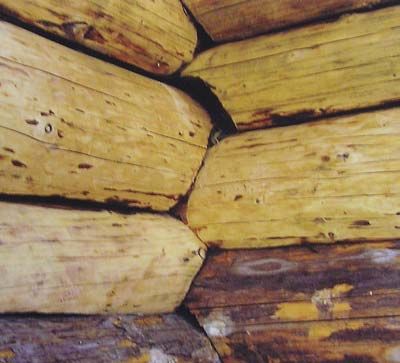
Physics of Constructions

                 http://www.ce.tuiasi.ro/intersections

                                                                             R. Musil

                                    units,…) and emergency equipments, for example lighting. This consumption
                                    depends mainly on time of running equipment.
                              Building or room occupation is independent parameter, user’s profile of one need
                              is usually independent on other variables (for example: energy consumption
                              doesn’t depend on waste water production). User’s profile strongly depends on
                              occupancy and time-current interval.

                              2.2. Models type of people behavior in the building
                                  • fixed profile which depends on time: day, weekday, month (we are taking into
                                    consideration leave and arrival time, weekdays plan and holidays)
                                  • stochastic models based on Markov chains, which are giving probably
                                    transition from one state to another, are processed on real dates in similar
                                    building type.
                                  • empiric models based on obtaining information from real dates of occupancy
                                    in similar building.

                              2.3. Description principles of building loads
                              Buildings loads which depended on human factor we call stochastic processes.
                              Stochastic processes are such process where are physical laws supplying laws of
                              probability which are showing for random time interval probability values. The
                              processes are developing randomly from one to second state and future these states
                              is possible to determine only on the basis probability.
                              For description these states are using Markov chains which are stochastic processes
                              with final number of states where is time divided on individual time intervals.
                              Markov chains are possible to use only when it discharge following condition:
                              “Future development of process depends only on existent process state and no on
                              its history.

                              2.4. How do we use Markov chains?
                              Mainly idea this method is building matrixes (Markov matrix) which expressive
                              probability of process in time interval which is going from the one state to another
                              state during next time step. Every element Pij(t) represent probability of change
                              process from state i in time t to state j in the future time step t+1, which we call
                              “change probability” state i to state j.
                              Theory of Markov chain gives information to us about probability behavior of
                              process and calculation “static vector of probability”. This vector gives probability
                              apparition each state in long-time interval.

ISSN 1582-3024                Article No.21, Intersections/Intersecţii, Vol.3, 2006, No.4, “Physics of Constructions”   6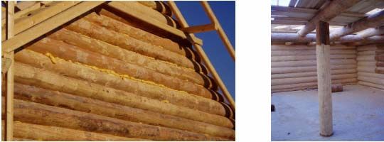
Physics of Constructions

                 http://www.ce.tuiasi.ro/intersections

                                                            Building system loads and its climatic data

                              2.5. Model
                              It is necessary to have enough dates in acceptably period which will designate and
                              probability of use. We have to determinate time step about which we interest and
                              we have to be sure that it is possible to obtain data with time results. Because this
                              method use union of discreet states, we need again to group parameters values to
                              final number intervals where every interval is termed represent values (often it is
                              maximum, minimum, or average value from the interval) We can use dates for
                              derivation to transition probability as per cent of incident which we interest and
                              total number of events. Now we have “catalogue” of transition probability from
                              one state to other. Next it is possible use this information for simulation behavior
                              of parameters by simple method which is calling reverse method.

                              3. CLIMATIC DATA, ITS FORMATS AND USE IN THE
                                 SIMULATION COMPUTER PROGRAM
                              Except people behavior in the building, exterior climatic conditions influence
                              energy and environmental building systems loads modeling. It influences
                              consumption of energy for heating and cooling by these exterior conditions.
                              Climatic conditions are simultaneously impulse for user which for example in
                              summer, when it is hot, switches on air-conditioning or ventilator.
                              In winter user can increase temperature on term regulator in required room or
                              heating sources output. Public notice 152/2001Sb. establishes rules for heating and
                              assessment consumption of energy. This notice fixes start (1. September) and end
                              (31. May) of heating period. Heat supply starts in heating period, when average
                              daily temperature of exterior air goes down below 13°C in two tandems following
                              days and cannot expect increasing this temperature above 13°C for following day.
                              Heat consumption is currently assessing by day-degrees method where we know
                              number of days and average exterior temperature in heating period for every
                              locality.
                                                                        24Qc • ε • D
                                                            QVYT ,r =                [Wh / rok ]                        (1)
                                                                          t is − t e
                              where:
                                  QVYT ,r - yearly need of heat [Wh/rok]
                                  Qc - heat loss of building [W]
                                  ε - correction factor
                                  D - number of day-degrees [d.K]
                                  tis - average interior temperature [°C]

ISSN 1582-3024                Article No.22, Intersections/Intersecţii, Vol.3, 2006, No.4, “Physics of Constructions”   7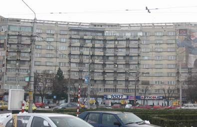
Physics of Constructions

                 http://www.ce.tuiasi.ro/intersections

                                                                               R. Musil

                                  te - calculating exterior temperature (it is assigned according to locality). [°C]

                                                                          D = (tis-tes)·d                               (2)
                              where:
                                tes - average exterior temperature in heating period [°C]
                                d - number of days in heating period [-].
                              A Day-degrees pattern shows that it is two-times influenced by climatic dates.
                              Firstly, average exterior temperature and than number of days in heating period are
                              influenced. Number of days in heating period is possible to determine returnly for
                              each heating period.
                              Nowadays average daily exterior temperature is assessed as:
                                                                            t 7 + t14 + 2 • t 21
                                                                   t ed =                                               (3)
                                                                                      4
                              Nowadays, when it is going to building-up development from thermal properties
                              aspect of building, this assessment way is unsatisfactory. Using existing average
                              exterior temperature by very good insulated building leads to deviation of
                              calculated and real values. Today, it is setup in some meteorological stations
                              automatic monitoring and writing climatic dates.
                              By using existing thermal average, it is necessary to make a difference between
                              average daily temperatures, average monthly temperatures and thermal average of
                              individual years. The long-term average values show smaller fluctuations of
                              temperatures. The daily average exterior temperature is assessed from measured
                              values:

                                                                                 ∑
                                                                                     e = 24
                                                                                                te
                                                                        t ed   =     e =1
                                                                                                                        (4)
                                                                                     24
                              We can obtain average exterior temperature in heating period tes from this
                              assessment daily average exterior temperature

                                                                                 ∑
                                                                                     d =n
                                                                                     d =1 ed
                                                                                            t
                                                                        t es   =                                        (5)
                                                                                     d
                              where d is number of days in heating period.
                              Using average daily exterior temperature is by using spreadsheet program possible
                              and calculated value of energy consumption is most approached to real energy
                              consumption. Use of average hourly temperatures is possibility of next
                              improvement of energy consumption. The average hourly temperatures for heating

ISSN 1582-3024                Article No.21, Intersections/Intersecţii, Vol.3, 2006, No.4, “Physics of Constructions”   8
Physics of Constructions

                 http://www.ce.tuiasi.ro/intersections

                                                            Building system loads and its climatic data

                              period are used in simulating programs with using climatic databases due to big
                              number of this values (for example: TMY, IWEC, WEA,…etc.)

                              4. TYPICAL METEOROLOGICAL YEAR
                              It is most significant format of climatic dates. It is a group of meteorological dates
                              with values for typical year which is making from selection month of separate
                              years (long-time measured during 30 or 50 years). Individual selections are linked
                              to typical meteorological year format. Typical meteorological year has two format
                              types: TMY and TMY2. In this formats are including hourly and monthly dates.
                              Every file have to obtain head with title of measured station, WBAN number (this
                              is identification number of station), town, state, time zone, latitude, longitude and
                              camber. For get date it is necessary to know its position in the column, type of date
                              and range their values. Measured dates are divided to groups. A-D is calibration
                              measured dates, E-I is data which isn’t directly measured, but it are generating by
                              other inputs or are obtaining from prediction models. Further are data divided to
                              groups (1-9) according to uncertainly of measured or generation where the group 1
                              has smallest % uncertainly.
                              Mainly dates of meteorological year:
                                • dry-bulb temperature
                                • dew point temperature
                                • relative humidity
                                • static pressure
                                • direct solar radiation
                                • diffusion solar radiation
                                • global solar radiation
                                • wind direction
                                • wind speed
                                • precipitation
                                • cloudiness
                              TMY and TMY2 has different time format and units hence isn’t possible change it.
                              Sometimes is directly and complex data hard to obtain or it is available in other
                              format which we need. In this case we have to use for example Weather manager
                              which can analysis and conversation to other dates formats. Among most supported
                              dates formats is:
                                 • TMY Climate Data (TMY)
                                 • TMY2 Climate Data (TMY2)
                                 • Energy plus weather files (EPW)
                                 • Weather data file (WEA)

ISSN 1582-3024                Article No.22, Intersections/Intersecţii, Vol.3, 2006, No.4, “Physics of Constructions”   9
Physics of Constructions
http://www.ce.tuiasi.ro/intersections
R. Musil
DRY BULB TEMPERATURE - , CZE 1st January to 31st December
°C °C
40 40
30 30
20 20
10 10
0 0
-10 -10
14th 28th 14th 28th 14th 28th 14th 28th 14th 28th 14th 28th 14th 28th 14th 28th 14th 28th 14th 28th 14th 28th 14th 28th
Jan Feb Mar Apr May Jun Jul Aug Sep Oct Nov Dec
DAILY CONDITIONS - 1st January (1)
°C W/ m˛
40 1.0k
30 0.8k
20 0.6k
LEGEND 10 0.4k
Comfort: Thermal Neutrality
Temperature Direct Solar 0 0.2k
Rel.Humidity Diffuse Solar
Wind Speed Cloud Cover
-10 0.0k
2 4 6 8 10 12 14 16 18 20 22 24
Figure 1. Example of graphic representation TMY which is generation from the Weather
data manager
5. CONCLUSION
Using input data in simulation calculations is one from dominates element which
determines result quality and its application for practice. Building face, its
structural solution or acquisition costs, aren’t only important by new projects
realization. Nowadays, when continually grow energy costs and environmental
importance increase, we are essentially more interested in real building service
during its lifetime. It is important to consider building working state, already at
projection documentation. Simulating programs are used for expectant building
behavior. Every simulating program is as good as good are used input data. This
paper shows overview of input data which are necessary to compile for
characteristic building types.
Acknowledgements
This paper presented results supported by Research Plan CEZ MSM 6840770003.
ISSN 1582-3024 Article No.21, Intersections/Intersecţii, Vol.3, 2006, No.4, “Physics of Constructions” 10Physics of Constructions
http://www.ce.tuiasi.ro/intersections
Building system loads and its climatic data
References
1. SunTool Report – Apríl 2006.
2. Notice 151/2001, sb.
3. User's Manual for TMY2.
4. Kabele, K., Musil, R., Analysis Consumption of Water in Residential building, Czech Plumber,
2006, CTU in Prague , ISSN 1210-695X.
5. Musil, R., Climatic Dates for Simulation Internal Environment, Proceedings of Indoor Clime of
Building 2005, Bratislava, ISBN 80-89216-05-6.
ISSN 1582-3024 Article No.22, Intersections/Intersecţii, Vol.3, 2006, No.4, “Physics of Constructions” 11Physics of Constructions
http://www.ce.tuiasi.ro/intersections
Present trends and potentialities in designing of log-houses
external walls
Hana Brandejsová and Miloslav Novotný
Department of Building Structures, Brno University of Technology, Brno, 662 37, Czech Republic
Summary
The paper deals with designing of log-houses external walls with the viewpoint of
thermal material characteristics. Timber is the natural material with the specific
properties such as volumetric changes caused by drying-out. That fact has to be
taken in account already during the design period. Window, door and stairs claim
the correct and elaborated details of horizontal log joints.
One of the chapters refers to the incorrect solved details of log house.
In the contemporary building classification, according to LCA (Life Cycle
Assessment), the log houses are ranked in very high position. Energy intensity of
the construction life is calculated since the building material production, through
the service till the demolition and removal.
The report deals with present trends in designing of the external walls of log
houses.
KEYWORDS: log houses, external walls, thermal material properties, volumetric
changes, round timbers.
1. INTRODUCTION
Recently, building of the classic log-houses becomes to be famous. This type of
construction is typical especially for Scandinavia and Canada, where roughly 85 %
of buildings are built from wood or wooden basis materials. In former times, the
wooden houses were fully occurring in the area of Czech Republic but later on,
wood had been jostled away by new materials, e. g. steel, concrete, glass. Within
the years of wood declining, the original traditions and continuity of for centuries
forwarding information had been broken and so we can say, building of long-
houses is quite new in our regions nowadays.
That is why the research and progress in designing of problematic details and
edification of log-house producers and lay public is so important. Many failures
that can occur within the log-house service period are caused by specific wooden
characteristics neglected when the structure have been constructing.
ISSN 1582-3024 Article No.22, Intersections/Intersecţii, Vol.3, 2006, No.4, “Physics of Constructions” 12Physics of Constructions
http://www.ce.tuiasi.ro/intersections
Present trends and potentialities in designing of log-houses external walls
Timber is as a natural material sensitive to biotic and abiotic damages. These
disadvantages are overcharged by relative source availability of sustainable
material source, workability, by pleasant feature, and last but not least, by easy way
how to dispose.
Lately, there are all over the world increasing demands for usage of environmental
friendly and permanent available materials. Just timber is a material that satisfies
these requirements.
2. EXAMPLES OF INCORRECT DETAILS
Figure 1. Left –Incorrect construction and insulation of gable; Right –Incorrect placing of
vertical element (an adjusting screw is missing)
Figure 2. Incorrect corner structure (roughly encircled shapes)
ISSN 1582-3024 Article No.22, Intersections/Intersecţii, Vol.3, 2006, No.4, “Physics of Constructions” 13Physics of Constructions
http://www.ce.tuiasi.ro/intersections
H. Brandejsová, M. Novotný
3. DESIGNING OF THE LATERAL GROOVES
3.1. Termal-technical requirements
Recently, still increasing values of thermally technical construction requirements
are heavily discussed among the construction specialist. Light framework
constructions can be easily insulated by required thickness of insulator. The log-
houses have different behavior – timber has a specific ability to accept and
eliminate the moisture content in dependence with interior air relative humidity.
Against that, totally insulated and closed buildings require to be furnished by
forced ventilation system that ensures regular interior air changing and clear the
interior air to anticipate the condensation and mould rises at the sensitive places.
Log walls are built up from logs of diameter 350 – 400 mm to meet standard
ČSN 730540. The thermal resistance of wall is defined by the log diameter and tree
species. However, the lateral grooves are staying the problematic details.
3.2. Insulation material
The lateral joint of two logs has to be designed in such a way to ensure as tight and
stable barrier between interior and exterior as possible. The material used for
jointing of lateral grooves has to guarantee to thermal-technical properties from the
point of view of both thermal resistant and air infiltration. At once, the material has
to show shape recovery that means it has to be able to follow the working of wood
(swelling and shrinkage). Each log that is inbuilt with moisture content higher than
19 % has to be provided by longitudinal kerf. These kerfs cut on the top of logs
show an effective way to control the location of checks as green logs dry. The
depth of the kerf shall be at least one-quarter of the log diameter, and shall be no
deeper than one half of the diameter.
Primarily, PUR foam was using for sealing of the grooves and notches. This
material is shape stable when hardening that means it cannot respond to the
woodworking, consequently cracks appear and need to be repair time to time. That
is why this material is no more used. Today, two-level insulating is common used;
it can be seen on the picture nr.1 - left. The mineral wool is embedded into the
continuous lateral groove and protected by joint sealing tapes from both sides. The
tapes are made from permanent elastic material on the base of modified rubber
foam, which is impregnated to resist UV radiation and eliminate an absorbing
power. Such a gasket shall also restrict the water, air and insect infiltration.
Recently, usage of fleece instead of mineral wool is considering in Czech Republic.
This natural material has to be necessarily proofed in insect resistance. The subject
of further research is a fleece availability and effectiveness within the gaskets
problematic.
ISSN 1582-3024 Article No.22, Intersections/Intersecţii, Vol.3, 2006, No.4, “Physics of Constructions” 14Physics of Constructions
http://www.ce.tuiasi.ro/intersections
Present trends and potentialities in designing of log-houses external walls
For comparison, the incorrect type of groove is shown on the picture nr. 1- right,
there is neither notch nor insulation in the groove.
MINERAL WOOL JOINT SEALING TAPES
Figure 3. Examples of correct and incorrect groove type
4. MEASUREMENT
To obtain enter values necessary for further design analysis, the thermo vision
measurement and surface temperatures measurements of log walls were realized.
Shown outputs are from the log wall, where only the pairs of joint sealing tapes
protect the grooves. There is no thermal insulation.
Figure 4. Thermo camera outputs – outside view
From the upper two graphs, the obvious difference between the log surface and
groove temperature can be seen.
ISSN 1582-3024 Article No.22, Intersections/Intersecţii, Vol.3, 2006, No.4, “Physics of Constructions” 15Physics of Constructions
http://www.ce.tuiasi.ro/intersections
H. Brandejsová, M. Novotný
The subject of further research is an optimization of groove design with the point
of view in thermal engineering.
Figure 5. Surface temperature measurement outputs
5. ENVIRONMENTAL CLASSIFICATION
Recently, general attitude towards the environment is changing and also the civil
engineering sphere is looking towards to original material base comeback. Also
within the construction materials and elements classification, the environmental
aspects have rising importance beside the technical and economical aspects. Effects
on environment caused by usage of definite material have to be considered during
the whole life element period.
The international reputable system for material and buildings classification is so
called Life Cycle Assessment – LCA. To be the project certificated as an ISO
suitable, the requirements of series ISO 14040 should not be omitted. Standards
describe methods needed for Life Cycle Assessment generation. These are
especially ISO 14040 Goal and scope, ISO 14041 Life Cycle Inventory Analysis,
ISO 14042 Life Cycle Impact Assessment and ISO 14043 Life Cycle
Interpretation.
In practice this means that the fossil energy consumption used in building
constructions should be reduced. The total fossil energy consumption does not only
compose of coal and gas but this is a complex question of choice of particular
material types, which had been produced with the aid of fossil energy. For that
reason, as much renewable sources should be used for the constructing as possible.
Wood is undoubtedly ranked among these low energy renewable materials.
ISSN 1582-3024 Article No.22, Intersections/Intersecţii, Vol.3, 2006, No.4, “Physics of Constructions” 16Physics of Constructions
http://www.ce.tuiasi.ro/intersections
Present trends and potentialities in designing of log-houses external walls
6. CONCLUSIONS
From the point of view of recently LCA classification, the log houses are ranked
among the energy modest construction. That is because wood is an easy available
and renewable material, log houses production is easy while the construction
details are finished in correct way, their operation is also quite unpretending and
last but not least, they cause minimal environment pollution. Wood is a renewable
natural source and that is why is so contradistinguished from other construction
materials.
References
1. Houdek, D., Koudelka, O., Srubové domy z kulatin, ERA group spol.s r.o., Brno 2004. (in Czech
Republic)
2. Novotný M., Expert’s report 53-09/05 About current state of carcassing of family house , Brno
2005. (in Czech Republic)
3. Přeček, L., Doctoral thesis – Podpora pro navrhování vícepodlažních dřevostaveb, ČVUT Praha
2005 (in Czech Republic)
4. Houdek, D., Conference proceedings - Dřevostavby, VOŠ a SPŠ Volyně 2005 (in Czech
Republic)
ISSN 1582-3024 Article No.22, Intersections/Intersecţii, Vol.3, 2006, No.4, “Physics of Constructions” 17Physics of Constructions
http://www.ce.tuiasi.ro/intersections
Indoor climate in contemporary buildings
Lenka Másilková
Dept. of Microenvironmental & Bldg. Services Engrg., CTU, Prague, 166 29, Czech Republic
Summary
Microclimate in contemporary residential buildings is nonconforming, because
packaging constructions are too tight. In the aspect of presence of people is the
most important thermal-moisture microclimate.
To guarantee optimal temperature in an interior can be quite simple, but to achieve
optimal relative humidity can be problematic. But mildew emerges from higher
relative humidity. It is important to guarantee sufficiency of ventilation air in the
rooms, especially in winter period. Winter is the highest-risk period for increasing
the relative humidity and following arise of the mildew.
This entry is comparing results of intensity of natural ventilation in various types of
contemporary buildings.
KEYWORDS: indoor climate, contemporary buildings, relative humidity, natural
ventilation, exfiltration, infiltration
1. INTRODUCTION
This entry intends to verify the authenticity methodology of computation of
buildings ventilation. It especially determines more accurately interdependence
parameters of leakage window chink of ventilated room size in the case of meeting
existing hygienic requirements and conditions for protecting engineering
construction (such requirement is for example moisture outlet).
At computations air change rate was not taken into account effect of under pressure
ventilation bathroom and toilet to other rooms. Considering limited range of this
article it is impossible to describe all the computations, which we have made. To
make the computations more understandable I added a table to the last part of each
of them.
Below in the text I am using a help term „diagonally ventilated flat“. Diagonally
ventilated flat is a flat, which windows are situated on the opposite sides of
building facades. On the contrary not diagonally ventilated flat has windows only
on one facade.
ISSN 1582-3024 Article No.23, Intersections/Intersecţii, Vol.3, 2006, No.4, “Physics of Constructions” 18Physics of Constructions
http://www.ce.tuiasi.ro/intersections
Indoor climate in contemporary buildings
As basis of computations all three examples of natural ventilated rooms are taken
into account flat 3+1. Disposition of this flat in a panel house has total volume of
all the rooms 160m3.
2. VENTILATION IN CONTEMPORARY BUILDINGS
2.1. Problems of heat consumption for ventilation
Almost 4 million people in the Czech Republic live in panel houses. Majority of
older panel houses are not corresponding to the standard ČSN 73 05 40 (thermal
buildings protection) nowadays. Expensive reconstructions of panel building are
passing through – heat cladding facades, changing original wooden windows to
plastic, glazzing loggia as well. We are packing flats to save money for energy.
But how big is the importance of these changes to the flat natural ventilation? Well,
all the buildings are so tight now that the infiltration rate is so minimal – the air
supply by the chink in construction’s blocking.
Nevertheless each household is producing moisture – by evaporating from the
flowers, by cooking, by bathing etc. As far as the draining away of this moisture is
not solved, due to it can be inception of moisture and degradation of engineering
construction (rot). There is only one possible solution how to reduce relative
humidity. It is ventilation, which at the same time ventilates others injurants from
the interior (CO2, formaldehyde etc.) and ensures the supply fresh air into the flat.
Is it possible to count only on infiltration by window chink in so tight objects?
Does not mean heat cladding facade, new tighter windows, possibly glazed loggia
periodical opening the windows for ventilation, so that to ventilate the room
actually?
Will not be necessary to wake up each 1,5 hour and perfectly air all the room?
In this entry author presents how much energy do we use up for prescribed
necessary hygienic need on air change rate in the room. How does differ from each
other the heat consumption for ventilation by infiltration, exfiltration or standard
0,5times air change rate per hour for definite flat in the panel house?
2.2. Ventilation by wind with its different speed during the year –
INFILTRATION
The main part of the wind effect ventilation in the flat takes not only the wind
speed, but the flat position too. We consider a wind speed in variants of 2,5m/s;
5m/s; 10m/s.
ISSN 1582-3024 Article No.23, Intersections/Intersecţii, Vol.3, 2006, No.4, “Physics of Constructions” 19Physics of Constructions
http://www.ce.tuiasi.ro/intersections
L. Másilková
The air change rate in the flat grows according to the velocity of wind. Flats in the
ground floor of the buildings are mildly ventilated by wind in comparison with the
flats in the upper floors, which are ventilated intensively.
It is valid the rule of wind influence to the buildings. Wind speed is increasing with
the building height. And that is why the flat in the eight floor is more ventilated
then the flat situated in the first above-ground floor.
Figure 1. Ground plan of the flat – wind effect ventilation - INFILTRATION
Of course we consider flat position in the computations. We choose different
coefficient leakage window chink and variants closed or opened interior doors in
the flat in computations as well.
2.3. Ventilation by static pressure effect in the stair’s shaft –
EXFILTRATION
Lower flats are intensively ventilated, namely at not tight openings and chinks in
the upper part of stair’s shaft. When the inner stair’s shaft is connected through the
flats on exterior the ventilating air from the lower flats can get into the upper flats
namely when
• Entry flat’s door is not tight
• Lower flat’s windows are not tight or opened
For ventilation by static pressure effect in the stair’s shaft is important that
• Upper flats are practically not ventilated from the exterior. But air is pressed
from lower flats to upper flats through the stair’s shaft (by inner stair’s shaft).
• On the contrary lower flats are intensively ventilated by exterior air, the air is
sucked up to them under pressure through the stair’s shaft.
ISSN 1582-3024 Article No.23, Intersections/Intersecţii, Vol.3, 2006, No.4, “Physics of Constructions” 20Physics of Constructions
http://www.ce.tuiasi.ro/intersections
Indoor climate in contemporary buildings
Figure 2. Ground plan of the flat – ventilation by static pressure effect in the stair’s shaft -
EXFILTRATION
Figure 3. Section across the building – ventilation by static pressure effect in the stair’s
shaft - EXFILTRATION
ISSN 1582-3024 Article No.23, Intersections/Intersecţii, Vol.3, 2006, No.4, “Physics of Constructions” 21Physics of Constructions
http://www.ce.tuiasi.ro/intersections
L. Másilková
2.4. Ventilation by combination of wind effect and stair’s shaft effect
Combination of wind effect and stair’s shaft effect compensates fair extremes in
upper and lower flats (we do not include this combination in computations)
• Low – small wind effect and up – meaningful stair’s shaft effect.
• Up – meaningful wind effect and low – small stair’s shaft effect (under
pressure against to excess pressure from the wind).
2.5. Ventilation by standard 0,5times air change rate per hour
Hygienic requirement for ventilation by standard 0,5times air change rate per hour
lets
• By relatively small total volume of the room and small length window’s
chink, for example in panel building bigger infiltration coefficient iLV
(classic value coefficient leakage for original wooden windows is 1,4*10-4
m-2 s-1 Pa-n). From the energetic point of view in panel buildings is not
necessary to plant tight windows.
• By relative large total volume of the room in old buildings (high room’s
headroom) and large length window’s chink could be smaller infiltration
coefficient iLV (tightly windows).
3. AIR CHANGE RATE – COMPUTATIONS
End computation conditions: we consider a flat with a total volume of 160 m3 (area
with 64m2 and height of 2,5m).
Rooms are ventilated by natural infiltration or exfiltration effect. MS Excel makes
all the computations.
Entry value, inter computations and results are elaborated in well-arranged tables
with particular descriptions of quantities, formulas and at the end comparing end
values with standard values.
4. HEAT CONSUMPTION FOR VENTILATION -
COMPUTATIONS
Computations about heat consumption for ventilation are elaborated in three
variants air change rate in the flat.
ISSN 1582-3024 Article No.23, Intersections/Intersecţii, Vol.3, 2006, No.4, “Physics of Constructions” 22Physics of Constructions
http://www.ce.tuiasi.ro/intersections
Indoor climate in contemporary buildings
4.1. Heat consumption for ventilation by wind effect – INFILTRATION
When wind speed is higher, than heat consumption need is higher too, we have
higher heat consumption to secure the loss during the ventilation.
With the wind speed of 10m/s is used up to 47% heat consumption quantity
from total heat quantity.
Table 1. Ventilation by wind effect force with different wind speed during the year
wind percentage hour exterior interior ventilation air (ti-te)*0,36 power heat
speed share number temperature temperature volume quantity
c x h tem ti Vv Q Qc
3
m/s % h ( °C ) ( °C ) m /h W kWh
1 2,5 30 1800 4 20 20,36 5,76 117,27 211,09
2 5 15 900 4 20 81,46 5,76 469,21 422,29
3 10 5 300 4 20 325,84 5,76 1876,84 563,05
50% = 3000 hours from 6000 hours in heating period 1196,43
4.2. Heat consumption for ventilation by static pressure effect in the stair’s
shaft – EXFILTRATION
• To secure the loss during the ventilation is needed the biggest heat
quantity, when the exterior temperature is -2,2 °C. It is 55 %.
• At the same time this maximum is raised by the fact that the temperature of
-2,2 °C secures 118 days from 240 days in heating period.
• It is 50% of days in the heating period.
Table 2. Ventilation by static pressure effect in the stair´s shaft
interior air exterior day (273+te) 273 1,293*273 shaft´s (ρe-ρi) static ventilation air power heat
density temperature number (273+te) (273+te) high pressure volume quantity
ρi(20°C) t x ρe(při x°C) H pH Vv Q Qc
kg/m3 ( °C ) kg/m3 m Pa m3/h W kWh
1,205 -15 6 258 1,058 1,368 15 0,163 24,476 31,53 397,28 57,21
1,205 -9,4 19 263,6 1,036 1,339 15 0,134 20,116 25,77 272,75 124,37
1,205 -2,2 118 270,8 1,008 1,304 15 0,099 14,776 18,84 150,57 426,41
1,205 1,8 52 274,8 0,993 1,285 15 0,080 11,930 15,19 99,52 124,21
1,205 7,4 37 280,4 0,974 1,259 15 0,054 8,081 10,19 46,22 41,04
1,205 11,2 18 284,2 0,961 1,242 15 0,037 5,557 7,11 22,52 9,73
day sum = 250 total heat quantity QSUMA = 782,98
4.3. Heat consumption for ventilation by standard 0,5times air change rate
per hour
• Results are percently agreeing with example 4.2
• To secure the loss during the ventilation is needed the biggest heat quantity,
when the exterior temperature is -2,2 °C. It is 54 %.
• At the same time this maximum is raised by the fact that the temperature of -
2,2 °C secures 118 days from 240 days in heating period.
ISSN 1582-3024 Article No.23, Intersections/Intersecţii, Vol.3, 2006, No.4, “Physics of Constructions” 23Physics of Constructions
http://www.ce.tuiasi.ro/intersections
L. Másilková
• It is 50% of days in the heating period.
Table 3. Ventilation by standard 0,5times air change rate per hour
exterior day interior air change flat ventilation air n*Vv*0,36 temperature power heat
temperature number temperature rate volume volume difference quantity
t x ti n V Vv ti-te Q Qc
-1 3 3
( °C ) ( °C ) h m m /h ( °C ) W kWh
-15 6 20 0,5 160 80 28,8 35 1008,00 145,15
-9,4 19 20 0,5 160 80 28,8 29,4 846,72 386,10
-2,2 118 20 0,5 160 80 28,8 22,2 639,36 1810,67
1,8 52 20 0,5 160 80 28,8 18,2 524,16 654,15
7,4 37 20 0,5 160 80 28,8 12,6 362,88 322,24
11,2 18 20 0,5 160 80 28,8 8,8 253,44 109,49
day sum = 250 total heat quantity QSUMA = 3427,80
5. CONCLUSIONS
• The highest heat consumption provides ventilation by standard 0,5 times air
change rate per hour
• At the same time maximal heat quantity is value, which is needed for perfect
flat airing, it means to hold the norm standard 0,5 times air change rate per
hour
• Airing by INFILTRATION, with the same entry conditions, air change rate is
only 0,175 times per hour
• Airing by EXFILTRATION, the flat is ventilating only 0,115 times
Table 4. Results comparing – computations heat consumption for ventilation
heat percentage air change
quantity share rate
Qc heat n
kWh quantity h-1
INFILTRATION 1196 35% 0,175
EXFILTRATION 783 23% 0,115
n = 0,5per hour 3428 100% 0,5
maximum
After comparing the results of total heat consumption we are satisfied that maximal
heat quantity (that is 55% from total heat consumption) is important to supply
when the exterior temperature is -2,2 °C.
This percentage share completely corresponds with percentage share day number
during heating period while different exterior temperatures. Day number during
heating period while exterior temperature is -2,2 °C, it is to 50%. And it is the same
ISSN 1582-3024 Article No.23, Intersections/Intersecţii, Vol.3, 2006, No.4, “Physics of Constructions” 24Physics of Constructions
http://www.ce.tuiasi.ro/intersections
Indoor climate in contemporary buildings
in the case of stair’s shift effect and standard 0,5times air change rate per hour too.
In both cases is used about 55% from total heat consumption.
We are satisfied that room’s ventilation by standard 0,5times air change rate per
hour is the most energetic expensive.
Total heat consumption for ventilation by standard 0,5 times air change rate per
hour is 100%. This energy cost we could theoretically decrease by calculated
heating loss by infiltration (35%) and exfiltration (23%). We can decrease total
heat quantity by heat quantity from wind effect (infiltration) and stair’s shaft effect
(exfiltration). Percentage share 58% (35% + 23%) is more than a half needed heat
quantity. This result we cannot neglect.
Total air change rate can we compute by this equation (1). Air change rate
0,79times per hour in this case is much more than hygienic requirement presents.
n0,5 + nINFIL. + nEXFIL. = nTOTAL [h-1] (1)
0,5 h-1 + 0,175 h-1 + 0,115 h-1 = 0,79 h-1
Because natural ventilation is passing through all the time in parallel with
controlled standard 0,5 times air change rate per hour. If we do not accept natural
ventilation, the room will be ventilated more than hygienic minimum.
Controlled standard 0,5 times air change rate per hour is the most energy
consuming. We can decrease total heat quantity by heat quantity from wind effect
(infiltration) and stair’s shaft effect (exfiltration). It is computed in second equation
(2).
Qn0,5 - QnINFIL. - QnEXFIL. = QnTOTAL [kWh-1] (2)
100% - 35% - 23% = 42%
We are satisfied that total heat quantity can bee decreased more than to half.
Acknowledgements
This research has been supported by MŠMT grant No. MSM 6840770005.
References
1. Jelínek, V., Micro environmental and building services engineering, 2nd ed. Prague: University
press ČVUT, 2004. 158 s. ISBN 80-01-02887-9.
2. Norm Thermal building protection – ČSN 73 05 40
ISSN 1582-3024 Article No.23, Intersections/Intersecţii, Vol.3, 2006, No.4, “Physics of Constructions” 25Physics of Constructions
http://www.ce.tuiasi.ro/intersections
CFD simulation of indoor climate
Ondřej Šikula
Institute of Building Services, Brno University of Technology, Brno, 602 00, Czech Republic
Summary
The paper presents the experience acquired by the CFD (Computational Fluid
Dynamics) simulation of indoor climate in a room heated by a gas space heater.
The vertical air temperature difference in room is one of the indoor climate
parameters. The simulation presents the non-stationary airflow and the distribution
of temperatures in a dwelling room. The main goal of the paper is to identify
factors which make a great vertical air temperature difference. Especially in a
room which is heated up with high temperature of air. The paper compares results
of CFD simulation with the measuring of temperatures and velocities in this room.
The results can be considered trustworthy only if proper models of turbulence and
radiation are used. The next goal is finding out appropriate turbulence and
radiation models which could describe both heat transfer mechanisms in the room.
The simulation is solved in the computer program FLUENT.
KEYWORDS: CFD simulations, indoor climate, dwelling room
1. INTRODUCTION
1.1. Indoor climate
The main goal in the field of environmental engineering is to ensure optimal
conditions for work, relaxation and residence of people in buildings. Optimal
conditions are created artificially by means of heating, ventilation and air-
conditioning systems. In this connection we speak about creation of the indoor
climate in buildings which can be distinguished as thermal-technical, lighting,
acoustic, etc.
The substantial part of HVAC designer’s work constitutes the ensuring of the
proper thermal and moisture microclimate in buildings. During winter and
transition periods this problematic is ensured by the field dealing with heating
systems. The humidity factor is in practice often omitted, therefore only the
thermal component of indoor climate is observed. For simplification the
problematic of the indoor climate creation during winter and transition period is
focused on residential buildings. Factors creating the thermal microclimate within
the room are especially temperature, intensity of thermal radiation and air
ISSN 1582-3024 Article No.24, Intersections/Intersecţii, Vol.3, 2006, No.4, “Physics of Constructions” 26Physics of Constructions
http://www.ce.tuiasi.ro/intersections
CFD simulation of indoor climate
turbulence level. The characteristic feature of all these factors is their distinctive
time and spatial variability. These physical factors are present in all parts of the
room and form the indoor climate of the room. By means of computer simulations
and practical measurements can be proven and shown that the state of indoor
climate generally varies at individual points of the room and different time periods
as well.
Practically it is important to observe the thermal microclimate within spaces
occupied by people. This area is designated as the inhabitant’s zone.
1.2. Vertical distribution of temperatures as a thermal comfort factor
One of the factors influencing the quality of indoor climate in a dwelling room is
the vertical distribution of temperatures. From now on the article deals with this
factor. Already the old literature gives attention to this topic. For example [1]
recommends the maximal temperature difference between the position of a head
(t1,7) and an ankle (t0,1) to be 2,0 K for standing person and 1,5 K for sitting
person from the point of view of thermal comfort. In Table 1, there are stated the
ascertained vertical temperature differences for various types of heating according
to [1]. The legal regulation for working environment requires the maximal vertical
temperature difference to be 3 K, see [5].
Table 1. Maximal vertical temperature difference for standing person
Type of heating Temp. difference between t1,7 a t0,1
Hot water heating – sectional heating element 1,5
Hot water heating – convector 2,7
Local heating – tiled stove 3,8
Warm-air heating 5,5
The requirement for thermal uniformity is easy to satisfy in case of floor heating,
well-designed warm-air hating, etc. Generally we can say that the requirement on
vertical temperature distribution is easily reachable when the temperature of the
heating surface is not too much higher than the temperature of air.
Problematic situations occur by heating systems which produce high temperature in
the vicinity of the heating surface. Around very hot heating surfaces
(approximately > 90 °C) occurs intensive flow of high air temperature caused by
the thermic lifting force. Consequently the vertical temperature difference in the
room is greater. Similar situation happens while heating with warm-air heating
systems.
ISSN 1582-3024 Article No.24, Intersections/Intersecţii, Vol.3, 2006, No.4, “Physics of Constructions” 27Physics of Constructions
http://www.ce.tuiasi.ro/intersections
O. Šikula
2. DESCRIPTION OF THE PROBLEM AND SOLUTION
This article deals with the theoretical and experimental assessment of vertical
temperature distribution in a room. We investigate the influence of the heating
system with large heating surfaces and high temperatures on the vertical
temperature distribution. The problem was solved theoretically and experimentally
on a model room in a brick house heated by a gas space heater. The goal is to find
out if the requirement on maximal vertical temperature difference according to [1]
between the position of a head and an ankle can be satisfied especially at non-
stationary conditions.
glass door outside wall
control line
window
section 1 tout
gas
convector
section 2
natural
outlets
natural
inlet
Figure 1. Geometry
Numerical simulation of the airflow and the heat transfer is carried out in the
computer software FLUENT on a simplified three-dimensional model of the room.
Theoretical solution
Theoretical solution is based on CFD simulation of the room created in the
software Fluent. The calculation is solved for non-stationary conditions and three-
dimensional case. The temperature boundary conditions of the model correspond to
the condition of the day when the experimental measurement was done. For
turbulence calculations the RNG k – e model was used. The heat transfer by long-
wave radiation was solved by DO (Discrete ordinates) model.
ISSN 1582-3024 Article No.24, Intersections/Intersecţii, Vol.3, 2006, No.4, “Physics of Constructions” 28Physics of Constructions
http://www.ce.tuiasi.ro/intersections
CFD simulation of indoor climate
τ=30 seconds τ=360 seconds
Figure 2. Unsteady temperature fields
Ext. Ext
Int. Int.
Figure 3. The creation of dropping airflow - section Nr. 1
Ext. Ext
Int. Int.
Figure 4. The shading out of dropping airflow - section Nr. 2
Simulation solution enables the illustration of temperature and velocity fields in the
analyzed model room.
ISSN 1582-3024 Article No.24, Intersections/Intersecţii, Vol.3, 2006, No.4, “Physics of Constructions” 29Physics of Constructions
http://www.ce.tuiasi.ro/intersections
O. Šikula
3. EXPERIMENT
Methods
The experimental measurement was taken in the winter period of 2005/2006 and
was divided in two parts. First of all were measured vertical temperatures in eight
height points in the symmetry plane of the room. At the same time the velocity and
temperature of air coming out of the gas space heater was measured and recorded.
Further the monitoring of temperature fields of building structure surfaces was
performed by the digital thermal-vision camera IR FLEXCAM.
The aim of the temperature, velocity and thermal-vision measurements was the
identification of some indoor climate parameters and partially the verification of
the numerical simulation results. The measurements proceeded as follows. First the
model room was pre-heated (see the first temperature wave at Figure 5).
Figure 5. Time flow of the experiment
By this pre-heating the “start” temperature profile of the room was obtained (see
the black vertical temperature distribution profile at Figure 6).
By gradual heating the maximal temperature profile was obtained (see the black
vertical temperature distribution profile at Figure 7). After shutdown of the gas
space heater the temperatures decreased (see the left vertical temperature
distribution profile at Figure 7).
ISSN 1582-3024 Article No.24, Intersections/Intersecţii, Vol.3, 2006, No.4, “Physics of Constructions” 30Physics of Constructions
http://www.ce.tuiasi.ro/intersections
CFD simulation of indoor climate
Figure 6. The vertical air temperature difference; warming-up
Figure 7. The vertical air temperature difference; cooling
ISSN 1582-3024 Article No.24, Intersections/Intersecţii, Vol.3, 2006, No.4, “Physics of Constructions” 31Physics of Constructions
http://www.ce.tuiasi.ro/intersections
O. Šikula
cooling curve
warming-up
Figure 8. Warming-up and cooling of the interior air temperature ti and its dependency on
the air temperature coming out of the gas space heater tout
Figure 9. The dependency of the air velocity coming out of the gas space heater on the
difference of air temperatures coming out of the gas space heater tout and the interior air
temperature ti
ISSN 1582-3024 Article No.24, Intersections/Intersecţii, Vol.3, 2006, No.4, “Physics of Constructions” 32You can also read