Pitched roof installation AK - For roofing tiles, plain tiles and slates Assembly Instructions
←
→
Page content transcription
If your browser does not render page correctly, please read the page content below
Photovoltaic Mounting Systems

                    Assembly Instructions

Pitched roof installation AK
    For roofing tiles, plain tiles and slates

     © S:FLEX GmbH 02/2021/ Technical changes reserved   1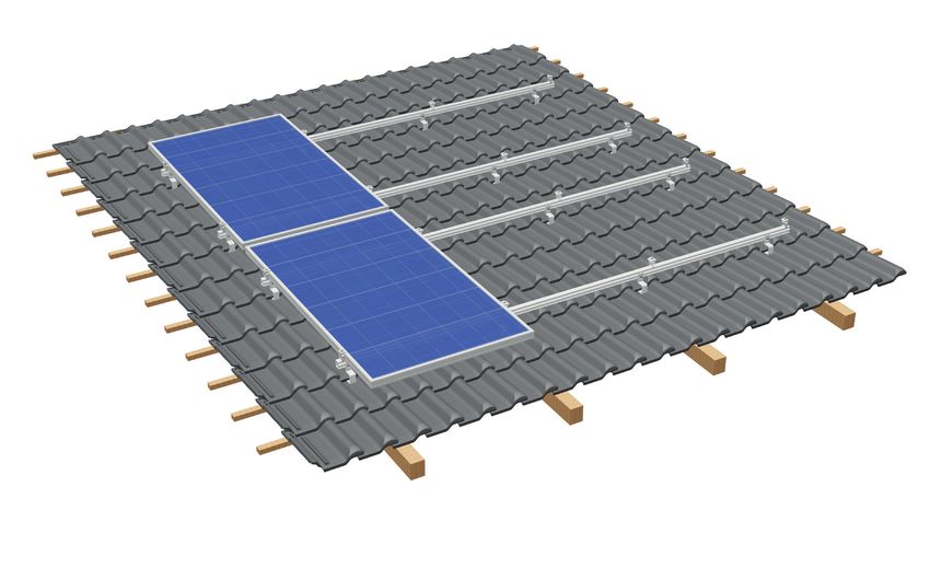
Table of contents

           1            Introduction

                        1.1       Intended use                                                                        3

                        1.2       About this document                                                                 3

                        1.3       Warnings                                                                            4

                        1.4       General information — standards and guidelines                                      4

                        1.5       Description of the system                                                           6

           2            Pitched roof installation AK

                        2.1       System components                                                                  11

                        2.2       Installing the roof hooks                                                          12
                                  2.2.1      Roof connection for roofing tiles                                       12
                                  2.2.2      Roof connection for plain tiles                                         16

                                  2.2.3      Roof connection for slates                                              18

                        2.3       Frame assembly                                                                     21
                                  2.3.1      Single-layer assembly in upright orientation                            21
                                  2.3.2      Double-layer assembly in transverse orientation                         25

                        2.4       Module installation                                                                29
                                  2.4.1      Module installation, vertical                                           29
                                  2.4.2      Module installation, transverse                                         34

           3            Disassembly and disposal

                        3.1       Disassembly                                                                        38
                        3.2       Disposal                                                                           38

           4            Terms of use and warranty

                        4.1       User agreement                                                                     39
                        4.2       Warranty / disclaimer                                                              39

S:FLEX GmbH • Reinbeker Weg 9 21029 Hamburg Tel. +49 (0)40 688 93 17 0 • Elsässer Str. 12 79189 Bad Krozingen Tel. +49 (0)761 888 56 08 0

info@sflex.com      www.sflex.com                                      © S:FLEX GmbH 02/2021/ Subject to technical modifications            2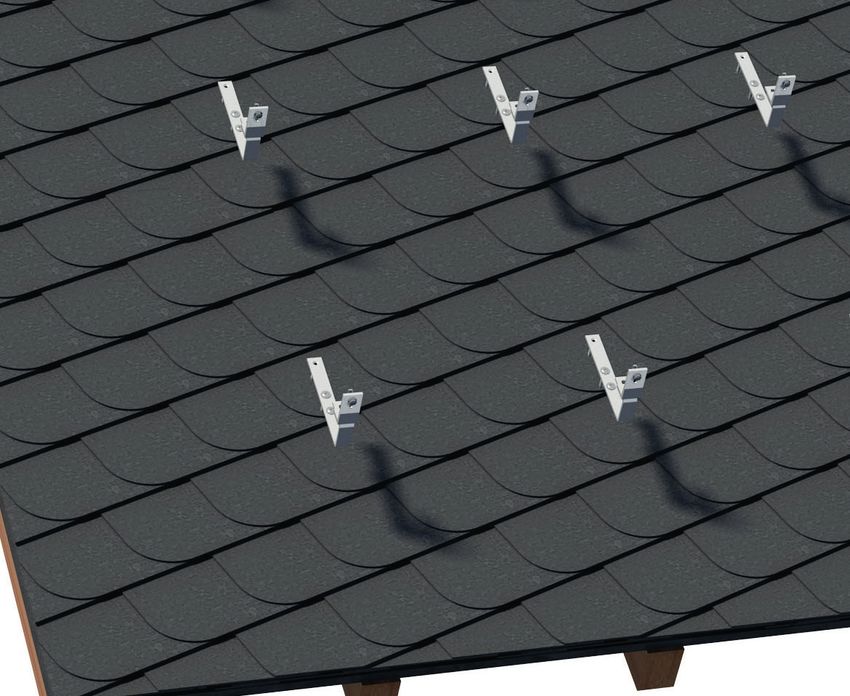
1       Introduction

Read these installation guidelines carefully before installing the S:FLEX mounting system and retain them for future
reference!
These installation guidelines are only complete with the project-specific implementation plans (project report)!

The S:FLEX PV fastening system for pitched roofs with roofing tiles, plain tiles and slate roofing is a frame system
for mounting PV modules. It consists of mounting rails, roof hooks and all necessary small parts for fastening the PV
modules on the mounting rails, for connecting the components to each other and for fastening to the roof substructure
(RS).
The S:FLEX mounting system allows upright or transverse installation of the modules. The modules can be mounted in
one or two rows.

An outstanding feature of the S:FLEX PV fastening system for pitched roofs with roofing tiles is the high availability of
pre-assembled parts. The patented and proven click technology ensures the shortest possible installation times.
All components are generally made of aluminium and stainless steel. Their high degree of corrosion resistance ensures
a long service life and offers the possibility of complete recycling.

1.1 Intended use

The S:FLEX PV fastening system for pitched roofs with roofing tiles, plain tiles and slate roofing is a frame system for
mounting PV modules. It is designed exclusively for the installation of PV modules.
Any other use in this regard is considered misuse of the product. Observance of the information in these installation
guidelines in particular, is a prerequisite for intended use.
S:FLEX GmbH accepts no liability for damage resulting from non-observance of the installation guide or from misuse or
incorrect use of the product.

1.2 About this document

This installation recommendation describes the installation of the pitched roof frame for roof coverings with roofing
tiles. For this purpose, the S:FLEX PV fastening system offers suitable solutions for easy connection to the existing roof
substructure. Within the scope of this installation recommendation, the installation options are described separately for
common roofing tiles:

         – Roofing tiles
         – Plain tiles
         – Slates

This document shows the installation recommendations for:

         – Single-layer assembly with framed PV modules in upright orientation
         – Double-layer assembly with framed PV modules in transverse orientation

It must be ensured that only current and complete installation guides are used for the installation process.

S:FLEX GmbH • Reinbeker Weg 9 21029 Hamburg Tel. +49 (0)40 688 93 17 0 • Elsässer Str. 12 79189 Bad Krozingen Tel. +49 (0)761 888 56 08 0

info@sflex.com      www.sflex.com                                      © S:FLEX GmbH 02/2021/ Subject to technical modifications            3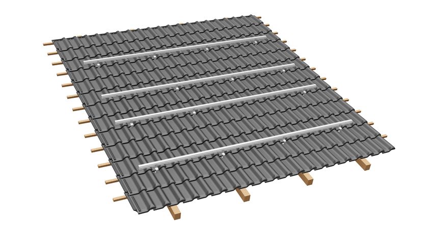
1       Introduction

1.3 Warnings

The warning texts provided in these installation guidelines relay safety-related information.
They are:

                 Unless observed, there is a major risk of
                 injury as well as a risk of death.

                 Non-compliance may lead to property damage.

1.4 General information - Standards and guidelines

Every photovoltaic system must be installed in accordance with the instructions contained in the respective installation
guidelines and the project report.
These installation instructions are based on state-of-the-art technology and many years of experience of installing
our systems on site. It must be ensured that only the current and complete installation instructions are used for the
installation, and that a print-out of the installation guidelines is stored in the immediate vicinity of the system. The
system and these guidelines are subject to technical changes.

The project report is part of the installation instructions and is created on a project-specific basis. All of the information
contained in the project report must be strictly observed. The project report contains the location-based static calculations.
The S:FLEX mounting system must be designed and created with the S:FLEX software (Solar.Pro.Tool).

Since individual project-specific features must be considered with every roof, expert advice must always be sought prior
to installation. Before installation, the PV system creator must ensure that the existing roofing and roof substructure
are suitable for the additional loads. The condition of the roof substructure, the quality of the roof covering and the
maximum load-bearing capacity of the roof construction must be checked by the system creator.
Contact a local specialist installer or structural engineer for this purpose.

Note on mounting underneath components containing copper: On tiled roofs, sheets containing copper (e.g. as chimney
flashing, flashing for skylights, guttering, dormer roofing, dormer cladding) and strips (ridge tape to protect against
moss growth) may be used.
Only roof hooks with anodised brackets may be used below these components. The copper-containing run-off rainwater
attacks press-finished aluminium brackets or coated steel brackets and can destroy them in the medium term.
An alternative to using roof hooks with anodised brackets is to remove the copper components or copper-
containing ridge strips above the PV system. To do this, contact a specialist tradesman / roofer directly on site.

When installing the PV system, always comply with the module manufacturer’s installation instructions. In particular, it
is necessary to check that the module manufacturer’s instructions regarding the module clamping guidelines (number of
clamping points, module clamping surface and clamping range) are complied with. If this is not the case, the customer
must obtain a declaration of consent from the module manufacturer before the installation; alternatively, the mounting
system must be adapted in accordance with the module manufacturer’s specifications.

S:FLEX GmbH • Reinbeker Weg 9 21029 Hamburg Tel. +49 (0)40 688 93 17 0 • Elsässer Str. 12 79189 Bad Krozingen Tel. +49 (0)761 888 56 08 0

info@sflex.com      www.sflex.com                                      © S:FLEX GmbH 02/2021/ Subject to technical modifications            4
1       Introduction

The requirements for the protection of PV mounting systems against lightning and surges must be met in accordance
with the DIN and VDE regulations. The specifications of the relevant power supply company must be observed.

Care must be taken that the PV system to be installed does not impair the functioning of the existing lightning protection
system. It is also important to ensure that the PV system is designed so that it can be included in the protection zone of
the building's lightning protection system. The separation distances between the PV system and the lightning protection
system specified in the relevant regulations must be adhered to.

The valid fire protection regulations must be observed during installation. Fire protection walls may not be built over, fire
protection compartments must be preserved and the corresponding spacing regulations must be adhered to.

If the roofing is altered, the manufacturer’s guidelines must be observed. During and after installation, the frame
components may not be stepped on or be used as a climbing aid. There is a risk of falling and the roofing underneath
could be damaged.

Prior to installation, the creator of the photovoltaic system must ensure that the installation is carried out while strictly
adhering to national and location-specific building regulations, safety and accident prevention regulations, standards
and environmental protection regulations.

Every person who installs the S:FLEX PV mounting systems is obligated to independently inform himself/herself about all
rules and regulations for professionally correct planning and installation, and to comply with said rules and regulations
during the installation process. This also includes compliance with the latest versions of the respective rules and
regulations.
Installation of the PV system may only be carried out by trained specialists.

                    All system components must be checked for damage before installation.
                    Damaged components must not be used!

                    Installation of the S:FLEX substructure and the PV system may only be carried out by trained
                    specialists. System components must not be used as step ladders. The modules must not be
                    stepped on. When working on roofs, there is a risk of falling off and falling through roofs. A fall can
                    result in injury or death. Ensure that appropriate climbing aids and fall-protection equipment (e.g.
                    scaffolding) are provided as well as protection from falling parts.

                    Check the building statics and construction/condition of the roof substructure before starting the
                    installation.
                    During installation, the instructions in the installation guidelines and project report must be
                    strictly observed. Failure to observe the installation guidelines and the project report may result in
                    damage to the PV system and to the building.

                    In the area below copper components, only roof hooks with anodised aluminium brackets may be
                    used. Bare aluminium brackets or coated steel brackets in the area underneath copper-containing
                    components can be destroyed by water containing copper. This endangers the permanent secure
                    fastening of the PV system.

S:FLEX GmbH • Reinbeker Weg 9 21029 Hamburg Tel. +49 (0)40 688 93 17 0 • Elsässer Str. 12 79189 Bad Krozingen Tel. +49 (0)761 888 56 08 0

info@sflex.com      www.sflex.com                                      © S:FLEX GmbH 02/2021/ Subject to technical modifications            5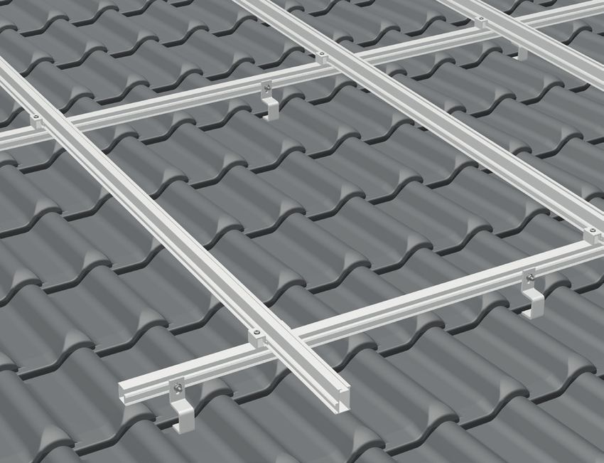
1       Introduction

1.5 Description of the system

The S:FLEX pitched roof AK offers suitable solutions for a range of different requirements:

System features of the pitched roof AK

 Application:                             Tiles, plain tiles, slates
 Module type:                             Framed modules
 Module orientation:                      Upright, transverse
 Roof inclination:                        max. 60°
 Module field length:                     max. 12.00 m connected module array
 Max. load:                               5.4 kN/m²
 Connection:                              Roof hooks
 Material:                                Aluminium EN AW-6063 T6, EN AW-6082 T6, A2 stainless steel, mild steel with
                                          corrosion protection (DIN EN ISO 12944-5 C4 long)
 Colour:                                  Natural aluminium

                 The module manufacturer's installation instructions must always be observed. All of the manufacturer's
                 specifications relating to installation on the roofing must be observed.

The roof hooks are suitable for horizontal and vertical installation of the mounting rails. Details of the various roof hooks
are provided in the sections on installation.

Height adjustment in the area of the roof battens and rails ensures a level PV field – even on uneven roof surfaces.
The system can therefore be installed on old and new buildings without any problems. The advantages of the extrusion
process are exploited for this purpose. The interlocking of grooved, optimally matched surfaces of the roof hooks and
mounting rails ensures a force-fit and form-fit connection as well as a high degree of variability.

S:FLEX GmbH • Reinbeker Weg 9 21029 Hamburg Tel. +49 (0)40 688 93 17 0 • Elsässer Str. 12 79189 Bad Krozingen Tel. +49 (0)761 888 56 08 0

info@sflex.com      www.sflex.com                                      © S:FLEX GmbH 02/2021/ Subject to technical modifications            6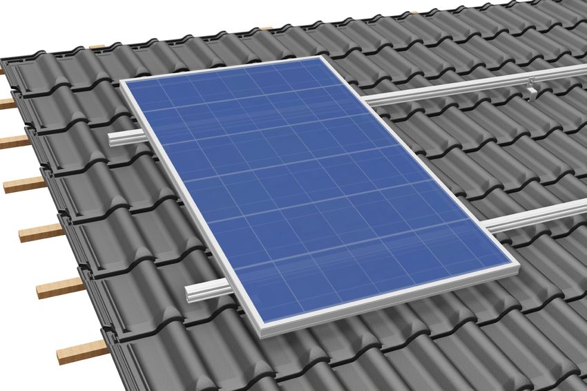
1       Introduction

Mounting rails
The S:FLEX pitched roof system is available with aluminium mounting rails of different thickness to ensure the system
corresponds
optimally to the requirements of the location and the installation situation.
The S:FLEX mounting rails feature a hammerhead slot on the side for connection to the fasteners. The mid clamps and
end clamps are mounted from above by means of click technology.

             ST-AK 5/40                ST-AK 7/47                ST-AK 13/60                 ST-AK 26/70

Rail splices

In addition to the basic installation, the splice technology allows a system orientation without a reduction in the load-
bearing capacity in the area of the splices, since they have the same static values as the associated mounting rail.

When connecting the mounting rails in succession using splices, an earthed connection can be created by applying
pressure to push the mounting rails together flush to the splices. It must be ensured that the earthed connection is
professionally inspected on site after installation.

In addition, the splice technology offers the possibility to quickly and easily create expansion joints according to the
conditions of the roof.

S:FLEX GmbH • Reinbeker Weg 9 21029 Hamburg Tel. +49 (0)40 688 93 17 0 • Elsässer Str. 12 79189 Bad Krozingen Tel. +49 (0)761 888 56 08 0

info@sflex.com      www.sflex.com                                      © S:FLEX GmbH 02/2021/ Subject to technical modifications            7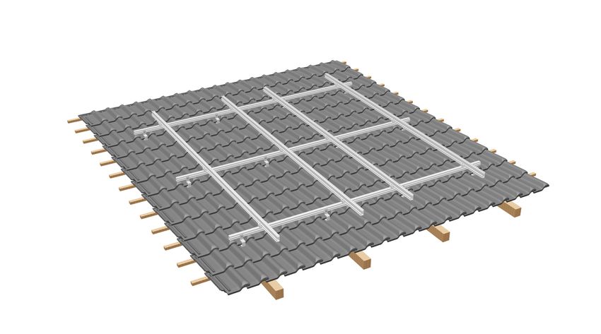
1     Introduction

Cross adapter
Intersection points (for double-layer systems) can be quickly realised in a load-bearing manner with cross adapters
with patented and proven click technology. Depending on the static requirements of the location and the installation
situation, one or two cross adapters must be arranged per intersection point.

  ST-AK 5/40               ST-AK 7/47               ST-AK 13/60             ST-AK 26/70

Module mid clamps and module end clamps
Height-adjustable module mid clamps and module end clamps with click technology allow for maximum flexibility when
installing virtually all framed module types with a frame height of 30 – 50 mm. When installing the PV modules to the
mounting rail, always comply with the installation instructions of the module manufacturer.

When performing the fastening by means of the module mid clamp and module end clamp, ensure that these clamp
onto the module frame on the clamping surface defined by the module manufacturer. Every person who installs the
S:FLEX PV fastening systems is obligated to ensure that the existing clamping surfaces correspond with the module
manufacturer's installation instructions. If the maximum clamping surfaces of the module mid clamps and module end
clamps are insufficient, it is also possible to obtain the components in different lengths.
                                                                                                                              11 mm
    Clamping range

                                                                             Clamping range

                                                                                                                      41 mm
                                  36 mm

                                           8.4 mm

                                                                                                                              11 mm

                                                       35 mm                                                                              40 mm

                                          Maximum clamping surface EC II:                                                     Maximum clamping surface MH:
          Module end clamp (EC)                                                               Module mid clamp (MC)
                                          A=8.4*35=294mm²                                                                     A=11*40=440mm² (per side)

S:FLEX GmbH • Reinbeker Weg 9 21029 Hamburg Tel. +49 (0)40 688 93 17 0 • Elsässer Str. 12 79189 Bad Krozingen Tel. +49 (0)761 888 56 08 0

info@sflex.com          www.sflex.com                                        © S:FLEX GmbH 02/2021/ Subject to technical modifications                       8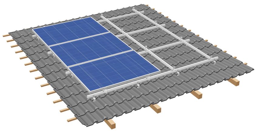
1   Introduction

Laminate clamps

The installation of frameless PV modules (laminates) is made possible by means of precisely fitting, certified laminate
end and mid clamps. These are available with our patented and proven click technology or with a hammerhead bolt.
Depending on the requirements of the laminate, different clamping ranges and lengths are available.

The suitability of the laminate end and mid clamps must be confirmed by the module manufacturer (certification). You
can obtain an overview of the respective approvals from S:FLEX.

                                                                                                                                       Clamping range
                                             37 mm

                                                     13.7 mm

                                                                             80 mm

                                                               Maximum clamping surface LEC:
   Laminate end clamp (LEC)
                                                               A=13.7*80=1096mm² (top and bottom)
                                                     13.7 mm

                                                                                                         Clamping range

                                                                                                                                       Clamping range
                                             51 mm

                                                     13.7 mm

                                                                             80 mm

   Laminate mid clamp (LMC)                                    Maximum clamping surface LMC:
                                                               A=13.7*80=1096mm² (per side, top and bottom)

S:FLEX GmbH • Reinbeker Weg 9 21029 Hamburg Tel. +49 (0)40 688 93 17 0 • Elsässer Str. 12 79189 Bad Krozingen Tel. +49 (0)761 888 56 08 0

info@sflex.com      www.sflex.com                                             © S:FLEX GmbH 02/2021/ Subject to technical modifications                 9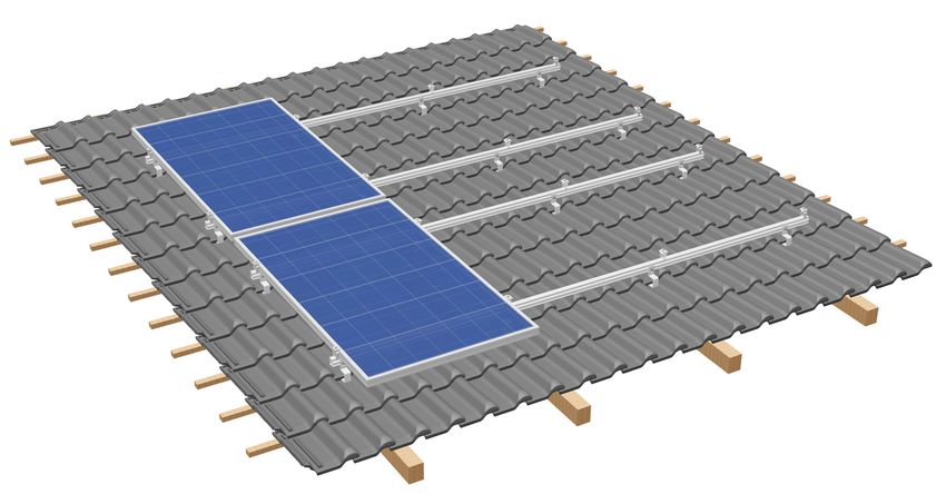
1       Introduction

Earthing

Equipotential bonding between the individual system components must be ensured in accordance with the respective
country-specific guidelines and standards. System-specific properties (see splice technology) among other things can
be used for this purpose.
This installation recommendation does not include an earthing concept and must be calculated or compiled by the
installer in accordance with the applicable standards and guidelines.

                 The earthing system is not a lightning protection system! When installing a lightning protection
                 system, a specialist company must be consulted and a project-specific lightning protection plan
                 drawn up. The module manufacturer's installation instructions must always be observed.

The earthed connection of the mounting rails is established by the splice. Additional earthing of the modules can be
achieved via the grounding plate by mounting it under the mid clamps. Before earthing the module, the corresponding
specifications issued by the module manufacturer must be followed.

     Optional items

     Covering caps

     The S:FLEX PV fastening system includes matching covering caps for the mounting rails.

S:FLEX GmbH • Reinbeker Weg 9 21029 Hamburg Tel. +49 (0)40 688 93 17 0 • Elsässer Str. 12 79189 Bad Krozingen Tel. +49 (0)761 888 56 08 0

info@sflex.com      www.sflex.com                                      © S:FLEX GmbH 02/2021/ Subject to technical modifications            10
2 Pitched roof installation AK
2.1 System components
1 Roof hooks
Roof hook Alu 93-7-45
Roof hook Hybrid Roof hook plain tile,
112-7-43 6mm Roof hook Alu 93-7-40 complete
Roof hook Hybrid Roof hook Alu 93-7-45
112-7-46 8mm complete black Roof hook slate,
complete
Roof hook Hybrid Roof hook Alu 111-9-45
149-9-43 6mm
“Biber Vario” metal roof
Roof hook Alu 111-9-40
Roof hook Hybrid plate, galvanised
149-9-46 8mm Roof hook Alu 111-9-45
complete black
Roof hook Vario Roof hook Alu 150-7-45
111-9-40
Roof hook Alu 180-9-40
2 Mounting rails
ST-AK 5/40 ST-AK 7/47 ST-AK 13/60 ST-AK 26/70
3 Splices
Splice 5 Splice 7 Splice 13 Splice 26
4 End clamp 5 Mid clamp 6 Cross adapter
EH AK II Klick 30-50 MH AK II Klick 30-50 A Cross adapter AK
EH AK II Klick 30-50 MH AK II Klick 30-50 MH AK II Klick 30-50 with
black black grounding plate
7 Covering caps
Covering cap 5 Covering cap 7 Covering cap 13 Covering cap 26
8 Slipping protection set 9 Locking clips 10 Wood screws 11 Cable clips (optional)
Slipping protection set Locking clip AK Cable clip edge
clip KC 15
S:FLEX GmbH • Reinbeker Weg 9 21029 Hamburg Tel. +49 (0)40 688 93 17 0 • Elsässer Str. 12 79189 Bad Krozingen Tel. +49 (0)761 888 56 08 0
info@sflex.com www.sflex.com © S:FLEX GmbH 02/2021/ Subject to technical modifications 112 Pitched roof installation AK
Roof connection for roofing tiles
2.2 Installing the roof hooks
2.2.1 Roof connection for roofing tiles
The majority of roof coverings consist of roofing tiles. The S:FLEX PV fastening system offers adjustable roof hooks for
connection to the existing roof covering (tile dimensions) or roof construction (tile thickness and roof batten height).
Mounting rails can be installed on the S:FLEX roof hooks. For different tile dimensions, roof hooks with suitable adapter
plates are available to ensure the necessary lateral adjustment. The roof hooks are mounted with suitable wood screws.
In the roof batten/tile area, the roof hooks are variably adjustable from 40 – 62 mm. If the adjustment range of the roof
hooks is not sufficient, the roof hooks must be fully underlaid with a pressure-resistant underlay.
The described adjustment options can be found in the description of the roof hooks.
Roof hook Alu: base plate width – hole pattern – minimum distance to rafter.
Explanation of the terms using the example of:
Roof hook Hybrid 112-7-46
Roof hook Hybrid 112-7-46
Steel
Base plate:
Aluminium Ø 7mm
46 – 61mm
112 mm
5mm 5mm
minimum
distance to = distance = distance
rafter from bracket from bracket to
to roofing tile roofing tile
= tile + batten
height
:FLEX GmbH 2017
S:FLEX GmbH • Reinbeker Weg 9 21029 Hamburg Tel. +49 (0)40 688 93 17 0 • Elsässer Str. 12 79189 Bad Krozingen Tel. +49 (0)761 888 56 08 0
info@sflex.com www.sflWerkstoff
ex.com © S:FLEX GmbH 02/2021/ Subject to technical modifications 12
Allgemeintoleranz Oberfläche Gewicht Anmerkung Allgemeintoleranz Oberfläche Werkstoff
DIN ISO 2768-1 m pressblank 0,787 kg DIN ISO 2768-1 m pressblank2 Pitched roof installation AK
Roof connection for roofing tiles
The following minimum rafter dimensions and rules apply for the installation of roof hooks and wood screws.
Standard: DIN EN 1995-1-1:2010-12 Eurocode 5 Design of timber structures
Minimum rafter Minimum rafter Minimum rafter
width 45 mm width 53 mm width 57 mm
Roof hook Hybrid 112-7-43 Roof hook Hybrid 149-9-43 Roof hook Alu 111-9-40
Roof hook Hybrid 112-7-46 Roof hook Hybrid 149-9-46 Roof hook Alu 111-9-45
Roof hook Alu 93-7-40 Roof hook Hybrid xxx-9-xx Roof hook Alu 111-9-45 complete black
Roof hook Alu 93-7-45 Roof hook Alu 180-9-40
Roof hook Alu 93-7-45 complete black Roof hook Vario 111-9-40
Roof hook Alu 150-7-45 Roof hook Alu xxx-9-xx
Roof hook Hybrid xxx-7-xx
Roof hook Alu xxx-7-xx
Roof hook Hybrid 112-7-46 Roof hook Hybrid 149-9-46
(example illustration) (example illustration)
Min. 3 screws with Min. 2 screws with
d=6mm d=8mm
Distance to
tile 5mm Distance to tile
5mm
- Two screws in the lower row of holes and - One screw in the lower row of holes and one
one screw in the upper row of holes screw in the upper row of holes
- Edge distance: Screw centre – rafter edge at - Edge distance: Screw centre – rafter edge at
least 2.5xd1 = 15mm least 3.0xd = 24mm
- all roof hooks with 7mm hole diameter: - all roof hooks with 9mm hole diameter:
3x wood screw d=6mm 2x wood screw d=8mm
- Minimum screw-in depth: 50mm - Minimum screw-in depth: 70mm
1
2.5xd only applies when using S:FLEX screws (Art. No. 700-102-68x)
In special cases, installation on rafters with a width between 36mm and 45mm is possible. This always requires
project-related planning and approval.
Observe rafter dimensions and rules for screw mounting!
S:FLEX GmbH • Reinbeker Weg 9 21029 Hamburg Tel. +49 (0)40 688 93 17 0 • Elsässer Str. 12 79189 Bad Krozingen Tel. +49 (0)761 888 56 08 0
info@sflex.com www.sflex.com © S:FLEX GmbH 02/2021/ Subject to technical modifications 132 Pitched roof installation AK
Roof connection for roofing tiles
Roof hook Vario for vertical and horizontal rail connection
90°
90°
The roof hook Vario enables module The bracket is rotated by 90° for the
horizontal rail connection. Loosen
support rails to be mounted vertically.
nut, rotate bracket and ribbed plate
In this case, the installation rules for by 90° and re-tighten nut (tightening
roofing tiles apply. torque 12–15 Nm)
Installing the roof hooks
The positioning of the roof hooks must be determined in accordance with the static requirements of the location and
the installation situation. Mark the vertical course of the rafters in chalk on the tile surface, as well as the outline of the
module array and the course of the individual module rows. Mark the position of the roof hooks according to the project
report. When doing so, it must again be checked whether the measurements used during planning match the actual
measurements found on the roof (if necessary, adjustments must be made). The position of the mounting rails must be
checked against the modules' prescribed clamping distances.
Please remove the roof tiles at the marked positions (if necessary, only push the tiles up).
Check planning basis.
Position the roof hooks
in accordance with the
static requirements and
installation situation.
Align the roof hooks
using a plumb line.
Loosen the screw on the roof hook bracket until the bracket can be moved. Position the roof hook (use a guide) and fix
it to the rafters with wood screws.
S:FLEX GmbH • Reinbeker Weg 9 21029 Hamburg Tel. +49 (0)40 688 93 17 0 • Elsässer Str. 12 79189 Bad Krozingen Tel. +49 (0)761 888 56 08 0
info@sflex.com www.sflex.com © S:FLEX GmbH 02/2021/ Subject to technical modifications 142 Pitched roof installation AK
Roof connection for roofing tiles
Next, adjust the roof hook bracket vertically and laterally until it is situated in the trough of the tile. There must be 5 mm
clearance between roof tile and bracket. Tighten the bracket with the screw (tightening torque 20–25 Nm).
5mm
= distance
from bracket to
roofing tile
Reposition the removed tiles correctly. After the installation of the roof hooks, the tiles must lie flat again to ensure
that the roof covering is watertight. In the case of roofing with interlocking tiles, the seams on the upper and lower tile
must be cut out with an angle grinder at the point where the roof hook passes through. With roof tiles (e.g. Frankfurter
Pfanne), only the upper roof tile should be cut out. In case of high snow loads, the lower tile can be replaced with a
suitable metal roof plate. Suitable metal roof plates for all common tile types are available from S:Flex.
Recess on the roofing tiles
S:FLEX GmbH • Reinbeker Weg 9 21029 Hamburg Tel. +49 (0)40 688 93 17 0 • Elsässer Str. 12 79189 Bad Krozingen Tel. +49 (0)761 888 56 08 0
info@sflex.com www.sflex.com © S:FLEX GmbH 02/2021/ Subject to technical modifications 152 Pitched roof installation AK
Roof connection for plain tiles
2.2.2 Roof connection for plain tiles
For plain-tile roofing, the S:FLEX PV fastening system includes the roof hook plain tile with metal roof tiles. The plain
tiles must be removed and then and replaced during installation.
The plain tile situated under the roof hook is replaced with a “Biber Vario” metal roof plate, so that the roof hook does
not press on the roofing. The metal roof plates are included in the S:Flex product range.
To design the connection of the S:FLEX PV fastening system on roofs covered with plain tiles, please
contact a specialist roofing company.
The plain-tile roof hooks allow the mounting rails to be installed horizontally.
Double roofing Crown-tile roofs
The installation sequences for the roof connection are described below using the example of double roofing (most
frequently encountered) with the roof hook plain tile.
The following installation recommendation for connecting the S:FLEX PV fastening system to plain-
tile roofs with double roofing serves as an example. To ensure a technically correct execution of the
connection to the roof, contact a specialist roofing company.
S:FLEX GmbH • Reinbeker Weg 9 21029 Hamburg Tel. +49 (0)40 688 93 17 0 • Elsässer Str. 12 79189 Bad Krozingen Tel. +49 (0)761 888 56 08 0
info@sflex.com www.sflex.com © S:FLEX GmbH 02/2021/ Subject to technical modifications 162.3 Pitched roof installation AK
Roof connection for plain tiles
The positioning of the roof hooks must be determined in accordance with the static requirements of the location and the
installation situation. When doing so, it must again be checked whether the measurements used during planning match
the actual measurements found on the roof (if necessary, adjustments must be made). The position of the mounting
rails must be checked against the modules' prescribed clamping distances.
Check planning basis
and remove roof tiles, if
necessary simply push
them up.
Position the roof hooks
in accordance with the
static requirements and
installation situation.
Always use metal roof
plates.
Align the roof hooks using
a plumb line
At the marked positions, remove the plain tiles and replace the plain tile under the roof hook with a metal roof plate.
Fix the metal roof plate to the roof batten with nails or suitable screws and glue the foam wedge to the upper edge.
Position the roof hook plain tile and fix it with two round head wood screws (8x80).
Re-lay the remaining plain tiles.
Install with two wood screws
Round head screws 8x80
Observe screw
arrangement and edge
distances.
S:FLEX GmbH • Reinbeker Weg 9 21029 Hamburg Tel. +49 (0)40 688 93 17 0 • Elsässer Str. 12 79189 Bad Krozingen Tel. +49 (0)761 888 56 08 0
info@sflex.com www.sflex.com © S:FLEX GmbH 02/2021/ Subject to technical modifications 172 Pitched roof installation AK
Roof connection for slates
2.2.3 Roof connection for slates
As a solution for slate roofs, the S:FLEX PV fastening system includes the roof hook slate. The installation of the roof
hook slate should take place while the roofing is being laid (new buildings). If the roofing is already installed, the slates
must be removed and, if necessary, processed (recessed) prior to installation.
As a rule, a titanium zinc sheet is attached to the formwork above the formwork liner. The sheet should overlap with the
slate roofing around the exposed area to an extent that ensures the roofing remains watertight. The roof hook slate is
mounted to the rafters above this sheet. Above the roof hook slate, an additional titanium zinc sheet is attached to the
formwork to ensure that the roofing is watertight. The titanium zinc sheet must be procured on site to ensure it matches
the existing roofing. The required sheets are not included in the S:FLEX delivery.
To design the connection of the S:FLEX PV fastening system on slate roofs, please contact a specialist
roofing company.
The slate roof hooks allow the mounting rails to be installed horizontally.
Universal roofing
The installation sequences for the roof connection are described below using the example of universal roofing with full
formwork and the roof hook slate.
The following installation instructions for connecting the S:FLEX PV fastening system to slate roofs
serves as an example. To ensure a technically correct connection to the roof, contact a specialist
roofing company.
S:FLEX GmbH • Reinbeker Weg 9 21029 Hamburg Tel. +49 (0)40 688 93 17 0 • Elsässer Str. 12 79189 Bad Krozingen Tel. +49 (0)761 888 56 08 0
info@sflex.com www.sflex.com © S:FLEX GmbH 02/2021/ Subject to technical modifications 182 Pitched roof installation AK
Roof connection for slates
The positioning of the roof hooks must be determined in accordance with the static requirements of the location and the
installation situation. When doing so, it must again be checked whether the measurements used during planning match
the actual measurements found on the roof (if necessary, adjustments must be made). The position of the mounting
rails must be checked against the modules' prescribed clamping distances. Remove the slates at the marked positions.
Check the planning basis
and remove slates if
necessary.
Position the roof hooks
in accordance with the
static requirements and
installation situation.
Align the roof hooks using
a plumb line.
Use titanium zinc sheet
and ensure it overlaps by
the correct distance.
Depending on their size, one or two slates must be replaced with a titanium zinc plate (to be provided by the customer).
This is attached to the formwork. It is important to ensure that the sheet extends under the slates at the sides and over
the slates at the bottom to ensure that the roofing is
watertight.
Position the roof hook slate (use a plumb line) and fix it to the rafters with three countersunk screws 6x80.
Install with three wood screws
Countersunk screws 6x80
Observe screw
arrangement and edge
30 distances.
S:FLEX GmbH • Reinbeker Weg 9 21029 Hamburg Tel. +49 (0)40 688 93 17 0 • Elsässer Str. 12 79189 Bad Krozingen Tel. +49 (0)761 888 56 08 0
info@sflex.com www.sflex.com © S:FLEX GmbH 02/2021/ Subject to technical modifications 192 Pitched roof installation AK
Roof connection for slates
An additional titanium zinc sheet must be installed above the roof hook. Any resulting free spaces between the titanium
zinc
sheets and adjacent slates must be sealed with sealing tape (to be provided by the customer).
The adjoining slates must be fastened in accordance with the rules and regulations of the roofing trade.
Seal free spaces with
sealing tape
If necessary, create a
recess in the roofing
tiles
Schematic diagram – due to the diversity of slate roofing types, the roof hooks should always be installed by a specialist
roofing company.
S:FLEX GmbH • Reinbeker Weg 9 21029 Hamburg Tel. +49 (0)40 688 93 17 0 • Elsässer Str. 12 79189 Bad Krozingen Tel. +49 (0)761 888 56 08 0
info@sflex.com www.sflex.com © S:FLEX GmbH 02/2021/ Subject to technical modifications 202 Pitched roof installation AK
Frame assembly, single-layer
2.3 Frame assembly
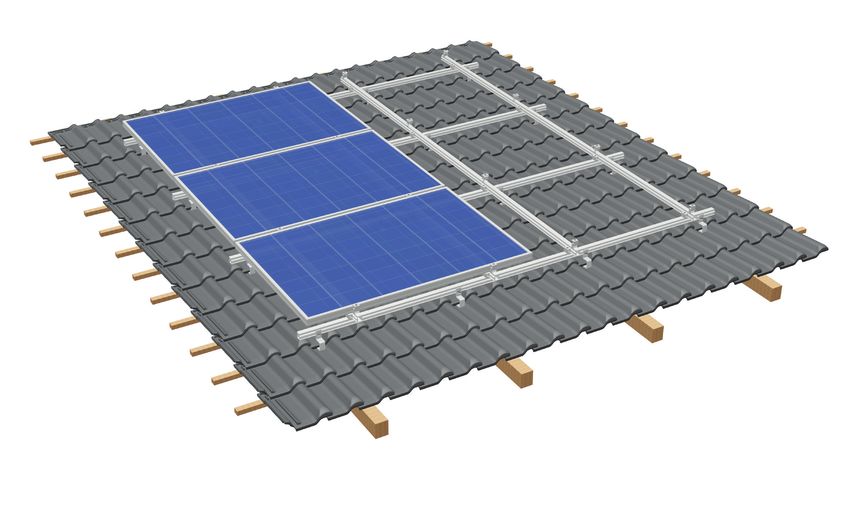
2.3.1 Single-layer assembly with framed PV modules in upright orientation
The installation instructions for "Single-layer assembly with framed PV modules in upright orientation" are only valid in
conjunction with the instructions in section 2.2. The installer must ensure that only current and complete installation
recommendations are used for the installation process.
5 Mid clamps
4 End clamp
3 Splices
2 Mounting rails
1 Roof hooks
S:FLEX GmbH • Reinbeker Weg 9 21029 Hamburg Tel. +49 (0)40 688 93 17 0 • Elsässer Str. 12 79189 Bad Krozingen Tel. +49 (0)761 888 56 08 0
info@sflex.com www.sflex.com © S:FLEX GmbH 02/2021/ Subject to technical modifications 212 Pitched roof installation AK
Frame assembly, single-layer
Attach the horizontal mounting rail (which runs parallel to the eaves) to the roof hooks using a hammerhead bolt M8x25
and self-locking nut. Make sure that the hammerhead bolts are correctly aligned in the channel of the mounting rail
(tightening torque 12–15 Nm) and that the mounting rail is not under tension. To do this, use the adjustability that is
created by the corrugation of the components and the elongated hole. Ensure that a force-fit and form-fit connection is
created by interlocking the corrugations.
Alignment of
hammerhead bolt
Force and form fit
Position of hammerhead bolt
13
Check the alignment of the
hammerhead bolts. The
hammerhead bolt is only correctly
21 mm mounted if the vertical notch is
visible.
Use the adjustability due to
corrugation and elongated hole
Create force-fit and form-fit
connection
S:FLEX GmbH • Reinbeker Weg 9 21029 Hamburg Tel. +49 (0)40 688 93 17 0 • Elsässer Str. 12 79189 Bad Krozingen Tel. +49 (0)761 888 56 08 0
info@sflex.com www.sflex.com © S:FLEX GmbH 02/2021/ Subject to technical modifications 222 Pitched roof installation AK
Frame assembly, single-layer
To join several rails together, the splice with identical static values to the mounting rail is pushed half-way into the
previously installed mounting rail. Then push the next mounting rail onto the splice. Use pressure to push the mounting
rails together flush.
The connection is then complete.
Fasten the pushed-on mounting rail to the roof hooks as described.
Push in splice
Push mounting rails together
Push in splice.
Complete
No cantilevers with splices.
Position the splices between two roof hooks.
Cantilever – incorrect! Correct!
S:FLEX GmbH • Reinbeker Weg 9 21029 Hamburg Tel. +49 (0)40 688 93 17 0 • Elsässer Str. 12 79189 Bad Krozingen Tel. +49 (0)761 888 56 08 0
info@sflex.com www.sflex.com © S:FLEX GmbH 02/2021/ Subject to technical modifications 232 Pitched roof installation AK
Frame assembly, single-layer
If the mounting rail is longer than 12.00 m, the module array must be separated by placing two
end clamps.
The mounting rail must be separated in the area between the end clamps and connected with a
splice to ensure a 2 cm compensation in length (expansion joint).
The arrangement of the expansion joints must be adapted in accordance with the structural
conditions of the roof and the expansion properties of the respective materials.
Modules must not be built over expansion joints.
There is no connection to earth.
This must be established without restricting the effect of the expansion joint.
Expansion joint
2 cm
Completed installation of the mounting-rail layer.
S:FLEX GmbH • Reinbeker Weg 9 21029 Hamburg Tel. +49 (0)40 688 93 17 0 • Elsässer Str. 12 79189 Bad Krozingen Tel. +49 (0)761 888 56 08 0
info@sflex.com www.sflex.com © S:FLEX GmbH 02/2021/ Subject to technical modifications 242 Pitched roof installation AK
Double-layer assembly
2.3.2 Double-layer assembly with framed PV modules in transverse orientation
The installation instructions for "Double-layer assembly with framed PV modules in horizontal orientation" are only valid
in conjunction with the instructions in section 2.2. The installer must ensure that only current and complete installation
recommendations are used for the installation process.
5 Mid clamps
4 End clamp
3 Splices
2 Mounting rails
6 Cross adapter
1 Roof hooks
S:FLEX GmbH • Reinbeker Weg 9 21029 Hamburg Tel. +49 (0)40 688 93 17 0 • Elsässer Str. 12 79189 Bad Krozingen Tel. +49 (0)761 888 56 08 0
info@sflex.com www.sflex.com © S:FLEX GmbH 02/2021/ Subject to technical modifications 252 Pitched roof installation AK
Double-layer assembly
The installation of the lower horizontal rail layer is carried out as shown in 2.3.1 "Single-layer installation".
Install the horizontal mounting rails for each module row on the horizontal mounting rails using the cross adapters. The
spacing between the vertical mounting rails is determined by the clamping areas, which are described in the installation
instructions. To proceed, click the cross adapter onto the horizontal mounting rail and then use it to secure the vertical
mounting rail.
Ensure that the spacing between the vertical rails corresponds to the prescribed clamping distances for the module.
The vertical mounting rails should always be assembled from bottom to top.
Ensure that the cross adapter is clicked in properly and tighten the screw (tightening torque 8–10 Nm).
Mounting the cross adapters
S:FLEX GmbH • Reinbeker Weg 9 21029 Hamburg Tel. +49 (0)40 688 93 17 0 • Elsässer Str. 12 79189 Bad Krozingen Tel. +49 (0)761 888 56 08 0
info@sflex.com www.sflex.com © S:FLEX GmbH 02/2021/ Subject to technical modifications 262 Pitched roof installation AK
Double-layer assembly
The number of cross adapters required per fixing point depends on the static requirements of the location and the
installation situation. A second cross adapter is also mounted as described above. Position it on the side of the rail
opposite the first crossbar connector (tightening torque 8–10 Nm).
Intersection points:
1x cross adapter in the side hammerhead
1x cross adapter in the channel and 1 cross adapter on the
side hammerhead channel opposite side
ST-AK 5/40 ST-AK 7/47 ST-AK 13/60 ST-AK 26/70
Specifications for the spacing between the vertical mounting rails can be found in the installation instructions.
Cross adapter in the side
hammerhead channel and on INCORRECT
opposite side
Both sides clicked in INCORRECT
S:FLEX GmbH • Reinbeker Weg 9 21029 Hamburg Tel. +49 (0)40 688 93 17 0 • Elsässer Str. 12 79189 Bad Krozingen Tel. +49 (0)761 888 56 08 0
info@sflex.com www.sflex.com © S:FLEX GmbH 02/2021/ Subject to technical modifications 272 Pitched roof installation AK
Double-layer assembly
Vertical mounting rails are arranged in lines in the same way as shown for horizontal mounting
rails.
The splices must be positioned in such a way that they lie between two mounting rail
intersection points (no cantilevers with splices). When extending the vertical mounting rails at
the lower section of the eaves, it must be ensured that the short mounting rail sections, which
are connected at the bottom, run over at least two rails in the lower layer of mounting rails.
If the mounting rail is longer than 12.00 m, the module array must be separated by placing two
end clamps.
The rail must be separated in the area between the end clamps and connected with a splice to
ensure a 2 cm compensation in length (expansion joint).
The arrangement of the expansion joints must be adapted in accordance with the structural
conditions of the roof and the expansion properties of the respective materials.
To install the end clamps, please refer to the "Module installation" section of these installation
instructions. Modules must not be built over expansion joints.
Expansion joint
2 cm
Expansion joint upper layer
Completed installation of the mounting-rail layer.
S:FLEX GmbH • Reinbeker Weg 9 21029 Hamburg Tel. +49 (0)40 688 93 17 0 • Elsässer Str. 12 79189 Bad Krozingen Tel. +49 (0)761 888 56 08 0
info@sflex.com www.sflex.com © S:FLEX GmbH 02/2021/ Subject to technical modifications 282 Pitched roof installation AK
Module installation, upright
2.4 Installing PV modules
The installation instructions provided by the module manufacturer must be observed, especially
with regard to clamping surfaces and clamping areas. S:FLEX GmbH is not liable for damage to the
modules and all other consequences resulting from non-compliance with the module manufacturer's
installation instructions.
2.4.1 Module installation, upright
Before installing the modules in the lowest row of modules, the modules generally need to be
equipped with slipping protection. The same applies to modules which do not have any modules
directly below them (modules above obstructions such as windows, chimneys, etc.).
Fix two screws M6 x 20 (with the shank downward) with nuts M6 in two of the module’s frame
holes (8 mm) so that the screws are at the same level and, when installed, they are above at least
one horizontal mounting rail layer.
If the lower mounting hole is larger than 8 mm, please use an appropriately sized (8 mm) screw.
S:FLEX GmbH • Reinbeker Weg 9 21029 Hamburg Tel. +49 (0)40 688 93 17 0 • Elsässer Str. 12 79189 Bad Krozingen Tel. +49 (0)761 888 56 08 0
info@sflex.com www.sflex.com © S:FLEX GmbH 02/2021/ Subject to technical modifications 292 Pitched roof installation AK
Module installation, upright
Module installation – (end clamps)
Place the module on the mounting rails. Install the end clamps. Click each end clamp on to the mounting rail and push it
on to the module. Ensure that the end clamp is clicked in to both sides of the mounting rail. Now adjust the end clamp
to match the height of the module and tighten the screw (torque 8–10 Nm). Pay attention to the prescribed clamping
areas and clamping surfaces.
The distance between the module frame and rail end must be at least 35 mm.
Snap in the end clamp...
Push in and tighten
Install the end clamp
Both sides clicked in INCORRECT Defined clamping area INCORRECT
Check the clamping surface defined by the
module manufacturer, follow the instructions
Check that the end clamp has been clicked in in section 1.5 (observe the module
properly manufacturer's specifications).
S:FLEX GmbH • Reinbeker Weg 9 21029 Hamburg Tel. +49 (0)40 688 93 17 0 • Elsässer Str. 12 79189 Bad Krozingen Tel. +49 (0)761 888 56 08 0
info@sflex.com www.sflex.com © S:FLEX GmbH 02/2021/ Subject to technical modifications 302 Pitched roof installation AK
Module installation, upright
Module installation – (mid clamps)
Now install the mid clamps. The grounding plate must be fitted (if required) before mounting the mid clamp. The
grounding plate is inserted laterally into the mid clamp between the "clamp" and the "upper part" (see 1.5). Next, click
each mid clamp onto the mounting rail and push it on to the module. Ensure that the mid clamp is clicked in to both
sides of the mounting rail.
Pay attention to the prescribed clamping areas and clamping surfaces. When using the grounding plate, the module
must be positioned between the plate and the "upper part" of the mid clamp. The grounding plate is thus pressed
against the mounting rail from the underside of the module frame.
Click mid clamp and push in
Align the upper row of modules with the aid of a guide or levelling instrument.
Now slide the next module underneath the mid clamp, adjust the mid clamp to the height of the module's frame and
tighten the screw (tightening torque 8–10 Nm).
Slide module underneath and
tighten mid clamp
Install mid clamp
S:FLEX GmbH • Reinbeker Weg 9 21029 Hamburg Tel. +49 (0)40 688 93 17 0 • Elsässer Str. 12 79189 Bad Krozingen Tel. +49 (0)761 888 56 08 0
info@sflex.com www.sflex.com © S:FLEX GmbH 02/2021/ Subject to technical modifications 312 Pitched roof installation AK
Module installation, upright
Ensure that the mid clamp grips both of the module frames on the clamping surface defined by the module manufacturer.
CORRECT –
INCORRECT
defined clamping area –
Mounting with grounding plate:
Check the clamping surface defined
by the module manufacturer, follow
the instructions in section 1.5
(observe the module manufacturer's
specifications).
CORRECT
INCORRECT
– defined clamping area –
Check the mid clamp has been clicked
in properly.
CORRECT
INCORRECT
– clickedin on both sides –
S:FLEX GmbH • Reinbeker Weg 9 21029 Hamburg Tel. +49 (0)40 688 93 17 0 • Elsässer Str. 12 79189 Bad Krozingen Tel. +49 (0)761 888 56 08 0
info@sflex.com www.sflex.com © S:FLEX GmbH 02/2021/ Subject to technical modifications 322 Pitched roof installation AK
Module installation, upright
Module installation – (end clamps at the end of the row)
End clamps must be installed on the last module in each row (if applicable, on expansion joints). Click each end clamp on
to the mounting rail and push it on to the module. Ensure that the end clamp is clicked in to both sides of the mounting
rail. Now adjust the end clamp to match the height of the module and tighten the screw (torque 8–10 Nm).
Pay attention to the prescribed clamping areas and clamping surfaces. Shorten projecting rails parallel to the module
frame. The distance between the module frame and rail end must be at least 35 mm.
Install end clamp on the last
module
Proceed as described for the following rows.
S:FLEX GmbH • Reinbeker Weg 9 21029 Hamburg Tel. +49 (0)40 688 93 17 0 • Elsässer Str. 12 79189 Bad Krozingen Tel. +49 (0)761 888 56 08 0
info@sflex.com www.sflex.com © S:FLEX GmbH 02/2021/ Subject to technical modifications 332 Pitched roof installation AK
Module installation, transverse
2.4.2 Module installation, transverse
Module installation – (end clamps)
Place the module on the mounting rails. Install the end clamps. Click each end clamp on to the mounting rail and push
it on to the module. Ensure that the end clamp is clicked in to both sides of the mounting rail.
Now adjust the end clamp to match the height of the module and tighten the screw (torque 8–10 Nm). Pay attention
to the prescribed clamping areas and clamping surfaces. The distance between the module frame and rail end must be
at least 35 mm.
Snap in the end clamp...
Push in and tighten
Install the end clamp
Both sides clicked in INCORRECT Defined clamping area INCORRECT
Check the clamping surface defined by the
module manufacturer, follow the instructions
Check that the end clamp has been clicked in in section 1.5 (observe module manufacturer's
properly specifications).
S:FLEX GmbH • Reinbeker Weg 9 21029 Hamburg Tel. +49 (0)40 688 93 17 0 • Elsässer Str. 12 79189 Bad Krozingen Tel. +49 (0)761 888 56 08 0
info@sflex.com www.sflex.com © S:FLEX GmbH 02/2021/ Subject to technical modifications 342 Pitched roof installation AK
Module installation, transverse
Module installation – (mid clamps)
Now install the mid clamps. The grounding plate must be fitted (if required) before mounting the mid clamp. The
grounding plate is inserted laterally into the mid clamp between the "clamp" and the "upper part" (see 1.5). Next, click
each mid clamp onto the mounting rail and push it on to the module. Ensure that the mid clamp is clicked in to both
sides of the mounting rail.
Pay attention to the prescribed clamping areas and clamping surfaces. When using the grounding plate, the module
must be positioned between the plate and the "upper part" of the mid clamp. The grounding plate is thus pressed
against the mounting rail from the underside of the module frame.
Click mid clamp and push in
Now slide the next module underneath the mid clamp, adjust the mid clamp to the height of the module's frame and
tighten the screw (tightening torque 8–10 Nm).
Slide module underneath and
tighten mid clamp
Install mid clamp
S:FLEX GmbH • Reinbeker Weg 9 21029 Hamburg Tel. +49 (0)40 688 93 17 0 • Elsässer Str. 12 79189 Bad Krozingen Tel. +49 (0)761 888 56 08 0
info@sflex.com www.sflex.com © S:FLEX GmbH 02/2021/ Subject to technical modifications 352 Pitched roof installation AK
Module installation, transverse
Ensure that the mid clamp grips both of the module frames on the clamping surface defined by the module manufacturer.
CORRECT
INCORRECT
– defined clamping area –
Mounting with grounding plate:
Check the clamping surface defined
by the module manufacturer, follow
the instructions in section 1.5
(observe the module manufacturer's
specifications).
CORRECT
INCORRECT
– defined clamping area –
Check that the mid clamp has been
clicked in properly.
CORRECT
INCORRECT
– clickedin on both sides –
S:FLEX GmbH • Reinbeker Weg 9 21029 Hamburg Tel. +49 (0)40 688 93 17 0 • Elsässer Str. 12 79189 Bad Krozingen Tel. +49 (0)761 888 56 08 0
info@sflex.com www.sflex.com © S:FLEX GmbH 02/2021/ Subject to technical modifications 362 Pitched roof installation AK
Module installation, transverse
Module installation – (end clamps at the end of the row)
End clamps must be fitted at the end of the module row and in the area of the expansion joints. Click each end clamp on
to the mounting rail and push it on to the module. Ensure that the end clamp is clicked in to both sides of the mounting
rail. Now adjust the end clamp to match the height of the module and tighten the screw (torque 8–10 Nm).
A locking clip must generally be mounted on the vertical rail below the bottom row of modules. The same applies to
modules which do not have any modules directly below them (modules above obstructions such as windows, chimneys,
etc.). The locking clip serves as an additional slipping protection. Push the locking clip onto the mounting rails from
below up to the end clamp and tighten it (tightening torque 8–10 Nm).
Pay attention to the prescribed clamping areas and clamping surfaces.
The distance between the module frame and rail end must be at least 60 mm.
Mount end clamp and locking clip
Mount an end clamp and locking
clip on the last module.
Proceed as described for the following rows.
It should be ensured here that all end clamps are secured in a horizontal line.
Align the upper row of modules with the aid of a guide or levelling instrument.
S:FLEX GmbH • Reinbeker Weg 9 21029 Hamburg Tel. +49 (0)40 688 93 17 0 • Elsässer Str. 12 79189 Bad Krozingen Tel. +49 (0)761 888 56 08 0
info@sflex.com www.sflex.com © S:FLEX GmbH 02/2021/ Subject to technical modifications 373 Disassembly and disposal
3.1 Disassembly
Disassembly of the S:FLEX mounting system may only be carried out by trained specialist personnel. Observe the same
safety instructions, standards and guidelines as provided for the installation.
In general, disassembly is carried out in reverse order to the described installation.
Before disassembly, disconnect the PV modules from the mains network.
Disconnect all of the PV modules’ electrical cables (string lines and plug connectors) and remove
them from the frame system.
Improper disassembly can lead to damage to the modules.
Remove the modules and store them safely.
Disassemble frame system and safely store all of the parts.
Check the roof surface and roof covering for damage. Any damage must be repaired professionally to prevent water
ingress and consequential damage. Any damaged tiles must be replaced, any drill holes in the sheet metal sealed, and
any openings in the roof cladding closed.
Disassemble frame system and safely store all of the parts.
Any holes in the roof must be sealed by a specialist.
3.2 Disposal
The S:FLEX mounting system is made from aluminium, stainless steel and steel components. These materials can be
recycled after disassembly.
The frame system must only be disposed of by a specialist waste management company. Observe the applicable
national standards and guidelines.
S:FLEX GmbH • Reinbeker Weg 9 21029 Hamburg Tel. +49 (0)40 688 93 17 0 • Elsässer Str. 12 79189 Bad Krozingen Tel. +49 (0)761 888 56 08 0
info@sflex.com www.sflex.com © S:FLEX GmbH 02/2021/ Subject to technical modifications 384 Terms of use and warranty 4.1 User agreement for the pitched roof system We expressly point out that the assembly system is sold under a purchase agreement. Its installation/processing or acquisition by a third party is not carried out in the name of, or on behalf of, S:FLEX GmbH. Installation/processing of the system must be carried out by appropriately qualified personnel and strictly in accordance with the installation instructions. The design and planning of the system must be undertaken using the S:FLEX Planning Software (Solar.Pro.Tool). S:FLEX GmbH is neither responsible for the project-specific structural analysis of the roof structure, nor for obtaining and documenting the approval of the roof manufacturer for use of the respective fastening system on the roof in question (in the terms of the warranty), nor for correct installation of the fastening system. S:FLEX GmbH accepts no liability for faults and damage and/or a restricted or limited operational capability of the system which has resulted from incorrect installation and/or installation which was not undertaken in accordance with the installation instructions and/or the project report (Solar.Pro.Tool). In the case of incorrect installation, the buyer's right to assert claims for material defects shall expire. The system warranty is only valid if all system components were acquired from S:FLEX GmbH. 4.2 Warranty / disclaimer The information regarding dimensioning provided in these instructions is merely suggested values based on prior experience. Binding structural analyses for installation frames can be created using the S:FLEX planning software (Solar. Pro.Tool). As an installation company, you are responsible for the correct execution of the installation. S:FLEX GmbH is not liable for the dimensional information contained in commercial system quotations. As the installation company, you are responsible for the mechanical durability of the installed interface connections on the building envelope, in particular also for their watertightness. The components supplied by the company S:FLEX GmbH are designed for the expected loads and in accordance with the currently available technology. In this context, you must provide the company S:FLEX GmbH with information about all general technical conditions in writing via the project data collection sheet (information about the supporting structure, snow load zone, building heights, wind loads, etc.). S:FLEX GmbH is not liable if the installed components are not properly handled. Any use close to the sea needs to be clarified with S:FLEX GmbH directly on a case-by-case basis due to the increased risk of corrosion. Provided that the system is handled properly and dimensioned according to the structural conditions and normal environmental and ambient conditions, the company S:FLEX GmbH provides a warranty from transfer of risk to the warranty holder, which guarantees that the metallic components of the racks will remain free from defects with regard to material and workmanship for a period of 10 years. This warranty does not apply to wear parts. For additional information, please refer to the separate warranty provisions. This applies within the context of the generally prevalent weather and environmental conditions. S:FLEX GmbH • Reinbeker Weg 9 21029 Hamburg Tel. +49 (0)40 688 93 17 0 • Elsässer Str. 12 79189 Bad Krozingen Tel. +49 (0)761 888 56 08 0 info@sflex.com www.sflex.com © S:FLEX GmbH 02/2021/ Subject to technical modifications 39
You can also read