Plasma Assisted Reduction of Graphene Oxide Films

Page created by Raul Banks
 
CONTINUE READING
Plasma Assisted Reduction of Graphene Oxide Films
nanomaterials

Review
Plasma Assisted Reduction of Graphene Oxide Films
Sri Hari Bharath Vinoth Kumar *, Ruslan Muydinov and Bernd Szyszka

                                          Institute of High-Frequency and Semiconductor System Technologies, Technische Universität Berlin, HFT 5-2,
                                          Einsteinufer 25, 10587 Berlin, Germany; ruslan.muydinov@tu-berlin.de (R.M.); bernd.szyszka@tu-berlin.de (B.S.)
                                          * Correspondence: s.vinothkumar@campus.tu-berlin.de

                                          Abstract: The past decade has seen enormous efforts in the investigation and development of reduced
                                          graphene oxide (GO) and its applications. Reduced graphene oxide (rGO) derived from GO is known
                                          to have relatively inferior electronic characteristics when compared to pristine graphene. Yet, it has its
                                          significance attributed to high-yield production from inexpensive graphite, ease of fabrication with
                                          solution processing, and thus a high potential for large-scale applications and commercialization.
                                          Amongst several available approaches for GO reduction, the mature use of plasma technologies
                                          is noteworthy. Plasma technologies credited with unique merits are well established in the field
                                          of nanotechnology and find applications across several fields. The use of plasma techniques for
                                          GO development could speed up the pathway to commercialization. In this report, we review the
                                          state-of-the-art status of plasma techniques used for the reduction of GO-films. The strength of
                                          various techniques is highlighted with a summary of the main findings in the literature. An analysis
                                          is included through the prism of chemistry and plasma physics.

                                          Keywords: graphene oxide; plasma treatment; reduction


Citation: Vinoth Kumar, S.H.B.;
                                          1. Introduction
Muydinov, R.; Szyszka, B. Plasma                The term “graphene” was coined by Boehm et al. in 1985, which refers to a two-
Assisted Reduction of Graphene            dimensional single layer of carbon atoms in a honeycomb lattice [1]. A. Geim and K.
Oxide Films. Nanomaterials 2021, 11,      Novoselov exfoliated graphene for the first time in the year 2004, which consequently
382. https://doi.org/10.3390/             earned them a Physics Nobel prize in 2010. Even before its discovery and eventually gaining
nano11020382                              the “wonder material” nickname [2], graphene was known to scientists and used in theo-
                                          retical studies dating back to 1947 [3–9]. Following the discovery, graphene has gained a lot
Academic Editor: Guqiao Ding              of attention from the scientific community across various disciplines (Figure 1a). This can
Received: 8 January 2021                  be credited to its remarkable electrical, optical, thermal, and mechanical properties [9–11].
Accepted: 28 January 2021
                                          Additionally, it possesses complete non-permeability to all standard gases [12] and the
Published: 3 February 2021
                                          ability to be chemically functionalized [13,14].
                                                Figure 1b presents schematic illustrations of the common production methods of
Publisher’s Note: MDPI stays neutral
                                          graphene. A detailed account of various production and processing techniques of graphene
with regard to jurisdictional claims in
                                          and related materials can be found in the literature [15–18]. Methods such as mechanical
published maps and institutional affil-
                                          exfoliation [19,20], epitaxial synthesis [20,21], and bottom-up synthesis from structurally
iations.
                                          defined organic precursors [20] restrict the use of graphene to fundamental research and
                                          niche applications, owing to limited scalability and high production costs. Graphene layers
                                          can be also obtained by chemical vapor deposition (CVD), a well-established technique in
                                          the industry [22,23]. The downside to this technique is that it requires suitable substrates
Copyright: © 2021 by the authors.
                                          (which are limited), a high temperature, and vacuum environment. Additionally, it involves
Licensee MDPI, Basel, Switzerland.
                                          the laborious transfer of the grown layers onto desired application substrates [23]. In liquid-
This article is an open access article
                                          phase exfoliation (LPE), pristine or expanded graphite particles (thermally expanded
distributed under the terms and
                                          graphite intercalation compounds) are first dispersed in a solvent to weaken van der Waals
conditions of the Creative Commons
                                          attraction between the graphene layers. High-quality graphene sheets are then obtained by
Attribution (CC BY) license (https://
                                          following ultrasonication [24], electric field [25], shearing [26], and microfluidization [27]
creativecommons.org/licenses/by/
4.0/).
                                          to induce exfoliation of graphite layers. Chemical additives (surfactants) are often needed

Nanomaterials 2021, 11, 382. https://doi.org/10.3390/nano11020382                                      https://www.mdpi.com/journal/nanomaterials
Plasma Assisted Reduction of Graphene Oxide Films
Nanomaterials 2021, 11, x FOR PEER REVIEW                                                                                                      2 of 38
Nanomaterials 2021, 11, 382                                                                                                                   2 of 37

                                   and microfluidization [27] to induce exfoliation of graphite layers. Chemical additives
                                 to(surfactants)
                                     keep the suspensions    stable for
                                                  are often needed       a longthe
                                                                     to keep     period,  and thestable
                                                                                   suspensions    removal
                                                                                                        for of solvent
                                                                                                            a long     mayand
                                                                                                                   period,  causethe
                                 restacking
                                   removal ofofsolvent
                                                 the graphene  platelets
                                                        may cause        due to van
                                                                    restacking        dergraphene
                                                                                 of the   Waal’s forces [17].due
                                                                                                   platelets  Some
                                                                                                                 to solvents, such
                                                                                                                    van der Waal’s
                                 as the N-methyl-pyrrolidone (NMP), are toxic and expensive with a high boiling point
                                   forces [17]. Some solvents, such as the N‐methyl‐pyrrolidone (NMP), are toxic and expen‐
                                 mandating special treatment and handling [28].
                                   sive with a high boiling point mandating special treatment and handling [28].

                                   Figure1.1. (a)
                                 Figure        (a) The
                                                   The yearly
                                                         yearly number
                                                                 numberof   ofpublications
                                                                               publicationsrelated
                                                                                               relatedtotographene
                                                                                                            graphene topic  (left‐side
                                                                                                                        topic          axis).
                                                                                                                               (left-side     DataData
                                                                                                                                          axis).    ex‐
                                   tracted  from   the  Web   of Science
                                 extracted from the Web of Science
                                                                          TM (Clarivate Analytics), searched with the “graphene” keyword in
                                                                           TM  (Clarivate Analytics), searched with the “graphene” keyword
                                   the “topic” field (date of retrieval: September 14, 2020). Yearly accumulated graphene‐related pa‐
                                 in the “topic” field (date of retrieval: September 14, 2020). Yearly accumulated graphene-related
                                   tents (right‐side axis), data extracted from [29]. (b) Schematic illustration of some of the main gra‐
                                 patents (right-side axis), data extracted from [29]. (b) Schematic illustration of some of the main
                                   phene production techniques represented in terms of yield and quality. The evaluation of the tech‐
                                 graphene     productionprocess
                                   nique’s production        techniques    represented
                                                                    is represented    in ainpentagon
                                                                                             terms of with
                                                                                                        yieldgraphene
                                                                                                               and quality.    The evaluation
                                                                                                                          crystallinity          of the
                                                                                                                                        (G), purity
                                 technique’s    production     process  is represented   in  a pentagon    with  graphene    crystallinity
                                   (P), layer number controllability (L), cost (C, a low value is related to the high cost of production), (G), purity
                                 (P),
                                   andlayer  number
                                         scalability    controllability
                                                     (S). Numbers 1, 2,(L), andcost (C, a low
                                                                                 3 indicate     value
                                                                                              low,     is related
                                                                                                   medium,     andto  the high
                                                                                                                    high,        cost of production),
                                                                                                                           respectively.  Reproduced
                                   from   Chen   et al. [30] with  permission    from  The   Royal  Society   of Chemistry.
                                 and scalability (S). Numbers 1, 2, and 3 indicate low, medium, and high, respectively. Reproduced
                                 from Chen et al. [30] with permission from The Royal Society of Chemistry.
                                       Compared to other techniques, the reduction techniques of GO yield relatively lower
                                      Compared
                                  product  qualitytobut
                                                    other techniques,
                                                        provide  some the  reductioncharacteristics.
                                                                        interesting  techniques of GO yield itself relatively
                                                                                                                    is highly lower
                                                                                                                              hydro‐
                                 product
                                  philic and can form stable monolayers in aqueous colloids [31,32]. GO andhydrophilic
                                         quality but  provide some  interesting characteristics. GO  itself  is highly   rGO can be
                                 and can form functionalized
                                  chemically   stable monolayers  in aqueous
                                                               through        colloids
                                                                         covalent  and[31,32].   GO andbonds
                                                                                        non‐covalent     rGO can   to be chemically
                                                                                                                       enhance  their
                                 functionalized through covalent and non-covalent bonds to enhance their properties and
Plasma Assisted Reduction of Graphene Oxide Films
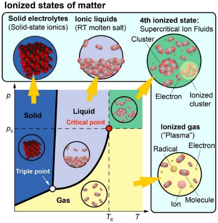
Nanomaterials 2021, 11, 382                                                                                            3 of 37

                              functionalities. In the non-covalent approach, they can be modified with metals, metal
                              oxides, and polymers through non-covalent interactions like van der Waal’s forces, π–π
                              stacking, hydrogen bonding, hydrophobic interactions, and ionic crosslinking [33]. In
                              applications such as sensors, energy storage, electrochemical systems, catalysis, etc., the
                              superior properties arise from the reactivity of the intrinsic defects and dangling bonds in
                              GO [34].
                                   Numerous review-articles on synthesis, structure and properties, fabrication tech-
                              niques, chemical modifications, and applications of GO are available [13,16,35–41]. On
                              the reduction front, specific methods (such as chemical, thermal, eco-friendly, microwave
                              methods, etc.), as well as an overview of several reduction approaches have been exam-
                              ined [42–54]. Amongst these, some reviews have only outlined the plasma method along
                              with other techniques [49,51]. The use of plasma for GO modification and functionaliza-
                              tion also has been reported [14,55]. This article aims to review the application of plasma
                              exclusively from the perspective of GO reduction, presenting an up-to-date analysis. The
                              primary objective here is to elucidate the reduction of GO-films with various plasma and
                              to highlight the potential of plasma technologies in this topic. GO in the form of mono-
                              layers, thin-films, and paper (a few µm-thick interlocked layered-structure consisting of
                              micrometer-sized graphene crystals [56,57]) is covered here apart from GO-composites [58]
                              and powders [59,60]. The fundamentals, principles, configurations, and applications of
                              plasma are not covered, as they are available in literatures [61–67]. A table is included in
                              the Appendix A (Table A1) with a non-exhaustive list of relevant publications for easy ref-
                              erencing. It incorporates various plasma generation techniques and active gases employed,
                              briefing the important experimental parameters, application, and results.

                              2. GO/rGO: Properties, Reduction Methods, and Characterization
                                   In this chapter, the structure, properties, and applications of GO/rGO are briefly
                              discussed first. It is then followed by a short overview of common reduction techniques
                              highlighting the advantages of plasma methods. Finally, the basic characterization tech-
                              niques needed to evaluate the reduction degree in rGO-films are introduced.

                              2.1. Structure and Properties of GO/rGO
                                    GO is strictly a single-layered material that is obtained by exfoliation of oxidized
                              graphite [68]. Oxidized graphite depicts a berthollide layered solid produced by treating
                              graphite with strong oxidants where the graphite surface and edges undergo covalent
                              chemical oxidation [68]. This technique dates back to 1859 when the chemist Benjamin
                              Brodie performed a similar treatment to elucidate the structure of graphite oxide [69]. As a
                              result of chemical exfoliation, GO incorporates many oxygen-containing functional groups
                              where domains of sp2 - and sp3 -hybridized carbon atoms exist [70].
                                    Until today, some ambiguity persists on the precise chemical structure of GO, and
                              several different models describe the same [52,71,72]. The most widely accepted model is
                              the one proposed in 1996 by Lerf and Klinowski (LK) [73,74], originally describing graphite
                              oxide. In the past two decades, various researchers have claimed additional structural
                              changes [75,76]. In a recent review, Brisebois et al. [76] presented a representative structure
                              of GO based on historic and modern models including recently suggested adjustments
                              in the literature (Figure 2a). As shown in Figure 2a, features A–E account for the LK
                              model. The monolayer surface gets its nearly flat carbon-grid from double bonds (A),
                              aromatic entities (B), and epoxide groups (C). Hydroxyl group-containing carbon results in
                              wrinkling of the monolayer. A large number of oxygen-containing groups (C, D, D’, and
                              D”) lie above and below the carbon-grid. Hydroxyl groups (D’) and carboxylic groups (E)
                              terminate the structure of GO. Features such as F, G, H, and I are aspects of the Dékány
                              model [76]. According to Brisebois et al. [76], the complete chemistry of GO is not yet fully
                              understood, and the general LK model should be updated with recently made observations
                              such as carbon vacancies (M), sulfate esters (N), carbon radicals (O), 1,3 butadiene systems
                              (P), and C–H bonds (Q).
Plasma Assisted Reduction of Graphene Oxide Films
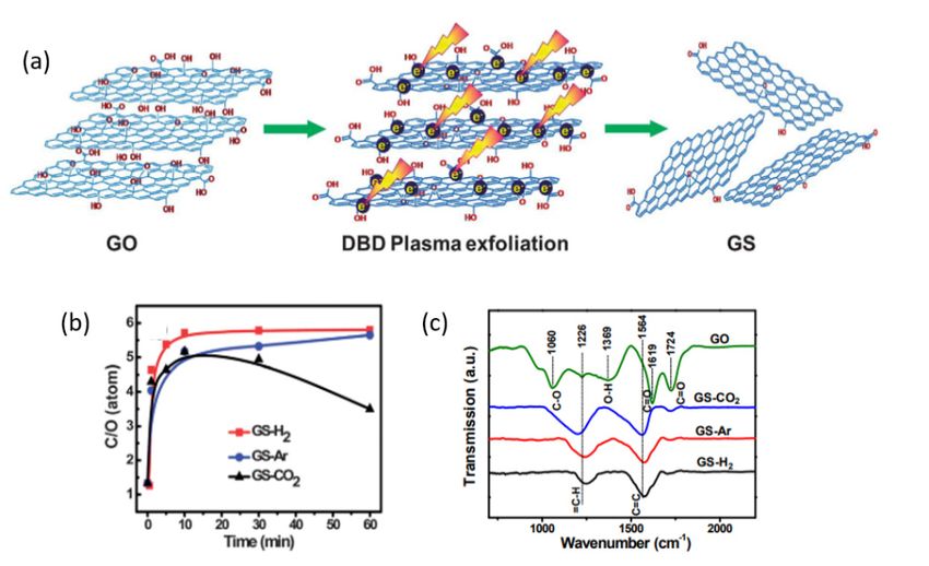
Nanomaterials 2021, 11, x FOR PEER REVIEW                                                                                                4 of 38

Nanomaterials 2021, 11, 382      understood, and the general LK model should be updated with recently made observa‐                         4 of 37
                                 tions such as carbon vacancies (M), sulfate esters (N), carbon radicals (O), 1,3 butadiene
                                 systems (P), and C–H bonds (Q).
                                      The mainly present oxygen‐functional groups in GO are epoxides (C‐O‐C), hydroxyls
                                      The
                                 (‐OH),     mainly present
                                         carboxylic     (‐COOH), oxygen-functional
                                                                      and ketone (C=O)    groups
                                                                                               onesin [77].
                                                                                                       GO are
                                                                                                            Theepoxides
                                                                                                                  presence(C-O-C),
                                                                                                                             of polarhydroxyls
                                                                                                                                        groups
                                 makes GO hydrophilic and facilitates its exfoliation in aqueous media [78].ofThe
                                 (-OH),  carboxylic      (-COOH),      and    ketone    (C=O)   ones   [77].  The  presence        polar  groups
                                                                                                                                      incorpo‐
                                 makes   GO    hydrophilic     and   facilitates    its exfoliation   in  aqueous   media
                                 rated functional groups cause an increased interlayer distance of >0.625 nm in GO from      [78].  The  incorpo-
                                 rated nm
                                 0.335  functional    groups
                                             in graphite         cause
                                                            [79,80].  GO  anhas
                                                                              increased    interlayerchemical
                                                                                  a heterogeneous        distance and
                                                                                                                   of >0.625    nm in
                                                                                                                        electronic      GO from
                                                                                                                                     structure,
                                 0.335  nm   in  graphite    [79,80].   GO    has  a  heterogeneous      chemical   and
                                 and the presence of oxygen‐containing groups make it an insulator [35,81]. The sp2 net‐  electronic   structure,
                                 and the
                                 work   of presence
                                           carbon atoms,of oxygen-containing
                                                              and thus the electrical groups    make it an can
                                                                                             conductivity,    insulator  [35,81]. The
                                                                                                                   be substantially       sp2 net-
                                                                                                                                       restored
                                 work   of carbon
                                 by various         atoms,strategies.
                                               reduction      and thus Figure
                                                                           the electrical   conductivity,
                                                                                    2b presents              can be substantially
                                                                                                  high‐resolution     imaging of rGO restored
                                                                                                                                           mon‐by
                                 various  reduction     strategies.   Figure    2b presents    high-resolution    imaging
                                 olayer reduced with H2‐plasma [82]. A large portion of crystallized graphene regions with  of  rGO   monolayer
                                 reduced with
                                 hexagonal         H2 -plasma
                                              lattice             [82].isAobserved.
                                                       (light gray)         large portionThe of crystallized
                                                                                              average          grapheneregions
                                                                                                         graphene‐like     regionshere
                                                                                                                                     withrange
                                                                                                                                           hexag-
                                 onal  lattice  (light  gray)   is observed.     The    average   graphene-like     regions
                                 from 3–6 nm covering 60% of the surface. Carbonaceous adsorbates and trapped contam‐          here  range   from
                                 3–6 nm   covering     60%   of  the surface.    Carbonaceous       adsorbates    and  trapped
                                 inants are also observed (dark gray). Other visible features include topological defects          contaminants
                                 are also
                                 (blue  andobserved     (dark gray).
                                             green), individual          Other visible
                                                                     ad‐atoms              features include
                                                                                  or substitutions              topological
                                                                                                       (red), and             defectsSuch
                                                                                                                   holes (yellow).     (bluehet‐
                                                                                                                                              and
                                 green), individual
                                 erogeneous     structuread-atoms    or substitutions
                                                             gives rise    to properties(red),
                                                                                             that and
                                                                                                  are holes    (yellow).
                                                                                                        different         Such heterogeneous
                                                                                                                   from pristine     graphene.
                                 structure
                                 Some        gives
                                        of the      rise to properties
                                                 important    properties of   that  are different
                                                                                 GO/rGO             from pristine
                                                                                             are summarized           graphene.
                                                                                                                  against           Some of in
                                                                                                                           CVD‐graphene        the
                                 important
                                 Table 1.     properties    of  GO/rGO        are summarized       against   CVD-graphene        in Table  1.

                                 Figure 2.
                                         2. (a)
                                            (a) A
                                                A historical
                                                   historicalstructural
                                                              structuralaccount
                                                                         accountofofaaGO‐flake
                                                                                       GO-flakewith
                                                                                                  withC/O
                                                                                                       C/O  atomic
                                                                                                              atomicratio ofof
                                                                                                                      ratio ~2.~2.
                                                                                                                                 Reproduced
                                                                                                                                   Reproduced
                                 from Brisebois et al. [76]
                                                        [76] with
                                                             with permission
                                                                  permission from
                                                                               from The
                                                                                     TheRoyal
                                                                                         RoyalSociety
                                                                                                Societyof ofChemistry.
                                                                                                             Chemistry.TheTheatomic
                                                                                                                               atomicresolution,
                                                                                                                                       resolu‐
                                 tion, aberration‐corrected    TEM  image  of an H 2‐plasma reduced monolayer GO: (b) Original image
                                 aberration-corrected TEM image of an H2 -plasma reduced monolayer GO: (b) Original image and
                                 and (c) with colors highlighting different features. Light gray: defect‐free crystalline graphene
                                 (c) with colors highlighting different features. Light gray: defect-free crystalline graphene area.
                                 area. Dark gray: contaminated regions. Blue: disordered single‐layer carbon network, or extended
                                 Dark gray: contaminated regions. Blue: disordered single-layer carbon network, or extended
                                 topological defects, suggested as remnants of the oxidation‐reduction process. Red: individual ad‐
                                 topological
                                 atoms          defects, suggested
                                        or substitutions.            as remnants
                                                           Green: isolated          of the
                                                                            topological    oxidation-reduction
                                                                                         defects,                   process.
                                                                                                  that is, single bond         Red:orindividual
                                                                                                                        rotations     disloca‐
                                 ad-atoms
                                 tions cores.orYellow:
                                                 substitutions.
                                                        holes andGreen:   isolated
                                                                   their edge       topologicalReproduced
                                                                              reconstructions.    defects, thatfrom
                                                                                                                 is, single bond rotations
                                                                                                                     Gomez‐Navarro      et al. or
                                 dislocations
                                 [82]. Copyrightcores. Yellow:
                                                   © 2010,       holes Chemical
                                                            American   and their Society.
                                                                                  edge reconstructions. Reprinted with permission from
                                 Gomez-Navarro et al. [82]. Copyright © 2010, American Chemical Society.
Plasma Assisted Reduction of Graphene Oxide Films
Nanomaterials 2021, 11, 382                                                                                                                    5 of 37

                                   Table 1. Summary of physical properties of monolayer CVD-graphene, various-GO, and various-rGO.
                                   Properties listed are atomic C/O ratio (RC/O ), optical transmittance (T) at 550 nm for monolayers,
                                   electrical conductivity (σ), bandgap (Eg ), thermal conductivity (κ) at room-temperature, in-plane
                                   Young’s modulus (E), and intrinsic strength (τc ).

                                            Property                CVD-Graphene                   Various-GO                  Various-rGO
                                              RC/O                          -                   0.6–2.38[47,83,84]        1.48–12 [52,85,86] *
                                        T (%, @ 550 nm)                 97.7 [87]                   >97.5 [88]               ~97.5 [88,89]
                                            σ (S/cm)                  ~104 [90,91]                          ~10−3 –103 [92,93] †
                                             Eg (eV)                        0                                  0–3.5 [94,95] †
                                           κ (W/m·K)                300–5300 [96,97]            8.8–625 [98,99] †,‡        46–2600 [100,101]
                                             E (GPa)                   1000 [102]                            290–430 [103] †,‡
                                            τc (GPa)                   130 [102]                               28–48 [103] †,‡
                                   * a wide range of RC/O have been reported for rGO [51], in certain cases exceeding >100 [104,105]. † range obtained
                                   as a function of oxidation/reduction degree. ‡ theoretical studies.

                                         The opportunity for tailoring the optoelectronic properties of GO arises from the abil-
                                   ity to manipulate its shape, size, and the fraction of sp2 /sp3 hybridized carbon domains by
                                   controlled reduction [35,106]. Finally, GO and r-GO serve as a tunable platform for several
                                   applications. Table 2 summarizes some of the features and properties of GO/rGO exploited
                                   in a wide range of science and technology topics. In optoelectronics, under the field of solar-
                                   cells alone, rGO has contributed to the progress of perovskite, perovskite-silicon tandem,
                                   dye-sensitized, and organic technologies [107–109]. Graphene materials have not been
                                   widely utilized for CIGSe as in the case of other solar cell technologies. Nevertheless, CVD–
                                   graphene has been incorporated into CIGSe, which includes a demonstration of flexible
                                   solar cell [110–112]. It is emphasized that GO/rGO can serve as hole-selective contacts and
                                   intermediate tunnel junction layer in monolithic CIGSe–Perovskite tandem solar cell appli-
                                   cations, which is yet to be reported [113]. Factors such as precursor material-form (powder,
                                   dispersion, films, paper, etc.), quality, properties, and application of rGO can influence the
                                   choice of reduction method adopted, which is discussed in the following section.

                Table 2. A summary of some of the properties and features of GO/rGO with their relevant applications.

                          Features/Properties                                         Applications/Technologies                        Reference
 Large specific area; lightweight; high conductivity; hetero-atom
                                                                          Electrochemical storage (batteries and capacitors)            [16,114]
    doping; micro-structuring; composite material formation
                                                                             Electrocatalysts for electrochemical energy
   Large specific area; tunable electronic structure; hetero-atom
                                                                           conversion reactions (water splitting; CO2 , N2 ,              [115]
      doping; structural modification and functionalization
                                                                                     and O2 reduction reaction)
  Nanocapillaries; ease of making atomically thin layers; good                Membranes (selective ion-, vapor-, gas-,
                                                                                                                                          [116]
                       mechanical properties                               water-transport; proton exchange; desalination)
      Biocompatibility; functionalization; physiochemical
                                                                             Pharmaceutical, biomedical, and biosensing                 [106,117]
                      properties; fluorescence
      Tunable electronic properties; optical transparency;
                                                                               Flexible-, thin-film, and opto-electronics               [106,118]
                       mechanical flexibility
   Non-linear optics (saturable absorption; reverse saturable
                                                                             Mode-locking; Q-switching; optical limiters                  [106]
               absorption; two-photon absorption)
 Seebeck coefficient; electrical conductivity; thermal conductivity                  Thermoelectric devices                               [106]
                                                                          Mechanical and rheological (cement composites;
  Advanced mechanical and structural properties in composites                 green plastics; composites for military                     [118]
                                                                                          and aerospace)

                                   2.2. Reduction Methods for GO
                                        Table 3 lists and summarizes commonly employed reduction methods and some
                                   of their important features along with those of the plasma method. Generally, the re-
                                   duction strategies use either a reductant (chemical, microbial, solvothermal) and/or a
Plasma Assisted Reduction of Graphene Oxide Films
Nanomaterials 2021, 11, 382                                                                                                6 of 37

                                   thermal, electrical (voltage-induced), radiative (photocatalytic, microwave, plasma), and
                                   electrochemical impact [49,119]. Chemical reagents are either used in liquid- or gas-phase
                                   for reduction [32,120]. Typically used reagents are fairly hazardous: hydrazine [94], hy-
                                   drazine hydrate [121], sodium borohydride [122], sodium hydrosulfite [122], and hydro-
                                   halic acids [121]. Hydrazine is known to be one of the most powerful reducing agents.
                                   However, high toxicity and environmental hazard make it unpopular [123]. By comparing
                                   various reducing agents, a study suggested that a reducing agent in combination with acid
                                   is beneficial in terms of preserving the rGO surface quality [124]. The processing time in
                                   the chemical techniques is relatively longer. In certain cases, the reduction process can
                                   consume a day to a week’s time [94,120].

                     Table 3. An overview of the common reduction methods with some of their important features.

      Reduction Method                                           Features                                    Reference
                                  simple and scalable approach; commonly used reducing agents are
            Chemical              toxic/hazardous; rGO yields have lower surface area and electrical          [94,125]
                                  conductivity; prolonged reduction duration
                                  simple approach; defects are created in the lattice with the removal
            Thermal               of carbon; high-temperature process not for suitable sensitive              [125,126]
                                  substrates; substantial energy consumption
                                  rGO yields have good structural quality and electrical conductivity;
        Electrochemical                                                                                            [125]
                                  non-hazardous process, large-scale production is challenging
                                  microwave absorption depends on the oxidation degree of GO;
      Microwave-assisted          reducing atmosphere are needed to improve quality of yield; high          [50,127–129]
                                  temperatures attained limit substrate selection
                                  requires special equipment; versatile and offers industrial-level
             Plasma
                                  scalability; relatively short reaction period; effective in restoration    [49,93,130]
                                  of lattice defects

                                         The solvothermal method can yield a stable dispersion of r-GO without the use of
                                   additional reductants [131]. However, the C/O atomic ratio and electrical conductivity
                                   obtained are inferior to the chemical methods [42,52]. Microbes such as Shewanella [132],
                                   E. coli [133], yeast [134], and Azotobacter chroococcum [135] can also reduce GO in the forms
                                   of dispersion or film. Though such biological agents are attractive with low-negative
                                   environmental impact, they are limited in terms of the need for sensitive culture procedure
                                   and prolonged reaction time [49].
                                         High-temperature annealing (up to 1100 ◦ C) aids the removal of oxygenated groups
                                   and significantly improves the conductivity of GO-films [136]. This approach is not appli-
                                   cable for temperature-sensitive substrates, like glass or flexible ones. When the preheating
                                   and cooling of chambers with active/inert gases or vacuum environment are considered,
                                   a substantial amount of energy is consumed, leading to poor energy efficiency. Another
                                   significant drawback of the thermal method is the creation of carbon vacancies and other
                                   structural defects in the GO plane due to the active diffusion of epoxide groups already at
                                   200 ◦ C [137,138]. Thermogravimetric analysis reveals up to ~70% final mass loss caused
                                   by the release of CO and CO2 gases [137]. The photocatalytic reduction of GO heavily
                                   relies on the presence of photoactive materials under UV radiation. This makes it suitable
                                   only for hybrid nanocomposites [46]. Electrochemical reduction offers a faster, and safer
                                   route compared to the previously noticed methods. However, it is not viable for large-scale
                                   production, and its degree of reduction is incomparably lower than in the case of the
                                   chemical or thermal method [139].
                                         Microwave-assisted reduction of GO can be realized by three routes: (i) chemical
                                   reduction, (ii) thermal reduction, and (iii) simultaneous exfoliation and reduction [127].
                                   Microwaves are effectively absorbed by π-electrons that cause very rapid warming of
                                   GO (several hundreds of degrees in few seconds) that results in the breaking of weakest
Plasma Assisted Reduction of Graphene Oxide Films
Nanomaterials 2021, 11, 382                                                                                             7 of 37

                              bonds [127]. According to this principle, r-GO domains with sp2 carbon network and free
                              π-electrons heat faster than GO-ones that minimize the efficiency of this method [128,129].
                              When chemically reduced or simultaneously exfoliated and reduced, the quality of r-GO is
                              low and oxygen content is as high as in the case of the conventional thermal method [54,127].
                              Laser irradiation can also induce local heating in light-absorbing domains of GO and thus
                              be utilized for reduction. The local temperatures can reach 1400 K in this case [140]. In the
                              case of GO films the heat absorbed dissipates to underlying layers and substrate, yielding
                              additional issues. The photothermal reduction (such as the laser and flash techniques) can
                              provide moderate to high atomic C/O ratio (~10 and ~15, respectively) but creates pores,
                              cracks, and voids in GO-films, which could limit its applications [141].
                                    Compared to the previously discussed methods, plasma-assisted reduction techniques
                              are much more attractive for films due to the following reasons. Plasma processes are
                              established and well-controlled, which offers ease of operation also on the industrial scale.
                              Despite relatively expensive equipment, the versatility of plasma processes today forms a
                              vital part of production in various technological fields [67]. Different power generation
                              techniques extended by a wide range of operating pressures including the atmospheric one,
                              as well as the applicability of various active gases, make this approach multidimensional.
                              It opens the way to control the energy of the acting species and tune the chemical footprint
                              of plasma. Moreover, the thermal impact of plasma and the depth of penetrating damage
                              can be also restricted. For attaining graphene-like properties in rGO, significant restoration
                              of the graphitic structure by defect repair is essential. Amongst the available techniques
                              to realize this, the plasma method is one of them, others being the thermally assisted
                              CVD method (>1073 K) and sequential chemical reduction followed by high-temperature
                              graphitization (~2073 K) [48,142]. From environmental, health, and safety aspects, plasma
                              technology has remarkable advantages over chemical and thermal processes [143]. Owing
                              to their advantages, plasmas have demonstrated their attractiveness in the synthesis of
                              graphene and related materials [130,144–146].

                              2.3. Characterization of rGO
                                     The effectiveness of GO reduction is widely assessed based on (i) surface atomic
                              carbon/oxygen ratio (RC/O ) and (ii) electrical properties: hole/electron mobility (µ), sheet
                              resistance (RSH ), and conductivity (σ). Detailed reports on various GO characterization
                              techniques generally utilized are available in the literature [18,147,148]. When comparing
                              the electrical parameters of various r-GO films, one should consider that monolayers,
                              bi-layers, and tri-layers of r-GO may not differ proportionally. For instance, according to
                              Sinitskii et al. [149], the corresponding conductivities of reduced GO-nanoribbons were
                              found to be 35, 115, and 210 S/cm. In certain cases, such a difference between mono-
                              layers and bi-layers was attributed to the interaction between r-GO and the underlying
                              substrate [150,151]. The RC/O values determined by a surface-sensitive X-ray Photoelectron
                              Spectroscopy (XPS) indicate a degree of reduction. In the case of the layers thicker than
                              10 nm, XPS is unable to validate the reduction degree in the bulk [152,153].
                                     It is worth noticing characterization of graphene films by Raman spectroscopy, as it
                              provides vital insights. Graphitic materials have Raman features at ~1584 cm−1 (G-band),
                              ~2700 cm−1 (G’-or 2D-band), and ~1350 cm−1 (D-band). The G-band arises from the first-
                              order scattering of E2g phonons of the sp2 carbon atoms in the ring structure, while the
                              D-band appears from the breathing mode of sp2 carbon atoms due to defects [154,155].
                              The G’-band, unlike the D-band, is not induced by defects and is more prominent in
                              graphene [155]. In graphene, the integrated intensity ratio of G’- and G-band is used
                              to determine the number of layers [22,156]. The G’-band intensity declines, and its full
                              width at half maximum (FWHM) broadens with increasing density of defects [157]. The
                              integrated intensity ratio of D-band and G-band (ID /IG ) is widely used for characterizing
                              the defects’ quantity in graphene and related materials. The Tuinstra–Koenig empirical
                              relation [158] based on the ID /IG is used to calculate the in-plane sp2 carbon crystallite size
                              (La ). The average distance between point defects (LD ) can also be derived from the ID /IG
Plasma Assisted Reduction of Graphene Oxide Films
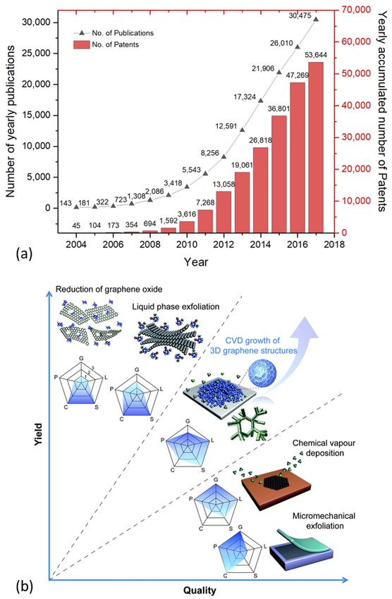
Nanomaterials 2021, 11, 382                                                                                            8 of 37

                              value and the FWHM of the G-band [124,157,159]. Wróblewska et al. [160] highlighted
                              the difficulty in comparison of materials with widely varied ID /IG ratios reported in the
                              literature. For instance, inhomogeneity of GO/r-GO may cause a difference in values
                              measured at distances of a dozen of µm. Additionally, the ratio in question also depends
                              on the laser wavelength used [160]. To reduce uncertainty, a statistical approach (Raman
                              mapping) instead of using single-point measurement should be taken [124,160]. This is
                              unfortunately not the case in every investigation.
                                    Fourier-transform infrared spectroscopy (FTIR) is also a useful tool to investigate
                              the effectiveness of GO-reduction. The presence of various oxygen-containing groups
                              can be recognized in GO/rGO, and thus their removal can be examined [161,162]. The
                              configurations that can be identified with FTIR are [163]:
                              •    epoxide (C-O-C): 1230–1320 cm−1 , asymmetric stretching; ~850 cm−1 bending motion,
                              •    sp2 -hybridized C=C: 1500–1600 cm−1 , in-plane vibrations,
                              •    carboxyl (COOH): 1650–1750 cm−1 (including C-OH vibrations at 3530 and 1080 cm−1 ),
                              •    ketonic species (C=O): 1600–1650 and 1750–1850cm−1 , and
                              •    hydroxyl (namely phenol, C-OH): 3050–3800 and 1070 cm−1 ) with all C-OH vibrations
                                   from COOH and H2 O.

                              3. Plasma-Assisted Reduction of GO
                                   Chemist Irving Langmuir coined the term “plasma” in 1928 [164], which often de-
                              notes the fourth state of matter (see Figure 3). In the visible universe, more than 99% of
                              constituents are expected to be in a plasma state (center of active stars, corona flares and
                              sunspots, magnetospheres of the earth, comet-tails, inter-stellar and inter-galactic media,
                              and in the accretion disks around black holes) as opposed to the condensed matter (solids,
                              liquids, and gases) in the form of comets, planets, and cold stars [165–167]. Plasma is the
                              ionized form of gases containing energetic ions, free electrons, highly reactive radicals,
                              and photons. The extent of ionization can range from very low values (ionized fraction in
                              the order of 10−4 –10−6 ) up to full ionization [65]. If all species in plasma have the same
                              temperature (or energy), one deals with an equilibrium plasma state. In non-equilibrium
                              plasmas, electrons have higher temperatures than the remaining species. Besides that,
                              laboratory plasma can be divided into high-temperature plasma (or fusion plasma, e.g., in
                              tokamaks, z-pinch system, etc.) and low-temperature plasma (or gas discharge) [65]. The
                              latter is relevant for us, and according to Szabó et al. [168], it can be further classified as
                              follows:
                              •    operating pressure:
                                   o      low-pressure plasma
                                   o      atmospheric pressure plasma
                              •    temperature:
                                   o      low-temperature plasma (Tgas < 2000 K)
                                   o      high-temperature plasma (Tgas > 2000 K)
                              •    thermodynamics:
                                   o      thermal plasma/equilibrium plasma (Telectron ≈ Tion ≈ Tgas )
                                   o      non-thermal plasma/non-equilibrium plasma (Telectron  Tion ≈ Tgas )
                              •    type of coupling:
                                   o      inductive coupling
                                   o      capacitive coupling
                              •    plasma generation:
                                   o      microwave discharge (300 MHz ≤ f ≤ 300 GHz)
                                   o      radiofrequency (RF) discharge (ideally 13.56 MHz):
                                   o      direct current (DC) discharge
                                   o      dielectric barrier discharge (DBD)
Plasma Assisted Reduction of Graphene Oxide Films
       type of coupling:
                                        o   inductive coupling
                                        o   capacitive coupling
                                       plasma generation:
Nanomaterials 2021, 11, 382                                                                                                   9 of 37
                                        o   microwave discharge (300 MHz ≤ f ≤ 300 GHz)
                                        o   radiofrequency (RF) discharge (ideally 13.56 MHz):
                                        o   direct current (DC) discharge
                                    o   o   dielectric barrier discharge (DBD)
                                            corona discharge
                                    o   o   corona   discharge
                                            electric arc
                                    o   o   electric arc
                                            hollow cathode   discharge
                                    o   o   hollow
                                            electroncathode  discharge(EB)
                                                      beam discharge
                                    o   o   electron  beam discharge (EB)
                                            plasma torch
                                    o   o   plasma   torch
                                            alternating  current.
                                        o   alternating current.

                                Figure
                              Figure  3. 3. Schematicofofa atypical
                                         Schematic            typicalphase
                                                                      phasediagram
                                                                            diagramdepicting
                                                                                    depictingcorresponding
                                                                                              corresponding ionized
                                                                                                            ionized states
                                                                                                                    states of
                                                                                                                           of matter.
                                                                                                                              matter.
                                Reproduced from Adamovich et al. [67] licensed under CC BY 3.0.
                              Reproduced from Adamovich et al. [67]. Copyright © 2017 IOP Publishing Ltd, licensed under CC
                              BY 3.0.

                                    Based on the operating pressure, the low-temperature plasmas can be broadly classi-
                              fied into low pressure and atmospheric pressure plasma. Traditional sources of atmospheric
                              plasma include the transferred arcs, plasma torches, corona discharges, dielectric barrier
                              discharges (DBD), and atmospheric-pressure plasma jet (APPJ) [63]. The classical arc
                              torches (ones with local thermal equilibrium) are characterized with high gas temperatures
                              and have been used in applications such as welding, cutting, spraying, etc., where heat
                              is required [169]. Relatively modern low-powered homogeneous arc plasma, generating
                              less heat, is well implanted in the production lines of automobiles, textiles, and packaging,
                              etc. [169]. Corona discharges are spatially non-uniform and are formed on sharp-points,
                              edges, or on thin-wires where the electric field is very large [170]. As the active volume is
                              limited, they are not well suited for the industrial production of large quantities of chemical
                              species [61].
                                    The DBD was developed to overcome disadvantages of the corona discharge [169].
                              Amongst the atmospheric plasmas, the DBD is better suited for the applications needing
                              volume plasma chemistry, as it caters to large volume excitation with energetic electrons for
                              excitation of atomic and molecular species breaking chemical bonds [61]. The APPJ plasma
                              shares a similar plasma density as the low-pressure plasma but with lower breakdown
                              voltage and electron temperatures than the rest of the plasmas. However, the population
                              of electrons is considered high enough to dissociate many molecules including O2 and
                              N2 [63]. The main disadvantage of the APPJs is the small area that can be treated or coated,
                              which can be circumvented with approaches such as scanning of surface area, using an
                              array of APPJs, and rotating arc root plasma jet process [171]. In a recent review [14],
Plasma Assisted Reduction of Graphene Oxide Films
Nanomaterials 2021, 11, 382                                                                                           10 of 37

                              the APPJ-plasma was emphasized to be a promising candidate for large-scale roll-to-roll
                              functionalization of graphene and GO.
                                    The low-pressure plasma emerges from the field of material processing and is a
                              key player in the semiconductor industry [172,173]. Low-pressure plasma treatment of
                              electronic devices, printed circuit boards, and semiconductors are state of the art. Uniform
                              treatment of oxidation-sensitive and three-dimensional objects can be carried out, including
                              cavities that can be processed in large chambers (up to 12,000 L in volume) [174]. They
                              feature some distinctive benefits: (1) uniform glow over large areas, (2) high concentration
                              of reactive species (able to etch or deposit at the rate of up to 10 µm/min), (3) lower
                              breakdown voltages, (4) stable operating window, and (5) sufficient electron temperatures
                              to dissociate molecules with lower gas temperature [63]. On the downside, the vacuum
                              systems are relatively expensive in assembly and maintenance. Furthermore, the processing
                              is limited by batching and transferring materials in and out of the vacuum system. Some of
                              the plasma parameters of low-pressure and atmospheric-pressure plasma are summarized
                              in Table 4.

                              Table 4. Characteristics of various plasma sources.

                                                                Breakdown Voltage   Plasma Density       Electron
                                     Plasma Source
                                                                     (kV) [63]        (cm−3 ) [63]   Temperature (eV) †
                                     Low-pressure
                                                                     0.2–0.8           108 –1013         0.1–10 [172]
                                       discharge
                                  Arc and plasma torch                10–50           1016 –1019           2–7 [63]
                                        Corona                        10–50           109 –1013            5 ‡ [61]
                                          DBD                          5–25           1012 –1015          1–10 [61]
                                       Plasma jet                    0.05–0.2         1011 –1012           1–2 [61]
                              †   1 eV ≈ 11,604 K;‡ variable.

                                   The plasma-assisted GO-reduction can be regarded analogically to the plasma etching
                              process in a way [66]. It should selectively remove oxygen-containing groups, leaving
                              the carbon network unaffected. On a solid surface exposed to the plasma, two processes
                              track simultaneously: (i) deposition of material and (ii) ablation leading to its removal.
                              Both are determined by the discharge gas and conditions [175]. The ablation of the treated
                              surface can involve sputtering, chemical etching, ion-enhanced energetic etching, and ion-
                              enhanced protective etching [66,175]. In the case of the plasma-assisted chemical etching,
                              the plasma species are excited and become chemically more reactive. In case of the ion-
                              induced etching, plasma activates surface atoms that increase their ability to release under
                              certain pressure and chemical conditions [176,177]. Admixing the inhibitor species into the
                              gas phase results in an isotropic inert coverage of the treated surface, preventing further
                              etching. In sputtering, a bombardment of the surface by the ions with sufficient kinetic
                              energy can break chemical bonds in the solid and eject atoms into a gas phase. Plasma
                              process is quite complex and dynamic where several processes occur simultaneously being
                              subjected to the plasma generation conditions.
                                   The first use of a plasma process for GO reduction was reported in the year 2007 [150],
                              two years following the first report on GO solution processing [31]. Since then, in the last
                              13 years, several kinds of plasma-assisted reduction processes were developed. To name
                              some ways plasma generation is utilized: radio-frequency (RF) plasma [150,162,178–197],
                              low-pressure direct current (DC) plasma [198–201], micro-DC plasma [202], atmospheric
                              pressure glow discharge (AGD) plasma [56], electron beam (EB) plasma [203], active screen
                              (AS) plasma [204], atmospheric pressure plasma jet (APPJ) [205] and µ-APPJ [206], and
                              dielectric barrier discharge (DBD) plasma [207,208]. In the following sections, the reduction
                              processes classified according to the discharge gas will be discussed in detail.

                              3.1. Inert-Gas (He and Ar) Plasma
                                  Zhou et al. [209] used a 60 W (AC) DBD plasma with several discharge gases (Ar, H2 ,
                              and CO2 ) for simultaneous exfoliation and reduction of GO powder. The plasma treat-
Nanomaterials 2021, 11, 382                                                                                                                     11 of 37

                                   ment mechanism suggested dictates similar for the GO-films. According to this work, the
                                   alternating electric field distorts polar bonds in oxygen-containing groups. Furthermore,
                                   high-energy electrons and ions of plasma bombard GO surface, rupturing the bonds of
                                   oxygen-containing groups within nanoseconds. Jin et al. [210] have shown by first-principle
                                   calculations that provision of an electron to the hydroxyl group favors its desorption from
                                   the GO surface. The plasmas in general have a high density of electrons (see Table 3); there-
                                   fore, desorption of hydroxyl groups must be a frequent event. Zhou et al. demonstrated
                                   that the deoxygenation of GO was strongly influenced by the discharge gas (see Figure 4).
                                   When Ar was employed, deoxygenation occurred primarily through the bombardment of
                                   energetic ions and electrons, unlike the H2 -plasma, which could also provide chemically
                                   reactive plasma species (H, H+ , H2 + , and H3 + [211]). Other authors have reported that a
Nanomaterials 2021, 11, x FOR PEER REVIEW                                                                                  12 of 38
                                   combination of inert gases and a reactive gas can be more effective in reduction compared
                                   to pure inert or reactive gas plasma; this will be discussed in the following sections.

                               Figure4.4. (a)
                               Figure      (a)A
                                              Aschematic
                                                schematicrepresentation
                                                          representationofofthe
                                                                              theDBD
                                                                                  DBDplasma
                                                                                        plasma  exfoliation
                                                                                              exfoliation ofof
                                                                                                            GO.GO.
                                                                                                                 (b)(b) RC/Oasasaafunction
                                                                                                                     RC/O          func‐
                               tion  of treatment time with  from H   , Ar, and CO    DBD  plasma. (c) FTIR  spectra of GO
                               of treatment time with from H2 , Ar, and CO2 DBD plasma. (c) FTIR spectra of GO and graphene
                                                                    2               2                                        and   gra‐
                               phene prepared
                               prepared   by DBDby   DBD plasma
                                                   plasma         with different
                                                          with different   type of type of working
                                                                                   working          gases. Reproduced
                                                                                            gases. Reproduced            frometZhou
                                                                                                                 from Zhou              et
                                                                                                                                  al. [209]
                               al. [209]  with permission from  the Royal   Society
                               with permission from the Royal Society of Chemistry. of Chemistry.

                                       Cardinali et
                                      Cardinali       et al.
                                                         al. [188]
                                                              [188] used
                                                                      usedaa2525WWRFRFplasma plasma  with
                                                                                                       withArAr
                                                                                                              forfor
                                                                                                                   simultaneous
                                                                                                                        simultaneous    thinning
                                                                                                                                             thinningand
                                reduction      of the    bulk    GO    platelets.   Starting   from  the  thickness
                               and reduction of the bulk GO platelets. Starting from the thickness of ~600 nm, the     of  ~600    nm,    the   authors
                                etched samples
                               authors                 for 40 min
                                            etched samples         fordown
                                                                         40 minto 5–6
                                                                                   down nmtothick
                                                                                               5–6 multi‐layered     film with over
                                                                                                    nm thick multi-layered          film twowithorders
                                                                                                                                                    over
                                lower
                               two       surface
                                      orders        electrical
                                                lower     surface resistivity.
                                                                     electricalAlthough       an Although
                                                                                   resistivity.   inert gas plasma
                                                                                                              an inert  does
                                                                                                                          gasnotplasmaprovidedoes chem‐
                                                                                                                                                     not
                                ically reactive
                               provide     chemicallyspecies    that species
                                                          reactive     can act that
                                                                                 as reductant,
                                                                                      can act as the  bombardment
                                                                                                  reductant,              by energetic
                                                                                                              the bombardment                inert ions
                                                                                                                                         by energetic
                                and electrons
                               inert                 have proven
                                       ions and electrons         havetoproven
                                                                            be adequate      for deoxygenation
                                                                                     to be adequate                  in some reports.
                                                                                                        for deoxygenation         in some Bo        et al.
                                                                                                                                               reports.
                                [200]
                               Bo       used
                                    et al.     an used
                                            [200]  instantaneous        2‐s atmospheric‐pressure
                                                          an instantaneous                              glow discharge
                                                                                   2-s atmospheric-pressure                  processprocess
                                                                                                                 glow discharge          with heliumwith
                                for preparing
                               helium               rGO‐paper.
                                           for preparing             The plasma‐treated
                                                               rGO-paper.                       rGO‐paper
                                                                                The plasma-treated           (σ: 59 S/cm;
                                                                                                         rGO-paper           RC/O
                                                                                                                        (σ: 59     : 7.6) was
                                                                                                                                 S/cm;      RC/Oon    par
                                                                                                                                                   : 7.6)
                                withon
                               was     theparone  reduced
                                               with    the one  chemically     by hydrazine
                                                                  reduced chemically             hydrate (σ:hydrate
                                                                                            by hydrazine      65 S/cm;  (σ:RC/O
                                                                                                                             65 :S/cm;
                                                                                                                                  8.5). TheRC/O authors
                                                                                                                                                   : 8.5).
                               The   authorsinstantaneous
                                attributed       attributed instantaneous
                                                                    deoxygenation    deoxygenation      with their
                                                                                         with their plasma     to theplasma
                                                                                                                        synergy to ofthehigh‐density
                                                                                                                                          synergy of
                               high-density
                                electrons andelectrons
                                                    heating.and  Theheating.
                                                                        electronThe     electron
                                                                                    density  and density    and gas
                                                                                                   the neutral   the neutral     gas temperature
                                                                                                                       temperature        were deter‐
                               were    determined                             16 cm−3 and ~800 K, respectively. Herewith, no damage
                                                                        × 10~800
                                mined     to be 1.03 ×to10be     1.03
                                                             16 cm  −3 and          K, respectively. Herewith, no damage to the graphitic
                               to  the  graphitic      structure     was
                                structure was found by Raman spectroscopy. found     by Raman spectroscopy.
                                                                                                   The r‐GO layers  The reduced
                                                                                                                           r-GO layers   by reduced
                                                                                                                                              inert‐gas
                               by   inert-gas    plasma     have    been   demonstrated       in supercapacitors
                                plasma have been demonstrated in supercapacitors [200] and H2O2 chemical2sensors     [200]   and    H   O  2 chemical
                                                                                                                                                   [162].
                               sensors Kim [162].
                                              et al. [212] accomplished selectively etching an atomic‐layer of graphene without
                                      Kim etthe
                                damaging        al. underneath
                                                     [212] accomplished         selectively
                                                                      layers using            etching an atomic-layer
                                                                                       an inductively‐coupled               of graphene
                                                                                                                    plasma‐type        ion beamwithout
                                                                                                                                                     sys‐
                               damaging
                                tem (see Figurethe underneath
                                                        5a). The cycliclayers   usingprocess
                                                                            etching      an inductively-coupled
                                                                                                  used consisted of plasma-type
                                                                                                                         chemical adsorptionion beam    of
                               system     (see   Figure    5a).  The    cyclic  etching   process   used   consisted
                                low‐energy oxygen‐ions: O2 and O (0–20 eV) followed by physical desorption of oxidized
                                                                        +        +                                      of chemical       adsorption
                               of  low-energy        oxygen-ions:            +        O+ the
                                species     by Ar+‐ions      (11.2 eV).OTo 2 andcontrol   (0–20   eV) followed
                                                                                               energy              by authors
                                                                                                        of ions, the    physicalapplied
                                                                                                                                      desorption       of
                                                                                                                                                 floated
                                and grounded grids with an axial magnetic field. This approach helped to optimize the
                                process based on ion energy distribution for various power and gas‐flows in the system
                                (see Figure 5b–e). This cyclic etch‐process exploited the fact that the binding energy of the
                                surface C‐atoms decreases from ~6.1 to ~3.9 eV with chemisorption of oxygen ions. At the
                                same time, the C–C binding energy in the underneath layer remains almost unchanged
Nanomaterials 2021, 11, 382                                                                                                                  12 of 37

                                     oxidized species by Ar+ -ions (11.2 eV). To control the energy of ions, the authors applied
                                     floated and grounded grids with an axial magnetic field. This approach helped to optimize
                                     the process based on ion energy distribution for various power and gas-flows in the system
                                     (see Figure 5b–e). This cyclic etch-process exploited the fact that the binding energy of the
                                     surface C-atoms decreases from ~6.1 to ~3.9 eV with chemisorption of oxygen ions. At the
                                     same time, the C–C binding energy in the underneath layer remains almost unchanged
                                     (~0.1 eV). Exactly this fact in combination with controlled energy of Ar+ -ions has allowed
   Nanomaterials 2021, 11, x FOR PEERetching
                                      REVIEW of the top layer selectively. This experience opens the way to combine the 13
                                                                                                                         chemical
                                                                                                                           of 38
                                     and energetic impacts of plasma species for effective and controlled GO reduction.

                                  Figure 5. (a) Schematic of a two‐grid ICP‐type ion beam system with axial magnetic field used for
                                Figure 5. (a) Schematic of a two-grid ICP-type ion beam system with axial magnetic field used for
                                  atomic layer etching of graphene with a quadrupole mass spectrometer (QMS, for ion energy/flux
                                atomic layer etching of graphene with a quadrupole mass spectrometer (QMS, for ion energy/flux
                                  measurement of the ion beam). (b) Various RF powers at 70 sccm of Ar gas flow rate and (c) the
                                measurement
                                  correspondingofpeakthe energies
                                                          ion beam).
                                                                   and(b)
                                                                       fluxVarious
                                                                             for theirRF
                                                                                       Arpowers    at 70distributions.
                                                                                          +‐ion energy    sccm of Ar gas    flow rate
                                                                                                                       (d) Various  Arand
                                                                                                                                       flow(c) the
                                corresponding
                                  rates at 500 Wpeak     energies
                                                   RF power       and flux
                                                              measured   byfor
                                                                             an their Ar+ -ion
                                                                                 ion energy     energyin
                                                                                              analyzer  distributions.
                                                                                                           the QMS and(d)(e)Various  Ar flow rates
                                                                                                                             are the corre‐
                                atsponding
                                   500 W RFpeak     energies
                                                power        and fluxes
                                                        measured    by anfor
                                                                           iontheir Ar+‐ion
                                                                                energy       energyindistributions.
                                                                                         analyzer      the QMS and  Reproduced
                                                                                                                      (e) are thefrom   Kim et
                                                                                                                                   corresponding
                                  al. [212]
                                peak        licensed
                                       energies   andunder
                                                       fluxesCC
                                                              forBY 4.0. Ar+ -ion energy distributions. Reproduced from Kim et al. [212].
                                                                  their
                                Copyright © 2017 Authors, licensed under CC BY 4.0.
                                  3.2. Hydrogen Plasma
                                3.2. Hydrogen
                                        A hydrogenPlasmagas discharge can constitute free electrons, neutrals (molecular H2,
                                       A hydrogen
                                  atomic             gas discharge
                                           H), and charged    ions (Hcan+, Hconstitute      free electrons,
                                                                            −, H2+, H3+) interacting           neutrals
                                                                                                           through    a set(molecular
                                                                                                                            of numerous  H2 ,reac‐
                                                                                                                                               atomic
                                H),  and
                                  tions    charged
                                        [213].        ions (H+ , H
                                               A bombardment        by− ,H,HH
                                                                            2
                                                                              ++, HH 2+,+and
                                                                                      3  ) interacting
                                                                                              H 3 + speciesthrough
                                                                                                             with      a set
                                                                                                                   energies   of  numerous
                                                                                                                              varying    from    reac-
                                                                                                                                                10
                                  eV  to few   hundred    of eV  is  known     to+       +
                                                                                    result   in the   +
                                                                                                      etching   of
                                tions [213]. A bombardment by H, H , H2 , and H3 species with energies varying from graphene    [214–216].     The
                                10impact
                                    eV to of
                                           fewhydrogen
                                                 hundred  plasma
                                                            of eV on   GO is similar
                                                                    is known               to the
                                                                                   to result        etching
                                                                                               in the         effect
                                                                                                        etching    ofand   removal[214–216].
                                                                                                                      graphene       of oxygen‐The
                                  containing
                                impact          groups [193,194,208].
                                          of hydrogen    plasma on GO      A ismolecular
                                                                                 similar todynamics
                                                                                                the etching study    [215]
                                                                                                                effect  andon   graphene
                                                                                                                             removal          sug‐
                                                                                                                                         of oxygen-
                                  gested thatgroups
                                containing      surface  reaction strongly
                                                       [193,194,208].           varies with
                                                                          A molecular            incident
                                                                                            dynamics         atomic
                                                                                                          study       H on
                                                                                                                  [215]  energy:   (i) atomic
                                                                                                                             graphene            H
                                                                                                                                          suggested
                                  withsurface
                                that    few tenths   of eVstrongly
                                                reaction    can adsorb     on the
                                                                       varies     withbasal  plane of
                                                                                          incident       surface‐clean
                                                                                                      atomic     H energy:graphene,    (ii) HHen‐
                                                                                                                               (i) atomic        with
                                  ergies 0.025–0.3 can selectively etch edges without damaging the basal plane, (iii) H ener‐
                                  gies in the range 0.3–10 eV hydrogenates basal plane without irreversibly damaging gra‐
                                  phene (hydrogenation is reversible), (iv) H energies in the range 10–100 eV are suitable
                                  for patterning multi‐layer graphene, and (iv) 10 eV H+ ions can etch graphene vertically
                                  and the hydrogen plasma containing more molecular (H2+ and H3+) than atomic (H+) ions
Nanomaterials 2021, 11, 382                                                                                            13 of 37

                              few tenths of eV can adsorb on the basal plane of surface-clean graphene, (ii) H energies
                              0.025–0.3 can selectively etch edges without damaging the basal plane, (iii) H energies in
                              the range 0.3–10 eV hydrogenates basal plane without irreversibly damaging graphene
                              (hydrogenation is reversible), (iv) H energies in the range 10–100 eV are suitable for pat-
                              terning multi-layer graphene, and (iv) 10 eV H+ ions can etch graphene vertically and the
                              hydrogen plasma containing more molecular (H2 + and H3 + ) than atomic (H+ ) ions may
                              induce less subsurface damage in multi-layered graphene. Such detailed studies are yet to
                              be reported for GO materials.
                                   Kim et al. [193] applied optical emission spectroscopy (OES) to determine the optimum
                              process point for GO-reduction to avoid the degradation of electrical characteristics with
                              excess plasma exposure. The emission corresponding to the oxygen radicals released from
                              GO was used as an indicator of the reduction progress (see Figure 6a–c). As observed in
                              Figure 6c, at point C (~18 s after the start of the reduction process), the intensity of the OES
                              oxygen-line begins to decline, indicating the end of reduction. A crucial application of the
                              OES lies in the determination of the excited states of species in the plasma. Li et al. [190]
                              studied with this method the effect of variable plasma power and different gas mixtures
                              (Ar/H2 ) on the reduction of GO. The emission corresponding to atomic hydrogen (in OES
                              spectra, Figure 6d–g) was found to increase with increasing discharge power and reached
                              an overall maximum for the H2 /Ar ratio 2:1. The inclusion of Ar assisted in the enhanced
                              dissociation of H2 due to the penning ionization. The GO (RC/O : 1.1) on reduction with
                              a pure Ar and H2 plasma yielded rGO with RC/O of 1.2 and 1.7, respectively. However,
                              the rGO obtained with a more populous H2 /Ar plasma (2:1) resulted in a RC/O up to 6.9.
                              Furthermore, the electrochemical performance of the fabricated rGO was demonstrated as
                              an electrode (in KOH aqueous electrolyte), achieving a specific capacitance of 185.2 F/g.
                              The performance was higher than several graphene-based electrodes in literature.

                              3.3. Methane Plasma
                                   To obtain graphene-like quality with GO as precursors, numerous investigations into
                              reduction with healing (or repair) of defects has been carried out. By incorporating C-
                              atoms into structural defects of GO, the sp2 -hybridized graphene domains are restored.
                              Various strategies employed include thermal-CVD [92,217–219] and high-temperature
                              graphitization [142,220]. In a recent review, De Silva et al. [48] addressed the defect repair
                              of GO mostly with thermal methods. This section is devoted to the plasma-enhanced
                              CVD approach, which is more attractive in terms of large-scale applications than the
                              others mentioned.
                                   Methane plasma is a popular choice for the defect repair and reduction of GO. Pure
                              discharge of CH4 [93], as well as in combination with Ar [180,185,203] or H2 [179,184,189,
                              207,221], has been utilized. Cheng et al. [93] treated GO-monolayers on Si/SiO2 substrates
                              with CH4 -plasma (100 W, RF, ~575 ◦ C, 10 min) that resulted in a decrease of the ID /IG ratio
                              from 1.03 to 0.53, indicating healing of defects and increasing conversion of sp2 C-atoms.
                              They reported one of the highest conductivities (1590 S/cm) for rGO. Baraket et al. [203]
                              used plasma generated in a CH4 (0–20%)/Ar gas mixture by electron-beam, resulting in the
                              energy of electrons and dissociated ions
Nanomaterials 2021, 11, x FOR PEER REVIEW                                                                                            14 of 38
Nanomaterials 2021, 11, 382                                                                                                                 14 of 37

                                       Kim et al. [193] applied optical emission spectroscopy (OES) to determine the opti‐
                                 mum
                                   pureprocess   point for
                                          CH4 plasma        GO‐reduction
                                                         [221];                to avoid
                                                                (ii) many defects        thedistortions
                                                                                       and   degradation  of of electrical characteristics
                                                                                                             a graphitic   network are bound
                                 with   excess plasma   exposure.    The emission     corresponding    to the
                                   and eliminated by the hydrogen active species and serve at once as active   oxygen   radicals released
                                                                                                                               sites  for carbon
                                 from   GO  was  used  as an indicator   of  the  reduction  progress   (see  Figure  6a–c). As
                                   species from plasma to react [179,184], and (iii) the etching nature of H2 plasma restricts  observed
                                 indeposition
                                     Figure 6c, at
                                                of point  C (~18 s after
                                                    sp3 amorphous          the start
                                                                       carbon     fromofradicals
                                                                                         the reduction    process),CH
                                                                                                  of dissociated     the intensity   of the
                                                                                                                        4 molecules [179,189].
                                 OES   oxygen‐line   begins   to decline,   indicating   the end  of reduction.    A  crucial
                                   The substrate temperature, CH4 /H2 ratio, other plasma conditions, and treatment runtime   application
                                 ofsensitively
                                     the OES liesinfluence
                                                   in the determination
                                                             the relative of    the excited
                                                                              rates          states
                                                                                     of etching  and of carbonization
                                                                                                        species in the plasma.
                                                                                                                          (defectLi   et al.
                                                                                                                                   restoration).
                                 [190]  studied  with  this method    the  effect  of variable plasma    power    and
                                   Bodik et al. [207] used an instantaneous DBSCD plasma reduction (100 W/cm equimolec-different gas
                                                                                                                                   3  mix‐
                                 tures (Ar/H2) on the reduction of GO. The emission corresponding to atomic hydrogen (in
                                   ular CH4 /H2 ratio, atmospheric pressure, 5 s) of the unheated GO films, and observed that
                                 OES spectra, Figure 6d–g) was found to increase with increasing discharge power and 2
                                   this treatment was effective in the removal of oxygen-functional groups but not in sp -C
                                 reached an overall maximum for the H2/Ar ratio 2:1. The inclusion of Ar assisted in the
                                   restoration. Nevertheless, such a plasma process can promote application on temperature-
                                 enhanced dissociation of H2 due to the penning ionization. The GO (RC/O: 1.1) on reduction
                                   sensitive flexible substrates. Chiang et al. [221] performed a reduction of GO-nanoribbons
                                 with a pure Ar and H2 plasma yielded rGO with            RC/O of 1.2 and 1.7, respectively. However,
                                   films with an RF CH /H2 plasma at 230 ◦ C. Impressively, even at this moderate tempera-
                                 the rGO obtained with4a more         populous H2/Ar plasma (2:1) resulted in a RC/O up to 6.9.
                                   ture, the removal of all kinds of oxygen-containing groups (C-O, C=O, and COOH) down
                                 Furthermore, the electrochemical performance of the fabricated rGO was demonstrated
                                   to < 1–1.2 at.% surface concentration was determined by XPS analysis. The I /IG ratio
                                 as an electrode (in KOH aqueous electrolyte), achieving a specific capacitance of 185.2DF/g.
                                   remained
                                 The           however
                                       performance    was quite
                                                           higherhigh:
                                                                    than 0.83.
                                                                          several graphene‐based electrodes in literature.

                                 Figure 6. Emission spectra of H2 discharge without GO (a) and with GO sample (b) in the plasma
                                   Figure 6. Emission spectra of H2 discharge without GO (a) and with GO sample (b) in the plasma
                                 treatment chamber, indicating the active species. (c) The OES signal from the 844.6 nm oxide line
                                   treatment chamber, indicating the active species. (c) The OES signal from the 844.6 nm oxide line
                                 (shown in (b)) during the reduction of GO. A–E in (c) are various process points where the rGO
                                   (shown   in (b)) during
                                 sample properties          the reduction
                                                     were investigated        of GO. A–E
                                                                        in literature  [193].inReproduced
                                                                                                 (c) are various
                                                                                                             fromprocess    points
                                                                                                                    Kim et al. [193] where
                                                                                                                                      licensedthe rGO
                                   sample
                                 under   CCproperties  were investigated
                                            BY 3.0. Emission  spectra of H2in  literature
                                                                             /Ar  plasma as[193].  Reproduced
                                                                                              a function          fromofKim
                                                                                                          of the ratio       et Ar
                                                                                                                          H2 to  al. [193]. Copyright
                                                                                                                                     (d,e) and
                                 discharge  power (f,g).
                                   © 2013 Authors,       Lines under
                                                     licensed  corresponding
                                                                      CC BY 3.0. to Ar  excited states
                                                                                     Emission           andofatomic
                                                                                                  spectra     H2 /Arhydrogen
                                                                                                                       plasma as (Haα and  Hβ) of the
                                                                                                                                       function
                                 are indicated.
                                   ratio of H2 toReproduced  from
                                                  Ar (d,e) and     Li et al.power
                                                               discharge     [190]. Copyright
                                                                                    (f,g). Lines©corresponding
                                                                                                    2014 AmericantoChemical     Society.
                                                                                                                       Ar excited   states and atomic
                                   hydrogen (Hα and Hβ ) are indicated. Reprinted with permission from Li et al. [190]. Copyright ©
                                   2014 American Chemical Society.
You can also read