PORT LINCOLN AIRPORT MASTERPLAN 2016 - District Council of Lower ...
←
→
Page content transcription
If your browser does not render page correctly, please read the page content below
PORT LINCOLN AIRPORT
    MASTERPLAN

       2016

                       June 2016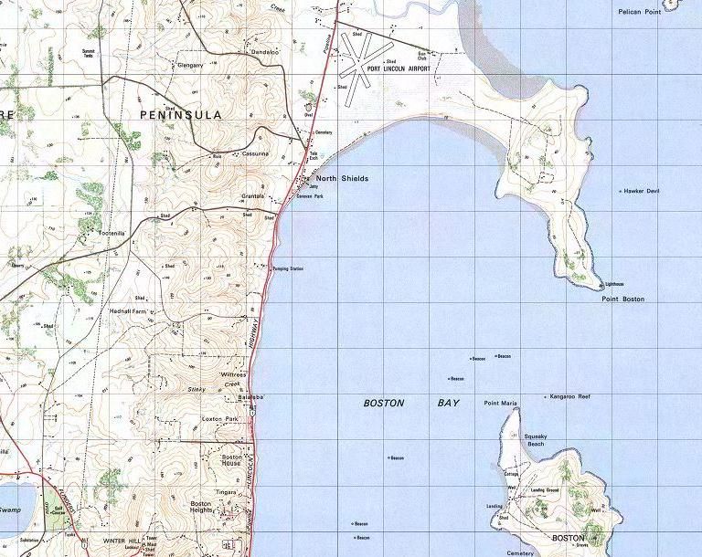
Port Lincoln Master Plan

1   INTRODUCTION ........................................................................................................................................ 3
  1.1    Overview of the Airport.................................................................................................................... 3
  1.2    Purpose and Objectives of the Master Plan....................................................................................... 3
  1.3    Methodology and Consultation ........................................................................................................ 4
  1.4    Report Structure .............................................................................................................................. 4
2   MASTER PLAN CONTEXT ........................................................................................................................... 4
  2.1    Historical Background....................................................................................................................... 4
  2.2    Regional Context .............................................................................................................................. 4
  2.3    Socio-Economic Context ................................................................................................................... 5
  2.4    Regulatory Context .......................................................................................................................... 5
  2.5    Policy Context .................................................................................................................................. 5
  2.6    Previous and Current (Master) Plans ................................................................................................ 6
  2.7    Key Stakeholders.............................................................................................................................. 6
3   CURRENT SITUATION ................................................................................................................................ 7
  3.1    Ownership and Management ........................................................................................................... 7
  3.2    Site Description ................................................................................................................................ 7
  3.3    Surrounding Land ............................................................................................................................. 7
  3.4    Existing Activities ............................................................................................................................. 7
  3.5    Existing Facilities .............................................................................................................................. 7
  3.6    Ground Transport Access ................................................................................................................. 9
  3.7    Utility Services ................................................................................................................................. 9
  3.8    Environmental Values ...................................................................................................................... 9
  3.9    Heritage Values ................................................................................................................................ 9
4   STRATEGIC VISION AND OBJECTIVES ....................................................................................................... 10
  4.1    Strategic Vision .............................................................................................................................. 10
  4.2    Objectives ...................................................................................................................................... 10
5   CRITICAL AIRPORT PLANNING PARAMETERS ........................................................................................... 11
  5.1    Forecast of Regional Passenger Movements ................................................................................... 11
  5.2    Airport Capacity ............................................................................................................................. 13
  5.3    Aerodrome Reference Code System ............................................................................................... 14
  5.4    Selected Design Aircraft ................................................................................................................. 15
  5.5    Runway configuration .................................................................................................................... 16
  5.6    Navigation Systems ........................................................................................................................ 18
  5.7    Aviation Support and Landside Facilities ......................................................................................... 18
  5.8    Airspace Protection Surfaces .......................................................................................................... 20
  5.9    Aircraft Noise Contours .................................................................................................................. 20
  5.10 Environmental and Heritage Sites................................................................................................... 23
6   LAND USE PLAN ...................................................................................................................................... 24
  6.1    Land Use Precincts ......................................................................................................................... 24
  6.2    Land Use Precinct Guidelines.......................................................................................................... 24
7   FACILITY DEVELOPMENT PLAN................................................................................................................ 28
  7.1    Movement Area Facilities ............................................................................................................... 28
  7.2    Aviation Support Facilities .............................................................................................................. 28
  7.3    Other Facilities ............................................................................................................................... 28
8   GROUND TRANSPORT PLAN.................................................................................................................... 28
9   ENVIRONMENTAL MANAGEMENT PLAN ................................................................................................. 28
10 HERITAGE MANAGEMENT PLAN ............................................................................................................. 28
11 AIRPORT SAFEGUARDING PLAN .............................................................................................................. 29
  11.1 National Airports Safeguarding Framework (NASF) ......................................................................... 29
  11.2 Airspace Protection Surfaces .......................................................................................................... 30
  11.3 Aircraft Noise Contours .................................................................................................................. 31
  11.4 Planning Policies and Controls ........................................................................................................ 31
12 IMPLEMENTATION PLAN ........................................................................................................................ 32
13 DRAWINGS ............................................................................................................................................. 33

Draft Version June 2016                                                                                                                            Page 2
Port Lincoln Master Plan

1     INTRODUCTION
This Master Plan has been prepared in accordance with guidelines set by the Planning and Transport
Policy section of the South Australian Department of Planning, Transport and Infrastructure. This
plan replaces the 2006 master plan prepared by Airport Technical Services commissioned by the
DCLEP which itself was an update of the November 2000 master plan.

Significant physical changes have occurred on the airport since the 2006 Master Plan was adopted.
These changes include the construction of a new Airport Terminal building, new high strength
taxiway, extension of the Regular Passenger Transport (RPT) aircraft parking ramp and a new 180 bay
public car park.

1.1       Overview of the Airport
Port Lincoln Airport is located 14 km north of the Port Lincoln CBD and provides the primary aviation
gateway to the Eyre Peninsula. The existing airside infrastructure incorporates a 3-runway layout.

           The sealed 01/19 north/south runway is 1499 metres long and 30 metres wide and is suitable
           for use by BAE 146 aircraft (maximum weight 46,000 kg). The largest aircraft currently using
           the facility on a regular basis are the commuter turbo prop Saab SF 340 aircraft (12,927 kg)
           and the DHC8 300 (19,540 kg). The runway is rated as non-precision instrument and has
           published instrument procedures for a straight-in GPS approach to runway 19 from the north
           and a non-directional beacon (NDB) circling approach.

           The gravelled 15/33 northwest/southeast runway is 1450m long; it can be used by Regular
           Public Transport (RPT) commuter aircraft when the pavement is dry. During Instrument Flight
           Rules (IFR) conditions, taking off by RPT aircraft is permitted to the southeast only; IFR
           landings are not permitted on this runway.

           The 05/23 northeast-southwest runway is 1275m long and is limited to use by light aircraft
           only as terrain constraints do not permit use by RPT aircraft.

The RPT sealed apron is capable of handling 2 Saab SF 340 and 1 DHC8 300 or 400 series aircraft
simultaneously. Primary access is via a sealed taxiway off the 15/33 Runway with a sealed connection
to runway 01/19.

The General Aviation (GA) Apron is capable of handling 2 x SF 340 series aircraft including the
refuelling bay.

1.2       Purpose and Objectives of the Master Plan
The purpose of the Master Plan is to provide a detailed guide for the development of Airport
infrastructure.

The key objectives of the Master Plan are:

      -    provide an easily understood planning framework covering aviation and non-aviation
           development over the next 20 years;
      -    to ensure future development enhances the aviation safety aspects of the airport;
      -    to encourage value adding development and business ventures on the airport;
      -    to guide the land use surrounding the airport; and,
      -    to guide the provision of future access requirements for the airport.

Draft Version June 2016                                                                         Page 3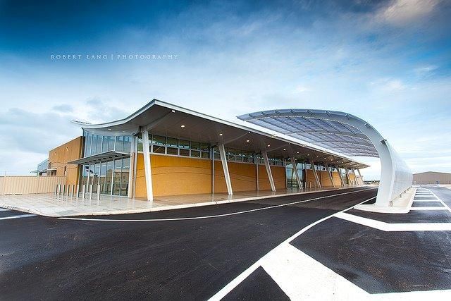
Port Lincoln Master Plan

1.3       Methodology and Consultation
The Master Plan has been developed by the DCLEP Master Plan Committee through a series of
meetings and in consultation significant stakeholders.

A public consultation process prior to submission of the completed plan will involve;

      -    distribution of the draft plan for review;
      -    consultation with local businesses and aviation industry stakeholders;
      -    advertising in local newspapers; and,
      -    placing the Master Plan on the Council's web-site and social media pages.

1.4       Report Structure
This document comprises 2 parts; - background information - Sections 1-3, and Master Planning -
Sections 4 onwards.

2     MASTER PLAN CONTEXT

2.1       Historical Background
The Port Lincoln Airport is South Australia’s largest and busiest regional airport. The facility provides
public landing strips and associated taxiway, apron, terminal, aircraft hangars and refuelling facilities
for all air transport operators.

The airport is of strategic importance, servicing many of Eyre Peninsula communities and industry.
Regular passenger transport provides up to 12 services per day between Port Lincoln and Adelaide.

The airport consists of a 3-runway layout with the capacity to handle BAe 146 aircraft, Saab SF 340
aircraft and the Embraer 120 (12,134 kg). A sealed apron is capable of handling 3 RPT Saab sized
aircraft simultaneously.

Port Lincoln Airport is located 14km north of the city of Port Lincoln. In terms of passenger numbers
it is South Australia's busiest regional airport. It is owned and operated by the DCLEP following
transfer from the Commonwealth under the Aerodrome Local Ownership Plan in 1990. The
aerodrome was previously owned and operated by the Department of Civil Aviation.

During the 1960s, the Port Lincoln Airport was the major regional port, with scheduled flights via the
Airlines of South Australia Fokker F27 Friendship. Since then, the airport has undergone various
expansions including sealing of the main runway and later upgrades to the terminal and apron
facilities as part of the transfer arrangements from the commonwealth.

In 2013 the airport completed construction of a modern new terminal, with supporting infrastructure
(RPT apron extension, new taxiway, road network and 180 bay car park)

2.2       Regional Context
Port Lincoln is the busiest regional airport in South Australia. The city is situated 45 minutes flying
time from Adelaide (compared to more than 7 hours by road). The city had a population of 14,574 in
2012 Australian Bureau of Statistics http://stat.abs.gov.au/. The airport reached nearly 200,000
passenger movements in 2010-11. This is around 70% more movements compared to the next

Draft Version June 2016                                                                           Page 4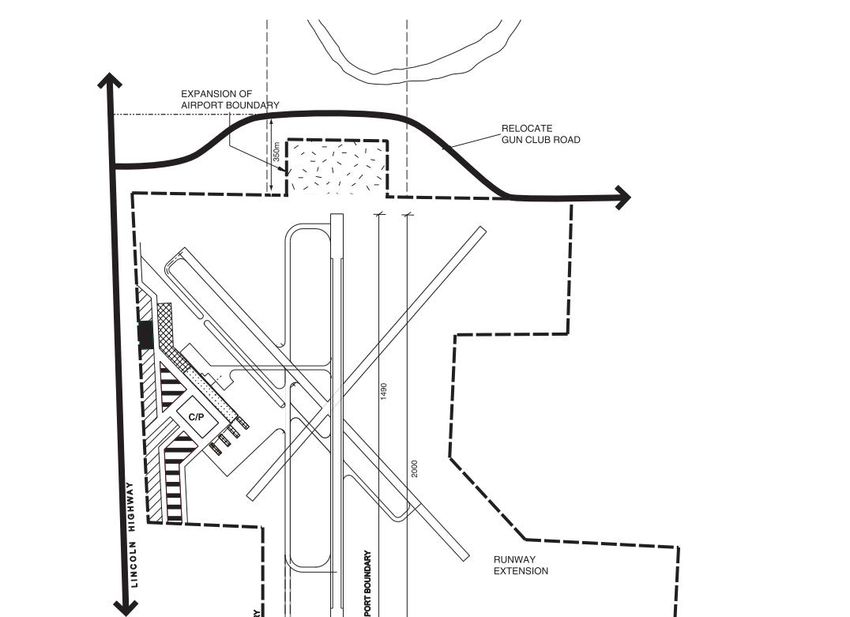
Port Lincoln Master Plan

busiest regional airport (Mount Gambier) in SA despite serving a population of only 56% of Mount
Gambier’s population.

The short flying time of 35 - 45 minutes to Adelaide compared to 7 hours by road makes air travel a
far more attractive option in comparison to other centres. Ceduna (402km by road from Port
Lincoln) and Whyalla (267km) are the only centres on the Eyre Peninsula to receive RPT services. The
airport is therefore strategically placed to continue to be a primary transport mode for business,
personal and tourism travel.

The principal industries of the region are agriculture, fishing, aquaculture and mining.

2.3       Socio-Economic Context

The airport forms a vital part of the local transport infrastructure providing regular and frequent
access for business, tourism and private flying and patient transfer year round, 7 days a week.

The Airport serves as a base for aviation fire-fighting contractors to the Country Fire Service SA
Region 6 between the months of November-April annually

The Airport supports 27 full-time jobs and generates Gross Regional Product (value added) of
approximately $36.0 million annually.

2.4       Regulatory Context
Port Lincoln is a Civil Aviation Safety Authority (CASA) certified airport and is required to meet CASA
standards as specified in Civil Aviation Safety Regulation 139 and the Manual of Standards Part 139 -
Aerodromes.

The airport receives RPT services and consequently a security designated airport requiring
compliance with the Commonwealth Aviation Transport Security Regulations 2005. The regulations
require controlled access to airside. Current RPT aircraft are less than 20 tonnes; meaning that
electronic screening of passenger and luggage is not required.

2.5       Policy Context
The continued ownership and development of the Port Lincoln Airport is supported by:

      •    DCLEP Development Plan February 2015.
      •    DCLEP Development Strategic Plan
      •    Long Term Financial Plan

National perspective:
Airports are critical pieces of national infrastructure and suitable locations are scarce. The current
and future viability of aviation operations at Australian airports can be threatened by inappropriate
development. Communities under flight paths and near airports can be affected by issues including
noise, development restrictions and safety risks.

In the interest of safety and public amenity, development needs to be carefully managed in the
vicinity of airport operations. However, there is also a need for airports to be easily accessible to

Draft Version June 2016                                                                              Page 5
Port Lincoln Master Plan
population centres and for developments to be undertaken in a way that is compatible with airport
operations, both now and into the future.
The National Airports Safeguarding Framework (NASF) was developed with the above in mind and
comprises overarching Principles and Guidelines. Section 11 of this Master Plan (Airport Safeguarding
Plan) provides further detailed information on the Framework.
State-wide Perspective:
The SA Government has seven strategic priorities. These include making South Australia an
affordable place to live. The quality of life for South Australians is influenced by the rising costs of
housing, transport and utilities. Regional airports are an important component of the transport
sector.
SA Government Strategic Plan targets include the provision of key economic and social infrastructure
to accommodate population growth. The Eyre Peninsula is a significant region for agriculture,
aquaculture and tourism.
Regional population levels are anticipated to increase in regional areas, by 20,000 to 30,000 or more
by 2020. Air access to the Lower Eyre Peninsula is a key component for the projected increased
population.
Increased visitor expenditure in South Australia’s total tourism industry is expected to exceed $8
billion by 2020.
The South Australian Government Integrated Transport and Land use Plan provides guidance to
maintain aviation assets – and continues to actively support local councils and airport owners in
maintaining regional and remote aviation assets and identify upgrades of strategically important
local airports.
2.6 Previous and Current (Master) Plans
In May 2005, the State Government announced its intention to investigate the potential for the
development of the airport to cater for large jets (Airbus A320, Boeing 737) to service tourism
markets out of the east coast capital cities. The introduction of this type of aircraft was seen by the
State Government (at the time) as being crucial to the economic development of the Eyre Peninsula.
The previous Airport Master Plan, prepared by Airport Technical Services in 2006, did not take on the
role of justifying the introduction of jet services; but provided a planning model that catered for
possible introduction of larger jet aircraft, should such an event occur.
2.7 Key Stakeholders
Key Stakeholders essential to the ongoing daily serviceability and amenity of airport operations:
• Airlines – Qantaslink, Regional Express
• Hire Car agencies
• Aircraft Repair Service
• AVGAS, AVTUR Refuelling Service
• Taxi and Shuttle Bus service
• Qualified trades with thorough knowledge of Airport infrastructure such as Electricity
distribution, Water, Sewer and HVACV Systems
Draft Version June 2016 Page 6Port Lincoln Master Plan
3 CURRENT SITUATION
3.1 Ownership and Management
Port Lincoln Airport has been wholly owned and managed by the DCLEP since its acquisition from the
Department of Civil Aviation in July 1990. The management structure consists of the Airport
Manager reporting to the Director of Works and Infrastructure who in turn reports to the Chief
Executive Officer and the Elected Council members.
At the time of acquisition, the DCLEP undertook not to utilise ratepayer funding to support airport
operations. This is still the case and the Airport Reserve pays an annual dividend to Council’s
consolidated revenue.
3.2 Site Description
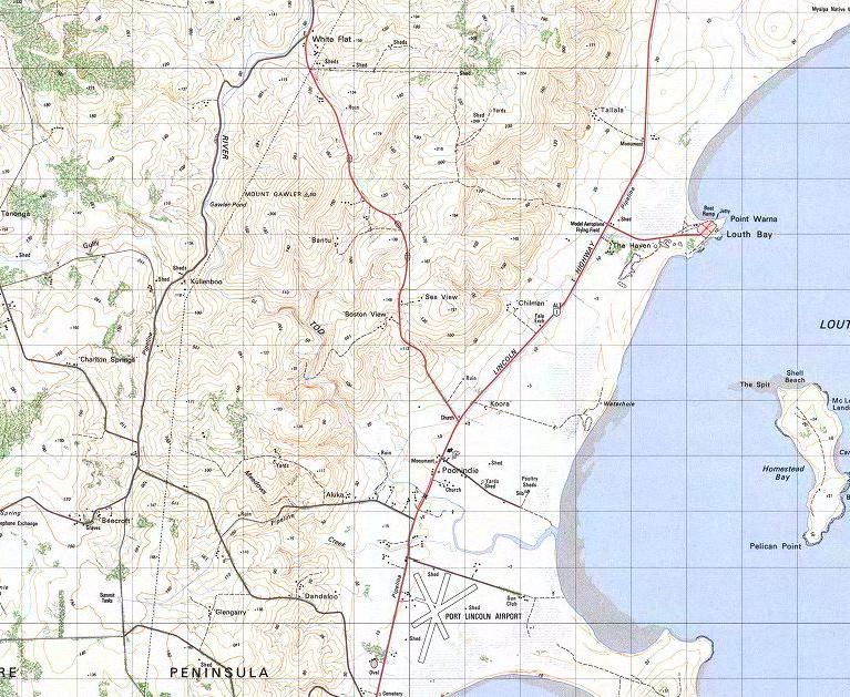
The airport is situated approximately 14 kilometres north of centre Port Lincoln. The airport slopes
from an elevation of 13m in the northwest corner down to a level of 2m to the southeast. Road
access is directly off the Lincoln Highway which connects Port Lincoln to Whyalla.
3.3 Surrounding Land
The area surrounding comprises hilly terrain 5km to the west which rises to 165m above the airport.
The Spencer Gulf shoreline extends the length of the airport south-eastern boundary and in part
comprises coastal swamp. The remaining sectors north, west and south are used for farming,
generally cropping and stock. The settlement of North Shields is 1.7km to the South, Poonindie 2km
to the north and Louth Bay 8.0km to the Northeast. (measurements from the airport perimeter)
3.4 Existing Activities
Aviation activities comprise:
- RPT flights to and from Adelaide with Qantas ink Q300 Regional Express SAAB 340 aircraft
operating around 11 flights daily (the actual number varies on weekends etc.
- Aircraft maintenance facilities (Tuna City Aviation).
- Aircraft Charter (Lincoln Air Charter).
- There are a number GA aircraft based at Port Lincoln Airport used for a range of activities
including fish sporting, charter, private / recreational aircraft. There is also an aero club.
- The Royal Flying Doctor Service also makes regular visits using PC12 aircraft.
- During the summer months the Air Tractor firebombing aircraft are located on the airport
- Aircraft refuelling services (Avfuel SA).
Non aviation activities include:
- Secure car park / General car parking area / Hire Car services.
- Taxi Services and Shuttle Bus.
3.5 Existing Facilities
Runway and Taxiways
The existing airside infrastructure incorporates a 3-runway layout. The sealed 01/19 north/south
runway is 1499 metres long and 30 metres wide and is suitable for use by BAE 146 aircraft (maximum
weight 46,000 kg). The largest aircraft currently using the facility on a regular basis are the
commuter turbo prop Saab SF 340 aircraft (12,927 kg) and the DHC8 300 (19,540 kg). The runway is
rated as non-precision instrument and has published instrument procedures for a straight-in GPS
approach to runway 19 from the north and a non-directional beacon (NDB) circling approach.
Draft Version June 2016 Page 7Port Lincoln Master Plan
The gravelled 15/33 northwest/southeast runway is 1450m long; it can be used by Regular Public
Transport (RPT) commuter aircraft when the pavement is dry. During Instrument Flight Rules (IFR)
conditions, taking off by RPT aircraft is permitted to the southeast only; IFR landings are not
permitted on this runway.
The 05/23 northeast-southwest runway is 1275m long and is limited to use by light aircraft only as
terrain constraints do not permit use by RPT aircraft.
The RPT sealed apron is capable of handling 2 Saab SF 340 and 1 DHC8 300 or 400 series aircraft
simultaneously. Primary access is via a sealed taxiway off the 15/33 Runway with a sealed connection
to runway 01/19.
The General Aviation (GA) Apron is capable of handling 2 x SF340 series aircraft including the
refuelling bay.
Lighting
The existing airport lighting consists of low intensity runway and taxiway lighting, illuminated wind
indicators and apron floodlighting. The following sets out the upgrading undertaken in 2012/13.
Power supply and control
Additional lighting/electrical loads from Runway 01/19 and new Taxiway Bravo required a
review of the capacity of the existing mains and the installation of a back-up power supply
and switchgear and upgrading of the lighting control system.
Runway lights
For a runway upgrade, new runway lighting will be required in accordance with the current
standards that require 60m longitudinal spacing of the edge lights (currently 90m) and
greater output from the threshold lights. The additional lights may require new cabling and
upgrading of the supply system.
PAPI
Port Lincoln Airport’s existing provision of Pilot Approach Indicator (PAPI) consisting of a
series of lights near each end of the runway providing approach slope guidance to pilots on
landing. The array is single sided. The arrangement will need to be reviewed if larger jet
aircraft utilise the airport in the future.
Taxiway
New taxiway lighting was installed on Taxiway B in 2013.
Illuminated wind direction indicators
An existing illuminated direction wind indicator is provided north of the sealed taxiway
between the 15 and 19 runways. Unlit wind indicators are also provided near the thresholds
of runways 01 and 19. Supplemented with an Aerodrome Weather Information Service
(AWIS) which is an approved alternative to the requirement for a lit wind indicator at each
threshold used at night for an instrument approach.
Apron lights
Floodlight poles are currently installed providing sufficient illumination of the apron in
accordance with CASA standards. Lighting is sourced from towers either side of the aircraft
fuselage to minimise shadows.
Draft Version June 2016 Page 8Port Lincoln Master Plan
Passenger Terminal
The new passenger terminal building comprises a floor area of approximately 2300 sqm, catering for
a peak demand of 260 patrons passing through at any one time.
Navigational Aids
The airport has a GPS RNAV approach to runway 19 and runway and a non-directional beacon (NDB)
circling approach. The NDB is owned and operated by Airservices Australia.
Aircraft hangars
There are 2 individual hangars in the commercial apron northwest of the terminal, an aero club
hangar South East of the terminal and a number of extended private / recreational use hangars with
internal lessee separation off the light aircraft apron south of the terminal .
Fuel Facilities
An aircraft refuelling and storage facility is located northwest of the former passenger terminal. The
facility serves RPT aircraft from a single Saab position via hose reel and bowser. Self serve swipe card
facilities are also available for AVTUR and AVGAS.
Other
A number of other ancillary facilities are located landside, including:
car rental office;
a small clubhouse and hangar for the Port Lincoln Aero Club;
Bureau of Meteorology Automatic Weather Station which includes ceilometer and visibility
meter.
3.6 Ground Transport Access
Road access is directly off the Lincoln Highway leading to a loop road servicing the passenger
terminal and car park. Addition roads link to hangars, workshops, long term vehicle parking and
other commercial facilities etc.
3.7 Utility Services
The airport has 3-phase mains power, emergency back-up power for the airfield lighting and selected
landside areas including the RPT passenger terminal, mains reticulated water, sewer (septic tanks)
and telecom.
3.8 Environmental Values
Swamp land adjacent to the Airport’s southern boundary provides a wildlife habitat; however there
is no gazetted sanctuary zone or RAMSA wetland significance.
3.9 Heritage Values
There are no heritage items or structures present within the airport boundary. Heritage buildings
within the Airfield Zone (an area that includes the airport surrounds) are described in the
Development Plan for the Lower Eyre Peninsula (DC) 2015. These include: Cemetery Reserve, former
Superintendent’s Residence, former Bakehouse Complex and Well, Mission Schoolhouse and St
Matthew’s Anglican Church; all located at Poonindie Mission which is located north of the airport
boundary.
Draft Version June 2016 Page 9Port Lincoln Master Plan
4 STRATEGIC VISION AND OBJECTIVES
4.1 Strategic Vision
The strategic vision for Port Lincoln Airport is to develop airport facilities that will support (a) growth
in regular passenger services and future aircraft type, (b) growth in tourism charters, and (c)
increased commercial use of available land areas.
4.2 Objectives
The objective of Council’s airport ownership and operation is:
- To develop the airport to accommodate growth on passenger numbers and number and type
of future aircraft.
- To maintain financial viability by development of sustainable revenue streams from aviation
and non aviation sources.
- Maintain a high level stakeholder engagement to determine trends and assist in forward
planning.
Draft Version June 2016 Page 10Port Lincoln Master Plan
5 CRITICAL AIRPORT PLANNING PARAMETERS
5.1 Forecast of Regional Passenger Movements
Regional airline operations servicing Port Lincoln currently comprise Rex Saab SF340 and Qantas
Bombardier Q300 aircraft (previously Q400) operating direct to and from Adelaide.
Historical passenger movements from 1985-86 to 2014-15 are included in the chart show below. (A
movement is a single event, either an arrival or a departure). Passenger numbers declined
immediately after closure of the Airlines of South Australia Fokker F27 service 1985 but have grown
steadily since 1987-88.
The recorded average annual growth in passengers is:
5 years 2009-10 to 2014-15: 2.6%
10 years 2004-05 to 2014-15: 3.9%
20 years 1994-95 to 2014-15: 4.0%.
A projected growth for the next 20 years is attached to the historical movements shown below. The
numbers were calculated by applying an increase of 1.5% per annum to represent the low forecast.
An increase of 3.75% per annum was used to predict the high forecast as shown below.
450000 Regional Passenger Movements Forecasts
400000
350000
Historical Pax Low forecast High Forecast
300000
250000
200000
150000
100000
50000
0
All regional services are direct to and from Adelaide. The 2015 Adelaide Airport Master Plan, by way
of comparison, predicts a 3.7% annual growth in regional passenger numbers. As Port Lincoln
provides the largest number of passengers into Adelaide, the agreement in forecasts is reassuring.
Regional Aircraft Movements
The historical growth in regional airline movements since 1985-86 is shown overleaf. The large
variation in movements from 1985-86 can be attributed to the change in aircraft type with the
cessation of smaller 15 seat commuter aircraft in 1987. Later the introduction of larger 70 seat Q400
aircraft in 2005/06 saw a reduction in airline movements but a continued growth in passengers.
The recorded average annual growth in aircraft movements is:
5 years 2009-10 to 2014-15: 1.0%
10 years 2004-05 to 2014-15: 0.7%
20 years 1994-95 to 2014-15: 1.2%
The forecast high and low annual aircraft growth is estimated at 1.5% and 0.5% respectively
Draft Version June 2016 Page 11Port Lincoln Master Plan
The high forecast figure regional airline activity equates to around 9600 aircraft movements per year,
or 14 flights per day. The high passenger forecast’s is close to 400,000 movements or 550 passengers
arriving per day. Assuming by this time there will be no 34 seat aircraft flying regional routes,
operation by 50 seat aircraft operating at 60% seat occupancy would require around 18 flights per
day or 12 flights per day when using 75 seat aircraft.
Both numbers are feasible in terms of airport capacity with a logical obvious requirement for some
further apron expansion to cope with increased demand and / or larger aircraft.
Regional Airline Movement Forecasts
Regional Airline Movements
11000
10000
Historical Low Forecast High Forecast
9000
8000
7000
6000
5000
Year
Growth in General Aviation
General aviation activity is made up of non-scheduled flying and includes charter, flying training,
private/ business, agricultural and aerial work.
Analysis of data DIT / AVDATA shows a decline of 0.12% over the last 20 years with a growth of 1.94%
over the last 10 years.
Nationally there was a 1 % increase in general aviation flying hours recorded to the end of 2012. The
Adelaide Airport master plan shows a forecast of 1.16% per annum over the next 20 years
For planning purposes a high annual growth rate of 2.0% has been adopted; higher than Adelaide
due to the relatively low base which can provide more volatility. The high forecast is for 10,380
general aviation aircraft movements in 2035. For planning purposes it is assumed this will be an even
mix of single and twin engine aircraft
GA Aircraft Movements
11000
10000
Historical Low Forecast High Forecast
9000
GA Aircraft
8000
7000
6000
5000
Year
Draft Version June 2016 Page 12Port Lincoln Master Plan
The combined number of the total aircraft movement’s forecast at Port Lincoln is shown at Graph 4.
The projected high and low growth corresponds to an average annual increase over the next 20 years
of 2.96% and 1.14% per annum respectively.
Total Aircraft Movement Forecasts
22000
Historical Low forecast High Forecast
20000
18000
16000
14000
12000
10000
The forecast number of helicopter movements is based on a 1.0% per annum increase until 2035.
This may vary depending on State Government contracts of helicopter use and the locations of
various private helicopter operations.
5.2 Airport Capacity
The following capacity estimate is based on the methodology contained in the Federal Aviation
Administration Airport Capacity and Delay Advisory Circular AC 150/5060-5 designed to provide
broad capacity estimates for long term planning and screening of various layout proposals. .
The AC method provides estimates of Annual Service Volume as an alternative to practical annual
capacity. As aircraft operations approach the Annual Service Volume, the average aircraft delay
increases rapidly with relatively small increases in aircraft operations, causing deterioration in the
level of service. Annual Service Volume describes the number of annual operations that will result in
an average delay to aircraft of the order of 1 to 4 minutes.
The Federal Aviation Administration Handbook, Advisory Circular AC 150/5060-5, provides estimates
of Hourly Capacities and Annual Service Volumes for various runway layout configurations and mix
indexes.
The mix index is expressed in terms of four aircraft classes as shown:
Class A single engined aircraft 5,700kg or less
Class B small twin engined aircraft of 5,700 kg or less
Class C large aircraft more than 5,700 kg and up to 136,100 kg
Class D large aircraft more than 136,100 kg
The mix index = (% of aircraft in Class C + 3 X % of aircraft in class D).
Draft Version June 2016 Page 13Port Lincoln Master Plan
Operation Aircraft Aircraft 2035 Classification %
Weight Movements
Domestic Jet A 320 B737 < 136100 C
Commuter Q400/Q300 < 136100 9600 C 50.6
SF 340
GA Twin engine < 5700 kg 4700 B 24.7
Single engine < 5700 kg 4700 A 24.7
Using figures from the projected forecasts, the mix index for Port Lincoln was determined to be 50.6.
From Federal Aviation Administration Advisory Circular AC 150/5060-5 Chapter 2 the following broad
capacity estimates can be made.
Hourly capacity Annual Service Volume
Runway Configuration operations per hour operations per year
VFR* IFR**
Single runway 63 56 195,000
*VFR Visual Flight Rules by which aircraft must be flown as permitted by meteorological conditions in
terms of visibility, distance from cloud, and ceiling, equal or better than the specified minima.
**IFR Instrument Flight Rules by which aircraft must be flown as permitted by meteorological
conditions in terms of visibility, distance from cloud, and ceiling, less than the specified minima.
The FAA uses the concept of annual service volume to determine airport capacity. As aircraft
operations approach the annual service volume, the average aircraft delay tends to increase rapidly
with relatively small increases in aircraft operations causing deterioration in the level of service.
Annual service volume is the number of annual operations that result with an average aircraft delay
of 1 to 4 minutes.
The predicted service volumes are based on the following assumed conditions:
availability of sufficient runway to accommodate all aircraft demands;
availability of full runway navigational instrumentation;
availability of sufficient taxiways to expedite traffic on and off the runway; and
touch and go operations ranging from 0 to 50% of the total operations.
The availability of the cross runways at Port Lincoln are not considered in the estimated service
capacity, as they are used to cater for outer wind movements rather than offering independent
landing and takeoff facilities.
Provision for a parallel taxiway (partial or full-length) should occur when aircraft movements reach
between 30,000-60,000 per annum (ICAO Airport Planning Manual Part 1 Master Planning 1997). At
the high forecast rate, this is not expected to occur until beyond 2035.
5.3 Aerodrome Reference Code System
The Airport Reference Code is described by International Civil Aviation Organisation (ICAO) as a
system that relates the characteristics of Airports to specifications that are suitable for the
aeroplanes that are intended to operate from these Airports. The code number relates to the
aeroplane reference field length, the code letter is based on the aeroplane wingspan and outer main
Draft Version June 2016 Page 14Port Lincoln Master Plan
gear wheel span. Note that determination of the aeroplane reference field length is solely for the
selection of the code number and is not intended to influence the actual runway length provided.
The table below indicates the aircraft characteristics that determine the Aerodrome Reference Code.
Aerodrome Reference Code
Code Element 1 Code Element 2
Code Aircraft reference field length
Code letter Wing span Outer main gear wheel span
number (ARFL)
1 Less than 800m A Up to but not including 15m Up to but not including 4.5m
800m up to but not including 15m up to but not including
2 B 4.5m up to but not including 6m
1200m 24m
1200m up to but not including 24m up to but not including
3 C 6m up to but not including 9m
1800m 36m
36m up to but not including
4 1800m and over D 9m up to but not including 14m
52m
52m up to but not including
E 9m up to but not including 14m
65m
65m up to but not including
F 14m up to but not including 16m
80m
5.4 Selected Design Aircraft
Current RPT operations at Pt Lincoln include regional turboprop Saab 340 and Dash 8 300. In the
longer term it is anticipated these aircraft may be replaced by ATR 42/72, EMB 120, and Dash 8 400
etc. These aircraft are classified by the International Civil Aviation Organisation (ICAO) and CASA as
Reference Code 3C which comprises aeroplanes with a reference field length up to 1800m and
wingspans up to 36m. Jet aircraft including the Fokker 100 and EMB 170 also fit into this category.
Typical Aircraft Characteristics
2 3 4
Aircraft Seats ARFL (m) MTOW (kg) ACN Ref code
EMB 120 30 1420 12134 6 3C
SAAB-340 35 1220 12371 5.7 3C
F50 50 1760 20820 11 3C
Bombardier Q-300 50 1122 18642 10 2C
Bombardier Q-400 75 1354 29347 16.5 3D**
ATR 42 50 1165** 18560 10 2C
ATR 72-600 68 1165 21566 12 3C
F100 100 1695 44450 27 3C
EMB170 175 72-88 1600 37200 21 3C
EMB190 100 2110 51800 30 4C
Note 1: For indicative purposes only. Specific values for particular aircraft should be obtained from
the aircraft operator or the aircraft manufacturer.
Note 2: ARFL = Aircraft reference field length.
Draft Version June 2016 Page 15Port Lincoln Master Plan
Note 3: MTOW = Maximum take-off weight.
Note 4: ACN = Aircraft Classification Number. The ACN is based on the aircraft’s maximum take-off
weight on a flexible pavement; the values listed are for medium a sub- grade rating of “B”.
Note **: Q400 allowed as Code 3C by CASA.
***Basic MTOW ISA-SL http://www.atraircraft.com/products_app/media/pdf/Fiche-42-600-juin-
2014-.pdf
Adopted Design Aircraft
For Master Planning purposes the adopted design aircraft for the period 2015 - 2035 is the
Bombardier Q400 turbo prop or equivalent with allowance for possible but less likely introduction of
regional jets typified by the Embraer ERJ 170/175.
5.5 Runway configuration
a) Runway Layout and Orientation
Existing runways comprise
runway 01/19 1499m x 30m (sealed) aligned 010 degrees magnetic
runway 05/23 1275m x 30m (gravel) aligned 051 degrees magnetic
runway 15/33 1450m x 30m (gravel) aligned 147 degrees magnetic
Wind useability is the percentage of time during which the airport is not restricted because cross
winds. There is no CASA requirement for an airport to have specific wind useability, although pilots
must observe the allowable cross wind component for their aircraft. ICAO Annex 14 states the
number and orientation of runways at an aerodrome should be such that the usability factor of the
aerodrome is not less than 95 per cent for the aeroplanes that the aerodrome is intended to serve.
The allowable crosswind component varies with aircraft type. ICAO Annex 14 assumes for planning
purposes, that landing or take-off by aeroplanes is precluded when the cross-wind component
exceeds:
37 kph (20 knot) for aeroplanes whose reference field length1 is 1 500m or over,
24 kph (13 knot) for aeroplanes whose reference field length is 1 200m or up to 1,500m;
19 kph (10 knot) for aeroplanes whose reference field length is less than 1 200 m.
1
Reference Field Length is the minimum field length required for take-off at maximum certificated
take-off mass, sea level, standard atmospheric conditions, still air and zero runway slope.
Evaluation of the existing runway wind useability at Port Lincoln was undertaken as part of the 1993
Master Plan. The results derived from the former Department of Aviation Wind Useability Graphs,
produced from wind data recorded over a 10 year period and covering 0000 to 2300 hours daily.
Using an allowable crosswind component of 13 knots, (24 kph), the following wind useability results
were obtained:
Configuration Useability
All runways 98.99%
Runways 05/23 and 01/19 95.02%
Runways 15/33 and 01/19 96.92%
Runway 01/19 92.36%
Draft Version June 2016 Page 16Port Lincoln Master Plan
Adopting a 10 knot allowable crosswind component lowers the airport useability with all runways to
96.09%. Therefore while a two runway layout is suitable for larger aeroplanes, and retention of the
three runway layout is useful, it is not critical to the key ongoing operations of the airport.
Data available on the Bureau of Meteorology website provides a graphic illustration of the wind
direction, speed and duration, presented as an annual average for morning and afternoon winds as
illustrated overleaf. The morning and afternoon wind conditions are more likely to be representative
of the wind condition during the bulk of the RPT traffic rather than an average taken over a 24 hour
period.
The wind diagrams for Port Lincoln above provide an indication of wind direction, velocity (by colour)
and percentage duration by length of the coloured portion.
Key information obtained from the wind diagrams include:
- for commuter aircraft with an expected allowable cross wind component of 17 knots (30kph), the
main north-south runway will be out of wind for approximately 2% of the year due to winds from
the west; and,
- winds will favour landings from the north and takeoffs to the south for 58% of the time in the
morning increasing to 68% in the afternoon.
9AM Calm 9% 3PM Calm 4%
Source Bureau of Meteorology Website
Observations taken from 1892 to 2002
b) Runway Length
The runway length required for an aircraft to reach a specified destination is dependent on the
aircraft type and model, aircraft operating weight (in turn dependant on destination distance and
fuel payload), ambient temperature and air pressure, wind direction, runway slope, terrain
clearance, prevailing surface condition (runway wet or dry).
Draft Version June 2016 Page 17Port Lincoln Master Plan The current runway length is considered suitable for the short haul turboprop operations between Port Lincoln and Adelaide. An extension in runway length would only be required to facilitate introduction of interstate operations. Operations by jet aircraft may be preferable to service longer interstate routes. Should interstate jet operations commence at Port Lincoln in the future, the runway length requirements will be determined from negotiations with the aircraft operators. For Master Planning purposes, a nominal length of 2000m has been adopted as representative of an ultimate runway length required for F100 / EMB170 aircraft operating to east coast destinations primarily Melbourne and Sydney. A runway extension to the north is limited by the presence of the Todd River that runs south of Poonindie out to the ocean. Sullivan Drive located immediately north of the airport provides access from the Lincoln Highway to Point Boston residential area. The road was realigned in 2014 to allow greater approach/takeoff clearance over increased traffic volumes. c) Pavement Strength The existing main runway layout and pavement strength is capable of accommodating Code 3C aircraft, which includes current turboprop operations and EMB170 jet aircraft. The Fokker F100 exceeds the pavement strength capacity. Runway strengthening, if required, would involve application of an asphalt overlay as needed to meet the necessary structural capacity. New pavements for a runway extension would involve construction of a new flexible pavement. A new high strength taxiway and apron extension were constructed in 2012 capable of supporting the aircraft types included in this Master Plan. 5.6 Navigation Systems Port Lincoln currently has a Global Navigation Satellite System GNSS (GPS) non-precision approach to Runway 19. Long term planning should include provision for a GPS approach to Runway 01. There is no obvious benefit or future provision of GNSS approaches to the other runways. A Non-Directional Beacon (NDB) is also provided. Air Services Australia indicated in March 2015 that the NDB will remain operational indefinitely. The ground based NDB, located immediately south of the access road, is considered an impediment to logical development of the terminal car park precinct. A plan has been initialed to have the NDB relocated to the east of the airport in the next 5 years. 5.7 Aviation Support and Landside Facilities a) Passenger Terminal The existing passenger terminal facilities provide arrival and departure lounge, check in counters, toilets, baggage facilities, café and five Hire Car booths. The current terminal location is consistent with the long term layout. Sufficient adjacent space is available to the south of the terminal once the aero club has been relocated for future development as needed over the next 20 years. b) Security Requirements Current security regulations do not require mandatory passenger and baggage screening for RPT operations by aircraft below 20 tonnes. The Port Lincoln passenger terminal is capable of meeting all screening requirements into the future should Code 3 aircraft in excess of 20 tonnes be introduced. Draft Version June 2016 Page 18
Port Lincoln Master Plan

c) Refuelling facilities
The present Mobil aviation fuel storage facility is located north of the RPT apron. The site contains
underground storage for 66,000 litres of aviation turbine fuel (AVTUR) and 33,000 litres of aviation
gasoline (AVGAS).

Depending on future demands placed by aircraft operators, the capacity of the existing fuel storage
area may need to be reviewed.

This Master Plan suggests any significant increase in fuel storage capacity should involve relocation
to a new site at the northern extremity of the apron as shown at Figure 4. The suggested site allows
direct access to airside by mobile tankers.

Development of new fuel storage facilities allows:
       - release of the existing fuel storage area for terminal related development;
       - construction of new tanks to the new EPA requirements;
       - placement of the site clear of high levels of passenger and aircraft activity;
       - ease of access to aircraft by refueling vehicles; and,
       - ease of road access by bridging tankers for storage replenishment.

d) Aircraft Hangars

Commercial
There are three commercial hangars currently located on the airport; the largest used for aircraft
maintenance. The current master plan supports future expansion of commercial hangar facilities to
the area north of the existing maintenance hangar site.

A minimum area of 500 square metres was adopted in 2014 for commercial hangar facilities to
ensure only large, quality facilities were erected. Similar guidelines should be retained in
consideration future commercial hangar development.

Private
Hangars for storage of private aircraft have been developed south of the terminal precinct in line
with the recommendations contained in the 2005 Master Plan.

The hangars have been grouped to form single buildings to maximise the use of available airside
space and movement area infrastructure. The hangars have been formed into rows with aircraft
access via the space between each row. The current configuration can continue towards the south
west.

Should demand outstrip the available area, options available to Council include:
   1. Adjust / reduce the commercial / leasable site area of land immediately adjacent to the
        Lincoln Highway and extend the hangars into this zone.
   2. Consider closure of runway 05/23 and use the space for hangar development.
   3. Enlarge the airport land holding through acquisition of adjoining property.

Helicopters
Long-term helicopter facilities are shown at the northern extremity of the apron. DCLEP as the
Airport owner has planned for segregation of helicopter and fixed wing aircraft, except where
helicopters can be ground handled to various locations for maintenance purposes. It is also likely

Draft Version June 2016                                                                      Page 19
Port Lincoln Master Plan
that a high proportion of light helicopter maintenance will be carried out in fixed wing aircraft
maintenance hangars.
e) Meteorological facilities
The existing Bureau of Meteorology (BoM) facilities at Port Lincoln comprises an automatic weather
information station (AWS) including a Ceilometer and rain gauge.
5.8 Airspace Protection Surfaces
A list of Airport Obstacle Limitation Surface (OLS) clearance criteria, for the 3 runways is shown in
the table below.
RWY 01/19 RWY 15/33 RWY 05/23
RUNWAY
Existing and future Existing Existing
Code 3 Code 3 Code 2
Classification Non-precision Non instrument Non instrument
instrument approach approach approach
INNER HORIZONTAL
Conical
Slope % 5% 5% 5%
Height above inner horizontal 75 75 55
Inner Horizontal
Height above ARP 45 45 45
Radius from RWS end 4000 4000 2500
APPROACH SURFACE
Width of inner edge 150 90 80
Distance from threshold 60 60 60
Divergence % 15% 10% 10%
First Section Length 3000 3000 2500
Slope % 3.33% 3.33% 4%
2nd Section Length 3600 -
Slope % 2.5% -
Horizontal Section 8400 -
Total Length 15000 3000
Transitional
Slope % 14.3% 14.3%
TAKE OFF SURFACE
Length of Inner Edge 80 80 80
Distance of Inner Edge from 60
60 60
runway end
Rate of Divergence % 12.5% 12.5% 10%
Final Width 1800 1800 580
Overall Length 15000 15000 2500
Slope % 2% 2% 4%
Note the location of the approach and take off inner edge will vary in the case of runway 01/19
based on the existing runway length of 1499m to the possible future length of 2000m.
5.9 Aircraft Noise Contours
This section looks at the potential noise impacts of possible new aircraft being introduced to Port
Lincoln in addition to ongoing commuter and general aviation traffic.
Draft Version June 2016 Page 20Port Lincoln Master Plan
As all jet movements and virtually all RPT commuter movements will use the main runway, the 05/23
and 15/33 runways have not been taken into consideration.
The Australian Standard AS 2021 2000 Acoustics - Aircraft noise intrusion – Building siting and
construction, provides guidelines for the assessment of potential aircraft noise exposure around
airports based on the Australian Noise Exposure Forecast (ANEF).
The ANEF system involves drawing up ANEF noise contours and identifying the suitability of land for
specified land uses in certain ANEF zones, according to the noise sensitivity of the nominated land
use. The ANEF contours show the logarithmically averaged noise energy received near an airport on
an average annual day of the forecast year. ANEF contours are produced from the Integrated Noise
Model (INM) developed by the United States Federal Aviation Administration.
The INM uses operational base data including approach and departure profiles for the number, type
and flight path of each aircraft predicted to be operating in the forecast year. Aircraft operating after
7PM and before 7AM are given an added weighting to take into account the increased intrusion of
aircraft noise after hours.
Australian Standard AS 2021 Acoustics-Aircraft Noise Intrusion-Building Siting and Construction lists
various land uses (e.g. houses through to heavy industrial areas) considered
acceptable/unacceptable within the various ANEF contours.
The acceptable ANEF zones for residential development is less than ANEF 20 is acceptable, ANEF 20-
25 is conditional, while greater than ANEF 25 is considered unacceptable. The standard notes the
following
1. The actual location of the 20 ANEF contour is difficult to define accurately, mainly because of
variation in aircraft flight paths.
2. Within the 20 ANEF to 25 ANEF, some people may find that the land is not compatible with
residential or educational uses. Land use authorities may consider that the incorporation of
noise control features in the construction of residences or schools is appropriate. Ref AS
2021-2000
Single Event Contours
Because the ANEF is a summation of the total noise over an average day, when applied at
aerodromes with only small numbers of aircraft movements, the results are less than satisfactory as
the ANEF contours barely go beyond the extent of the airport, whereas it is known aircraft noise will
be heard over a far greater area and will, in some situations, be considered intrusive.
In the case of jet aircraft operating into Port Lincoln, 4 movements per day by jet aircraft, combined
with the commuter and general aviation traffic will be insufficient to generate ANEF contours to
effectively describe the areas subject to potential adverse noise.
An alternative is to plot the aircraft noise as a single noise level event contour, superimposed on the
aircraft flight paths. Typically the 70 dB(A) contour has been used in studies undertaken by
Department of Transport and Regional Services, as it is equivalent to a single event level of 60dB (A)
specified in the Australian Standard 2021, as the accepted indoor design sound level for normal
domestic dwellings. (An external single noise event will be attenuated by approximately 10 dB (A) by
the fabric of a house with open windows) An internal noise level above 60 dB(A) is likely to interfere
with conversation or listening to the television.
Draft Version June 2016 Page 21Port Lincoln Master Plan
The following data obtained from the Australian Standard AS 2021 Acoustics—Aircraft noise
intrusion—Building Siting and Construction, provides noise levels appropriate for a particular building
site and number of aircraft operations.
BUILDING SITE ACCEPTABILITY BASED ON AIRCRAFT NOISE LEVELS*
Aircraft noise level expected at building site dB(A)
Number of flights
per day Conditionally
Acceptable Unacceptable
acceptable
House, home, caravan park, school, university, hospital, nursing home
>30 75
15–30 85
30 80
15–30 90
30 85
15-30 95Port Lincoln Master Plan
Based on the timing of flights into the existing airport it suggests there is unlikely to be a need for
flights much after 7PM or earlier than 7 AM.
Flight Paths
Based on advice provided by the airlines it is assumed all RPT aircraft will operate on a straight in
approach for 10 NM. On departure RPT aircraft will climb to at least 1000 feet before turning. Turns
will always be to the east away from terrain and towards the sea.
Runway Utilisation
A review of wind data obtained from the Bureau of Meteorology website shows the average wind
direction, velocity and duration data for daylight hours of 9am and 3 pm. Analysis of the data found
that:
- Morning winds are mainly from the south west but extend to the north and the south.
- The afternoon winds are stronger and are generally from the west to the south.
- Winds will favour landings from the north and takeoffs to the south for 58% of the time in the
morning increasing to 68% in the afternoon.
- During periods of calm it is likely that takeoffs would be to the south due to reduced taxying
distances.
Analysis
For the purpose of looking at aircraft noise, aircraft have been placed into three broad groups
comprising:
1) Turbo prop - Saab 340,
2) Turbo prop Dash 8 300/Q400.
3) Jets – Embraer 170/175.
Noise data in the form of 70 dB(A) contours for each group of aircraft was plotted from AS2021
which provides noise levels at various distances and offsets from the runway ends based on actual
measurements recorded at Sydney Airport. The contours show:
Noise intrusion by the 70 dB(A) noise level into residential area in North Shields from current
Saab 340 operations will be reduced significantly when the existing fleet is replaced with ;later
model turbo prop aircraft equivalent to Q400 aircraft.
Introduction of jet aircraft will generate single event noise levels above current levels
A plot of the single event noise contours is appended to the end this Master Plan.
Studies at overseas airports have shown that in some cases the number of events alone had a higher
contribution to the total variance in response than the noise level itself. Ashford and Wright 1994.
Where a maximum of 2 flights by jet aircraft (E170 or equivalent occur each day), some residents,
may not be unduly disturbed. Should the number of events increase, the noise is likely to become
more intrusive. This will be more pronounced if jet aircraft operate during the sensitive periods
before 7am and after 7pm. Where extended jet operations are planned, detailed noise studies and
preparation of ANEF contours are recommended.
5.10 Environmental and Heritage Sites
Refer to 3.8 and 3.9
Draft Version June 2016 Page 23You can also read