POWER SUPPLY GUIDELINES FOR MAJOR PROJECTS - Power & Water Planning Division Power Transmission Planning Department
←
→
Page content transcription
If your browser does not render page correctly, please read the page content below

Power & Water Planning Division
  Power Transmission Planning Department

POWER SUPPLY GUIDELINES
  FOR MAJOR PROJECTS
           (Update – January 2018)

         Issue : January 2018 / Revision-5
Our Vision
رؤيتنا
A sustainable innovative world-class utility
مؤسسة مستدامة ُمبتكرة على مستوى عالمي
Our Mission
رسالتنا
We are committed to the happiness of our stakeholders and promoting Dubai’s
vision through the delivery of sustainable electricity and water services at a world-
class level of reliability, efficiency and, safety in an environment that nurtures
innovation with a competent workforce and effective partnerships; supporting
resources sustainability
نلتزم بتحقيق السعادة لكافة المعنيين وتعزيز رؤية دبي من خالل تقديم خدمات مستدامة
للكهرباء والمياه بمستوى عالمي من االعتمادية والكااءة والسالمة ممن بيةة محازة
داعمين لديمومة الموارد،فعالةّ لالبتكار بكادر مؤ ّهل وشرا كات
Our Motto
شعارنا
For Generations to come
ألجيالنا القادمة
Contents
   1         Introduction ……………………………………………………………………………………..….……                         1
   2         Power Supply Master Plan Requirements ………………………………………………                    2
       2.1   Technical Requirement …………………………………………………………………..…….….                      2
       2.1.1 Location and Layout of the Project………………………………….……………….…………...…             2
       2.1.2 Nature of the Project ………………………………….……………………………………………………..                  2
       2.1.3 TCL & MD of the Project………………………………………………………………………..…………..                  2
       2.1.4 Distribution Renewable Resources Generation (DRRG)………………….….………..           3
       2.1.5 Power Factor ……………………………………………………………………………………………….…….                       3
       2.1.6 Load Characteristics …………………….…………………………………………………….…..………….                 3
       2.1.7 Power Supply Voltage …………………………………..…………………………………….…….………                   3
       2.1.8 Substation Plot Sizes ………………………………………………………………………..…..…………..                4
    2.1.9    Location of Substation Plot ……………………………………………………….….……………….…                4
   2.1.10    Site plan for 400kV & 132kV Substation…………………………………..……………..……              4
   2.1.11    Undertaking to Clear Services within the Substation Plot ……………………….....     5
   2.1.12    Corridors ……………..……………………………………………………………………….……………..…….….                   5
   2.1.13    Policy on Construction of 400kV and 132kV Substations …………………….……           6
   2.1.14    Requirements for 11kV Network/Design Approval ……………………………………..              6
   3         Backup Power Generators for Major Projects…………………………….……..…...              8
   4         Coordination & General Requirements ………………………………..………..……....               9

   5         Annexures
       5.1   List of Documents to be Submitted …………..……………………………..….……...….             12
       5.2   Plot-wise Load Details Format………………………………….……………………………..                   13
       5.3   DEWA Circular Regarding Backup Generators ………………………………………                  14
             II&P Department Requirements for Updating Major Project Landbase
       5.4                                                                              15
             in DEWA GIS …………………………………………………………………..………...……………...
             II&P Department Requirements for Updating Proposed Ducts within
       5.5                                                                              19
             Major Projects in DEWA GIS …………………………………………..…………….………...

Power Supply Guidelines for Major Projects            i           Issue : Jan-2018 / Rev-5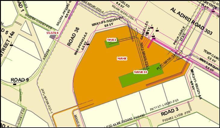
1. Introduction
To ensure the availability of power, it is essential that the load projections, the time of
power requirements and other factors from all the potential developers are available
with DEWA well in advance.
The purpose of this document is as follows:
To provide guidelines to all the major developers and the consultants in regard to
the DEWA’s power supply requirements.
To assist the developers and the consultants in understanding the requirements
for submissions of project / development Master Plan documents and to facilitate
the project / development power supply on time.
Power Supply Guidelines for Major Projects 1 of 27 Issue : Jan-2018 / Rev-5
2. Power Supply Master Plan Requirements
In order to avail the power supply for any project / development on time, it is
necessary to submit and get approved the technical pre-requisites on time as DEWA
require lead-time as indicated in Item No. 2.1.13.
2.1 Technical Requirements
The technical requirements that are necessary to be submitted to DEWA for
planning any 400/132kV and 132/11kV substations, designing the 11kV
Distribution Network and allocating necessary 11kV cables from the 132/11kV
substations are listed below:
2.1.1 Location and layout of the development project
Location (with DLTM coordinates) shall be shown on Dubai Map.
Further, a detailed project layout reflecting roads, buildings, parks,
parking areas, open spaces, water ponds / canals, bridges etc. also to be
submitted.
2.1.2 Nature of the project
Description of the project along with type of land use (Residential,
Industrial, Commercial, etc.) to be mentioned.
2.1.3 Total Connected Load & Expected Maximum Demand
Total connected load (along with split up of General & Cooling load)
of the project, type of cooling system, and expected peak demand.
Realistic power requirement date / phasing.
Split up details of the load like, Residential, Commercial, Industrial,
Cooling, etc.
Plot-wise load details in the standard format (refer to Annexure-2).
In case ultimate load details are not available, the load requirement
up to next 5 years should be submitted.
Details of the District Cooling Plant loads (size, location and the
expected phasing of its commissioning).
Power Supply Guidelines for Major Projects 2 of 27 Issue : Jan-2018 / Rev-5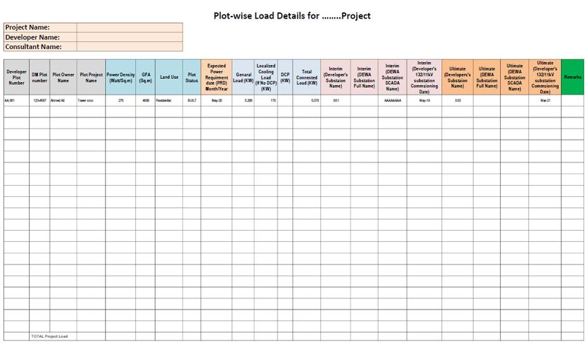
2.1.4 Distribution Renewable Resources Generation (DRRG)
For project with DRRG, the submittal shall include DRRG plan (PV
Rooftop Solar) which consists of;
Planned DRRG capacity (kW) per plot and for entire project.
Expected commissioning dates of PV solar in the project.
For more details, refer to DEWA’s DRRG standard issued on DEWA
website as shown in below link:
http://www.dewa.gov.ae/images/smartforms/DEWA_Standards_for_Di
stributed_Renewable_Resources_Generators.pdf
2.1.5 Power Factor
Power Factor is to be maintained at not less than 0.95 and any capacitor
bank installation required at customer end (at 11kV level) shall be by the
customer at his own cost.
2.1.6 Load Characteristics (quality of voltage, harmonics, flickering, dents,
etc.)
European Standard EN 50160 gives the main characteristics of the
supply voltage to be expected at customer load supply terminals.
Customers shall ensure that their equipment can adequately operate
in accordance with the supply technical characteristics included in this
Standard.
Voltage drop calculation, harmonic study, fault level calculation, etc.,
to be submitted by the consumer for any dirty load/ private
switchgear (refer to Annex-2 (page 12): Design Requirements &
Guidelines for 11kV supply.
Installation of special equipment and devices if required to maintain
the same as per the standards shall be by the consumer at his own
cost.
2.1.7 Power Supply Voltage
Dedicated / shared 132/11kV substation is required for meeting the
power supply requirement of any Major Development. Large loads
might require 400/132kV source at a voltage level of 400kV. The
project developer should allocate plots for the required number of
Power Supply Guidelines for Major Projects 3 of 27 Issue : Jan-2018 / Rev-5substations and associated corridors for necessary overhead
lines/cable circuits.
11kV shall be the general distribution voltage.
2.1.8 Substation Plot Sizes
400/132kV substation: 200m x 200m
132/11kV substation: 50m x 60m
11/0.4kV substation: Refer to Distribution Substation Guidelines.
2.1.9 Location of Substation Plot
400/132kV Substation location
The 400/132kV substation plot should have access to heavy vehicles.
Enough space/corridors for taking 400kV overhead lines IN/OUT.
Enough space/corridors for taking 132kV cables IN/OUT.
132/11kV Substation location
The 132/11kV substation plot shall have access from two major
roads or one major road and Sikka (min 7m wide). The longer side to
face the road.
Enough space/corridors for taking 132kV cables IN/OUT.
Enough space/corridor for taking out 80 numbers of 11kV outgoing
cables with proper duct arrangement with minimum 150mm space
between the cables.
Location of 132/11kV substations should be provided at the load
centre and close to District Cooling Plants (DCP) if available.
When a project requires more than one 132/11kV substation, the
feeding zone of each substation shall be specified.
2.1.10 Site Plan for 400/132kV and 132/11kV Substation
Approved site plan /affection plan (in the ownership of DEWA) of the
substation plot is required from the concerned Zoning Authority. The
developer shall confirm, whether the building permit for the substation
building will be issued by Dubai Municipality or other Authorities.
Power Supply Guidelines for Major Projects 4 of 27 Issue : Jan-2018 / Rev-52.1.11 Undertaking to Clear Services within the Substation Plot
The developer to submit an undertaking letter to clear / divert all
services within the plot allocated for the 132/11 kV substation and the
associated 132 kV and 11 kV corridors (if any), well in advance prior to
the issuance of the Project Parameter Report (PPR) and also to bear all
the associated costs by the developer.
2.1.12 Corridors
400 kV overhead lines
50m wide corridor (double circuit tower line).
132 kV underground cables
2.5m wide corridor for each 132kV cable circuit.
Minimum horizontal clearance between 132kV corridor and nearby
pressure pipeline (100mm to 450mm Ø) shall be 1m (edge of the
pipe to edge of the trough).
Minimum horizontal clearance between 132kV corridor and nearby
pressure pipeline (500mm to 1200mm Ø) shall be 3m (edge of the
pipe to edge of the trough).
Minimum gap of 2m shall be ensured between 132kV corridors and
nearest foundation / permanent structure / plot boundary.
132kV cable under the dual carriageway is not acceptable. The
surface above 132kV corridors shall be either soft landscaped or
interlock tiled only.
11 kV underground cable
Exclusively 11kV corridor of 7m (2x2.5m + 2m gap) width to be
provided at two adjacent sides of 132/11kV substations up to the
roads.
Exclusive 11kV corridors of 2.5m width to be provided on both sides
of the road around the 132/11kV substations.
A single stretch of 11kV corridor width should not exceed 2.5m.
A minimum clearance of 2m to be maintained between 11kV
corridors / 132kV and 11kV corridors.
Power Supply Guidelines for Major Projects 5 of 27 Issue : Jan-2018 / Rev-5 Dedicated 11kV corridors to be provided from the source 132/11kV
substation to the District Cooling Plant (DCP).
The 11kV corridors under carriageway, median, curbstone and service
road are not acceptable. The surface above 11kV corridors shall be
either soft landscaped or interlock tiled only.
Cross-section to be provided for each road section, dedicated 11kV
corridors should be available on both sides of road.
Duct arrangement for each road crossing is to be provided.
In case of 132/11kV substation away from the road Right–of–Way
(ROW), the party shall provide sufficient corridor from the substation
boundary to the road.
2.1.13 Policy on Construction of 400kV and 132kV substations.
400/132kV substation
DEWA requires sufficient lead time to construct a 400/132kV
substation.
132/11kV substation
Any 132/11kV substation for development projects shall be constructed
by the project developer matching their power requirement phasing of
the project, through a DEWA approved consultant and contractor.
However, DEWA requires adequate lead time for arranging 132kV cables
to any new 132kV substations after finalization of load requirements,
substation locations, cable corridors and receiving the original affection
plan of the plot for the substation in the ownership of DEWA.
2.1.14 Requirement for 11kV Network/Design Approval
Latest planning of the development (with both hard & soft copy).
11kV Substation location, refer to Distribution Substation Guideline
for approval of 11kV substations.
Total connected load, maximum demand and capacity for individual
11kV substation.
Realistic power requirement date.
Power Supply Guidelines for Major Projects 6 of 27 Issue : Jan-2018 / Rev-5 Zone-wise/phase-wise load details with respective 132/11kV
substations to be provided if the number of 132/11kV substations is
two or more.
In case of number of 132/11kV substations are more, project loads
should be allocated to respective 132/11kV substations for effective
network design (Phase wise). Also, the 132/11kV substations need
to be planned for commissioning to match the power requirement
date of projects.
District cooling loads (if any) should be located adjacent to the
related 132/11kV substation.
No source metering is allowed (metering equipment to be arranged in
the 11kV switchgear room).
11kV corridors details for all the roads within the project boundary.
Approved cross section of all the roads (with 11kV corridor indicated)
to be submitted at the time of 11kV network design request.
Generally, in case of private switchgear, approval for single line
diagram should be obtained prior to purchase.
All the distribution network design requirements and guidelines for
11kV supply shall be strictly followed in line with the latest design
guidelines of Distribution Power Division.
Power Supply Guidelines for Major Projects 7 of 27 Issue : Jan-2018 / Rev-53. Backup Power Generators for Major Projects
3.1 As per the order of His Highness Sheikh Mohammed Bin Rashid Al Maktoum,
Vice President and Prime Minister of UAE and Ruler of Dubai, all real estate
developers, companies and other relevant stakeholders must install backup
generators at major projects in Dubai.
The attached DEWA circular (Refer to Annexure-3) requires the installation of
backup power generators in major buildings and landmarks such as tourist,
commercial and cultural buildings in Dubai. This is to ensure that they will have
necessary power in emergencies for public security and safety reasons, while
also ensuring the comfort and well-being of society and the public at large.
The backup power generators should be sufficient to cover lighting, elevators,
escalators, automatic doors, surveillance cameras, alarm systems and fire and
safety equipments.
These generators must be properly maintained to ensure that they will work
when needed in an effective and timely manner, according to best safety
practices.
3.2 The real estate developers, companies and other relevant stakeholders shall
ensure and provide free access to DEWA mobile generators as appropriate.
3.3 The approval process for the implementation of backup generators for Major
Projects, shall be coordinated directly with DEWA Distribution Power Division/
Connection Services Department (at Al Hudeibah office).
Power Supply Guidelines for Major Projects 8 of 27 Issue : Jan-2018 / Rev-54. Coordination and General Requirements
4.1 The main developer shall appoint a reputed consultant to prepare the
infrastructure including power supply Master Plan of their Major Project
development, in order to avail DEWA approval.
4.2 The developers or their consultants shall submit the documents as listed in
Annexure–1 for DEWA review to Power Transmission Planning Department:
Addressed to:
Dr. Nasser Tleis
Vice President – Power Transmission Planning
Dubai Electricity and Water Authority
P O Box – 564, Dubai
Fax: 04 – 3249206
4.3 In order to schedule meetings / discussions in regard to power supply Master
Plans for Major Projects, the followings may be contacted :
Mr. Mohamed Naceur Marzouki (Senior Manager-System Planning
Tel : 04 322 2900 Email: Mohamed.Naceur@dewa.gov.ae)
Mr. Vijayan Ayappan (Dy. Manager–Planning Coordination
Tel : 04 322 2909 Email: Vijayan.Ayappan@dewa.gov.ae)
Mr. Ahammed Sadique (Sr. Engineer – Planning Coordination
Tel : 04 322 2904 Email: Ahammed.kuttiadi@dewa.gov.ae)
4.4 The listed documents shall be submitted in three sets of hard copies and 1 set
of soft copy (drawings in AutoCad/Microstation & PDF and load details in Ms
Excel format).
4.5 The details as mentioned above shall be submitted well in advance to DEWA
and got approved to avoid any delay in starting the project.
4.6 Once approved, DEWA expects that the developer will adhere to the plan and
any minor changes in the project plan, changes in phasing, etc. shall be
Power Supply Guidelines for Major Projects 9 of 27 Issue : Jan-2018 / Rev-5informed to DEWA in time and got approved. Changes on works during the
execution stage shall not be entertained.
4.7 Any power supply requirement for the project shall be from the 132/11kV
substation built for the project. The developer shall phase the developments
and accordingly the power requirements matching the commissioning schedule
of the source 132/11kV substation for the project.
4.8 During the progress of the Project, bi-annual updated information shall be
submitted by the party which shall include:
a. Energized load details till date.
b. 11kV substation approvals under process (not energized).
c. HV Building NOC load applied (not yet submitted for 11kV substations
approval) less than or more than 5MW.
d. The developer shall issue confirmation on the individual party’s loads
(who had applied for HV Building NOC) as a part of their Master Plan in
terms of magnitude and time. Load under design/approval but not
approved for HV Building NOC including the load of project shall be as
per the agreement already signed between party and developer.
e. The updated information shall be submitted by the party in area maps
indicating plot numbers, power requirement dates and comparison with
the original information received as per the approved Master Plan of the
project / development.
4.9 DEWA will not be responsible for any delay in commissioning due to any
change/ revision of loads, which might result in re-design of 11kV cable
circuits.
4.10 After approval of power supply Master Plan, the developer / consultant to
submit 7 sets of final / approved power supply Master Plan (hard & soft copy)
of the project, for DEWA records.
Power Supply Guidelines for Major Projects 10 of 27 Issue : Jan-2018 / Rev-54.11 The relevant drawings, load schedules, single line diagrams and road cross-
sections for LV distribution network approvals such as 11kV substation
locations, capacity, LV cable routes, feeder pillar locations, MDB/MCCB
capacity connected load / maximum demand / demand factor of each plot /
substation wise, voltage drop etc. shall be uploaded during on-line power
supply NOC application for the project through ‘Getting Electricity’ application
system (www.dewa.gov.ae).
4.12 On approval of power supply Master Plan, the plot owners / consultant may
apply for power supply NOC for their plot, through E-Services for “Getting
Electricity” on DEWA Website (as per normal practice), along with the main
developer’s letter confirming the load figures indicated in NOC application are
same as that in the approved project Master Plan.
4.13 On finalization of power supply Master Plan for entire or portion (Phase) of
any Major Development, the project developer / consultant to approach
concerned Zoning Authority as well as DEWA Infrastructure Information &
Permits (II&P) Department (at Al Warsan Office) to upload the project
landbase in GIS. II&P department’s requirements are listed in Annexure-4.
4.14 On finalization of power supply Master Plan for entire or portion (Phase) of
any Major Project, the project developer / consultant shall approach DEWA
Infrastructure Information & Permits (II&P) Department to upload / update
the proposed 132kV & 11kV cable ducts within the project in DEWA GIS
conduit layer. Therefore, CSV file (that contain complete ducts information
such as location (in DLTM coordinates), project name, no. of ducts, type of
ducts etc.) to be submitted to the concerned department. The guidelines and
template for the CSV file submission is enclosed (refer to Annexure-5).
4.15 The project developer / consultant to obtain design / construction NOC from
DEWA Infrastructure Information & Permits (II&P) Department during
infrastructure-design / approval / execution stage.
Power Supply Guidelines for Major Projects 11 of 27 Issue : Jan-2018 / Rev-55. Annexures
5.1 Annexure – 1
List of documents to be submitted
Sr. No. Documents Remarks
1 Key Plan showing the location and layout of the
project in Dubai Map with co-ordinates.
2 Plot-wise load details in the standard format MS Excel format
(Refer to Annexure-2)
3 Phasing
4 Nature of Load
5 Details of District Cooling Loads (location /
capacity, power requirement date etc)
6 Locations of proposed 132/11kV substation(s)
7 Locations of proposed 400/132kV substation(s)
8 400kV corridors details within the project area
9 132kV corridors details with detailed road cross-
sections
10 11kV corridors details with detailed road cross-
sections
11 11kV ducts arrangements
PV Solar requirements in terms of capacity per
12
plot
The above documents shall be submitted in form of 3 sets of Hard Copies + 1
Digital Copy
Power Supply Guidelines for Major Projects 12 of 27 Issue : Jan-2018 / Rev-55.2 Annexure-2
Standard Format for Plot-wise Load Details
Power Supply Guidelines for Major Projects 13 of 27 Issue : Jan-2018 / Rev-55.3 Annexure-3
DEWA circular regarding backup generators
Power Supply Guidelines for Major Projects 14 of 27 Issue : Jan-2018 / Rev-55.4 Annexure – 4
Infrastructure Information & Permits Department Requirements for updating
Major Project Landbase in DEWA GIS
II&P Department requires below listed in order to update Major Project Landbase in DEWA
GIS ;
1. Project Layout
2. Parcels / plots along with parcel / plot IDs.
3. DEWA ESS plots with plot IDs.
4. Road Facilities ;
Road Centre Line
Right Of Way
Dividers (Road medians / roundabouts)
Road Cross-sections
Approved corridors with clear indications of width from ROW.
Layer features are given below ;
LANDBASE DATA LAYERS
S.N. Layer Name Description Geometry
Type
1 Project Boundary The entire / phase of the project Polygon
2 Parcel / plots The plot boundary as designed / approved Polygon
by the developer and issued to individual
owner.
3 DEWA ESS plot The plots designed/approved by the
developer for the purpose of building DEWA
11kV substations
4 Utility corridor The area allotted by developer within the Polygon
ROW for accommodating DEWA utilities.
5 Road_centre line Single Carriageway : A line representing the Line
physical centre of the roadway between
road shoulders.
Dual Carriageway : A line representing the
physical centre of the roadway between
road shoulder and median (road divider).
6 Sikka / Alley Represents a small road between buildings Line
and generally connect two parallel streets /
roads (usually less than or equal to 20 ft
width)
Power Supply Guidelines for Major Projects 15 of 27 Issue : Jan-2018 / Rev-57 Road_Island Non-pedestrian islands in the road surface, Polygon
such as centre island, roundabout etc. that
normally contains grass, trees, flowers or
other plantations.
8 Road_Median The area which separates opposing lanes of Polygon
traffic on divided roadways. It is also called
as central reservation or divider.
9 Right-Of-Way The land on which the roadway and its Polygon
associated facilities and appurtenances are
located. Highway ROW accommodates the
entire roadway (i.e. carriageway and
shoulders), as well as adjacent sidewalks and
the roadside corridors on which utilities are
located.
10 Pavements A path consisting of a paved area on the Polygon
side of a road for pedestrians, it is also
called a sidewalk.
11 Building / The outline of a building. Distances from the Line
Property Line ends and / or sides of the lot beyond which
construction may not extend.
12 Parking Space Vehicle parking lot boundaries Polygon
Data formats : The format of the data may be any common GIS format such as Shape file,
ESRI Geodatabase or a common CAD format such as AutoCAD Drawing File (DWG) or
MicroStation Design File (DGN). However, road cross0-sections must be provided in CAD
/ DGN formats only.
If the Data is unable to provide in ESRI shape file format, below are few guidelines should
be followed when preparing CAD / DGN data for submission to DEWA.
Each Feature class (Layer) and / or its sub-types need to be in a separate layer/level in the
CAD / DGN file.
o Each CAD layer / level must represent only one class of feature.
o Each text representing information about plot/road/etc and should fit well inside it.
o All data attributes (tabular data) for a corresponding CAD ID will be also be found
and documented in an associated MS Excel spreadsheet. A worksheet for each CAD
layer will be created. The worksheet should contain the CAD ID (ex: handle which
must be unique) and one or more fields that contain the associated attribute data.
Power Supply Guidelines for Major Projects 16 of 27 Issue : Jan-2018 / Rev-5Topological Rules :
o Ellipse and Spline shall not be used at all.
o Overlapping, self-intersecting and zero length are not allowed.
o Where two polylines logically join, intersecting features within the same layer these
shall be snapped at the point of intersection.
o Lines should run continuously from Point object to Point object. All line features
shall be of a continuous line-type, such that each individual line feature (i.e each
segment) is only broken at the ends where a node/structure is located.
o Lines should not be broken for the purpose of annotations. Annotation for each
layer shall be placed in annotation layers as specified in the template file.
o Straight lines must be represented by only the beginning and ending x- and y-
coordinate points. The exception to this is a line where the coordinates differ only in
the z values (ex: developed from multiple traverses on the same bearing). Lines
stings must not cross back on themselves or have a zero length (i.e points).
o Polyline features that logically join shall be snapped to each other at the joining
ends. This is, no dangles (overshoots and undershoots) are allowed.
o All polyline features shall be created as closed polylines.
o All edges on polygon features must be snapped together at the vertices. Gap in
polygon boundaries will not be accepted.
o Polygon features in the same layer cannot overlap each other.
o The completed CAD drawing file should contain text in standard fonts that can be
read without third-party software.
Coordinate System : Features in DEWA GDS compliant files must be represented in
real world locations as referenced by Dubai Local Transverse Mercator Projection
(DTLM) parameters as given below :
Projection :
Transverse Mercator
Parameters :
Longitude of Origin 55:20:00:00 d:m:s
Latitude of Origin 0:00:00:000 d:m:s
False Easting 500,000.000 m
False Northing 0.000 m
Power Supply Guidelines for Major Projects 17 of 27 Issue : Jan-2018 / Rev-5Scale Factor along Longitude of Origin 1.0000 Geodetic Datum: WGS84 Ellipsoid WGS84 (standard parameters) Equatorial Radius: 6378137.000 m Polar Radius: 6356752.314 m Eccentricity: 0.0818191908426215 Flattening: 0.00335281066474746 Flattening Inverse: 298.257223563002 Units and Formats : Geographic Units: d:m:s Format: Long/lat. Precision: 4, Positive N,E Projection Units: m Format: Easting/Northing Precision: 3 Height Units: m Precision: 3 Geocentric Units: m Precision: 3 Distance Units : m Precision: 3 Angular Units: deg Precision: 6 Power Supply Guidelines for Major Projects 18 of 27 Issue : Jan-2018 / Rev-5
5.5 Annexure – 5
Infrastructure Information & Permits Department Requirements for updating
Proposed Ducts within Major Project Landbase in DEWA GIS

                  Digital Drawing Submission Requirements
                                             For
                                   Conduit System

Power Supply Guidelines for Major Projects         19 of 27   Issue : Jan-2018 / Rev-5
Index :
1. Introduction
2. General Requirements
2.1 Documentation
2.2 Co-ordinate System
2.3 Accuracy of co-ordinates in Digital Drawings
2.4 Digital Drawing Format Standards
2.5 Map Orientation
2.6 2D Versus 3D drawings
3. Digital standards for Electricity Conduit System
3.1 Requirements for Data Delivered in ESRI Shape Format
3.2 Requirements for Data Delivered in CAD (DGN/DXF/DWG) Format
3.2.1 General Requirements
Appendix 1, Specification of Coded Values for Various Fields
Subtype
State
Type of Duct
Encasement Type
Duct Size
Duct Number
Appendix 2, Sample CSV File Template
1. Introduction
DEWA requires drawings to be submitted in standardized digital format. This will enable
DEWA to process the applications more efficiently. The intent is that the required
hardcopy and digital submission be produced from the same digital source without
significant modification. The hardcopy maps will continue to be the official documents.
This document describes the standards to be followed when submitting digital drawings to
DEWA. Any questions concerning these standards or exceptions to these standards due to
special circumstances should be referred to DEWA IT Department for further clarification.
Power Supply Guidelines for Major Projects 20 of 27 Issue : Jan-2018 / Rev-52. General requirements
All digital drawings submitted to DEWA must confirm to the following requirements.
2.1 Documentation
The following documentation is required when submitting digital drawings to DEWA
Document describing the content of digital data, including project details. Example:
Project Name: Palm Island
File Name(s): 132kV_ThePalm.shp, 33kV_ThePalm.shp, etc
Date: July 1, 2004
Company Name: Contractor LLC
Contact Person: John Doe
Contact Phone: +971 50 555 5555
Contact E-mail: John.Doe@contractor.co.ae
Format: SHP/DWG2000/DXF/DGNv7
Layers submitted: Layer1, 2,3,6,23,25,34
Thumbnail images of drawings
Digital drawing files (ESRI Shapefiles/DGN/DWG/DXF files)
Comma Delimited File (CSV) sheet describing attributes of features included in
the CAD drawings. This document is not required if digital drawing is submitted in
ESRI shapefile format.
All documentation, including drawings, shall be submitted on CD-ROM media only.
2.2 Co-ordinate System
All drawings co-ordinates must be projected using the Dubai Local Transverse
Mercator projection (DLTM).
Projection:
Transverse Mercator
Parameters:
Longitude of Origin 55:20:00:00 d:m:s
Latitude of Origin 0:00:00.000 d:m:s
False Easting 500,000.000 m
False Northing 0.000 m
Scale Factor along Longitude of Origin 1.0000
Geodetic Datum: WGS84
Ellipsoid WGS84 (Standard parameters)
Equatorial Radius: 6378137.000 m
Power Supply Guidelines for Major Projects 21 of 27 Issue : Jan-2018 / Rev-5Polar Radius: 6356752.314 m
Eccentricity: 0.0818191908426215
Flattening: 0.00335281066474746
Flattening Inverse: 298.257223563002
Units and Formats:
Geographic Units: d:m:s
Format: Long/lat. Precision: 4, Positive N,E
Projection Units: m
Format: Easting/Northing Precision: 3
Height Units: m Precision: 3
Geocentric Units: m Precision: 3
Distance Units: m Precision: 3
Angular Units: deg Precision: 6
2.3 Accuracy of co-ordinates in digital drawings
The accuracy of the co-ordinates submitted to DEWA shall be clearly mentioned on
the submitted drawings or in attached documentation.
2.4 Digital drawing format standards
All drawing submitted to DEWA must be delivered in one of the following standardized
drawing formats
Preferred drawing format by DEWA
ESRI Shape files (*.shp) are preferred by DEWA
Trial-pit details containing cross-section drawings shall be submitted in any CAD
format as specified below.
Other acceptable drawing formats
MicroStation design files (.dgn) up to Version 7
AutoCAD drawing files (.dwg) up to AutoCAD 2000
ASCII, binary and partial drawing interchange files (.dxf) that comply with DXF
standards
2.5 Map Orientation
All drawings shall be delivered in a non-rotated orientation (North facing up).
2.6 2D versus 3D drawings
All drawings are to be submitted as two dimensional (2D) graphic files. Three-
dimensional Drawings are not acceptable except if specified by DEWA.
Power Supply Guidelines for Major Projects 22 of 27 Issue : Jan-2018 / Rev-53. Digital standards for Electricity Conduit System
The following standards shall be followed when submitting Electricity Conduit System
Drawings.
3.1. Requirements for data delivered in ESRI Shape format
The following shape files shall be delivered, whichever are applicable:
FeatureClass Shape
Subtype Attributes
(Layername) (Featuretype)
Conduit System Polyline 1-Duct Bank,
DuctType, NumDuct,
2-Trench,
Depth, NoOccupied.
3-Truf
Other attributes to be present in all the above-mentioned ESRI shape files:
Subtype (Containing Subtype value as mentioned in Subtype column)
State
Created by (Supplier of drawing)
Creation Date
Modified By
Modification Date
Consultant / Contractor Name
Project Name
Contract number
Description
Duct size
Material
Number of ducts
Type of duct
Remarks (if any)
Subtype, State, Duct Size, Material, Number of Ducts and Type of ducts shall be
entered as coded values as listed in appendix 1.
ESRI Shape file templates can be delivered as and when requested for.
Power Supply Guidelines for Major Projects 23 of 27 Issue : Jan-2018 / Rev-53.2. Requirements for data delivered in CAD (DGN/DXF/DWG) format
The following specification shall be applicable for CAD drawings:
3.2.1 General Requirements
New Conduits should be placed as Lines on Layer 48. Ducts should be labeled with
Duct Type and State on the CAD file.
All new Conduits (Line features) must be clearly distinguishable from existing
features by symbology and labels (Existing/New/Proposed).
For each feature the following spatial data is required: StartPoint, EndPoint and
TurningPoints if applicable). Features must have x,y co-ordinates as label text near
the respective location on the drawing. These co-ordinates shall be on level 10.
All drawings delivered to DEWA shall have an attached CSV file containing all
features, their X,Y location (StartPoint, EndPoint and TurningPoints) and shall
include attributes (same attributes as mentioned in 2) specified in a tabular
form. Sample CSV template available in Appendix 2. Subtype, State, Duct Size,
Material, Number of Ducts and Type of ducts shall be entered as coded values as
listed in appendix 1
An additional reference number can be added (if required) to enable relationships
between the graphics in CAD and attributes in CSV.
Trial-pit details containing cross-section drawings shall include XY co-ordinates;
direction of cross section view; Z coordinates relative to sea level and ground.
Power Supply Guidelines for Major Projects 24 of 27 Issue : Jan-2018 / Rev-5Appendix 1, Specification of coded values for various fields Subtype Code State 1 Duct Bank 2 Trench 3 Turf State Code State 2 Proposed 3 Cancelled 4 In service 5 Approved for Construction 6 Constructed/As laid Type of Duct Code Conduit Nominal Voltage 5 132kV 26 33-11kV 27 LV Encasement Type Code Encasement Type BF Back Fill CCRT Concrete UNK Unknown Duct Size Code Duct Size 2 2” 4 4” 6 6” 12 12” 18 18” 24 24” 30 30” 36 36” 42 42” 48 48” Power Supply Guidelines for Major Projects 25 of 27 Issue : Jan-2018 / Rev-5
Duct Number
Code       Actual value    Code       Actual value     Code    Actual value
    2       UNKNOWN           14              3x6         41        19
    4            1            11              6x4         42        20
    5            2            15              10          43        21
    6            3            26              2x5         44        22
    7            4            27             2x15         45        23
   16           16            28             2x24         46        25
   17            6            29             2x10         47        26
    9           18            30             2x20         48        27
   24            5            31             2x25         49        28
   25            7            32             2x30         50        29
    1          IV(1)          33             2x35         51        30
    3          IV(3)          34             2x40         40        4x4
   39         IV(39)          35             2x45         21       3x16
   12           1x6           36             2x50         19        2x8
    8           2x4           23             3x12         20       2x12
   13           2x6           22              3x8         37        11
   10           3x4           38              13

Power Supply Guidelines for Major Projects          26 of 27   Issue : Jan-2018 / Rev-5
Appendix 2, Sample CSV File Template
RefNo 1 2 3
X1 561938.4 500020 500400
Y1 2751476 2785460 2770000
X2 562382.3 500010.1 500600.1
Y2 2751237 2785480 2770100
X3 500030.5
Y3 2770000
X4 500061
Y4 2770080
SubtypeCD 1 1 1
State 2 4 5
Consultant_Name_M Parsons Parsons Parsons
contd…
Number No of Encas
Duct_ Type_of
Contract_number_M Material _ducts_ Ducts ement Remarks
size_F _duct_F
F Used Type
MSD1/419/DM1/022 4 uPVC 8 27 BF
MSD1/419/DM1/022 12 uPVC 9 5 UNK
MSD1/419/DM1/022 6 uPVC 10 26 CCRT
Power Supply Guidelines for Major Projects 27 of 27 Issue : Jan-2018 / Rev-5You can also read