PRISM 300W to 2kW Fiber Lasers - Operator's Manual - SPI Lasers
←
→
Page content transcription
If your browser does not render page correctly, please read the page content below
Prism Fiber Lasers

PRISM 300W to 2kW
Fiber Lasers
Operator's Manual
Prism Fiber Lasers

 Safety Notes
 These safety notes indicate potential hazards associated with this PRISM Fiber Laser and the
 probable consequences of not avoiding them. Directions on the safe use of this Laser are
 provided in the remainder of these instructions for use, particularly Sections 3 Health and
 Safety, 7 Installation, and 8 Operating Instructions.
 Throughout these Instructions for Use warning messages are given in contexts in which a
 hazard may occur.

 General Hazard Information

                       WARNING: Ensure that all Users are fully aware of all safety
                       implications identified in these Instructions for Use before
                       attempting to install, operate or maintain this Laser.

                       WARNING: Attempts to modify or alter this PRISM Fiber Laser or
                       the use of controls or adjustments or performance of procedures
                       other than those specified in these Instructions for Use may render
                       this Laser unsafe.

 Attempts to modify or alter this Laser or the use of controls or adjustments or performance of
 procedures other than those specified in these Instructions for Use additionally will invalidate
 the warranty and may result in patent infringement.

 Laser Integrators are not authorised to modify this Laser.

Trumpf Laser UK Ltd.           SM-S01076                Revision A          Jan 2021                2
Commercial in Confidence       300W to 2.0kW Module Fiber Lasers Instructions for Use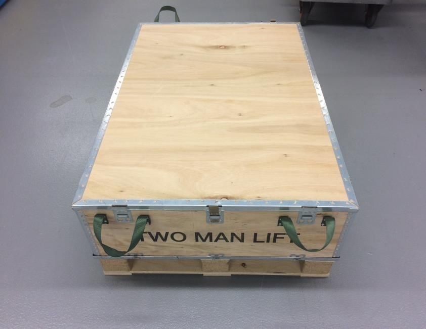
Prism Fiber Lasers

 Laser Hazard Information
                       WARNING: The output aperture of this PRISM Fiber Laser may
                       emit both invisible and visible laser radiation.
                       The invisible laser radiation will be Class 4 laser radiation. The
                       invisible radiation can be up to approximately 115% of rated power
                       CW in normal operation and 150% with a single fault. The
                       wavelength of this invisible radiation is in the range 1050-1250nm.
                       Additionally, this Laser contains embedded lasers that emit invisible
                       laser radiation up to approximately 170% of rated power CW in
                       normal operation and 250% CW with a single fault. The wavelength
                       of this invisible radiation is in the range 900-1000nm.
                       AVOID EYE OR SKIN EXPOSURE TO DIRECT OR SCATTERED
                                            RADIATION.
                       Contact with direct or scattered laser radiation can cause damage
                       to the eyes, burn human tissue and start fires.
                       The optical connector shall be mounted in a protective housing
                       which prevents human access to laser radiation (including errant
                       radiation) in excess of the AEL for class 1, for example a housing
                       meeting the requirements of EN 60825-4.
                       WARNING: The output aperture of this PRISM Fiber Laser may
                       emit both invisible and visible laser radiation.
                       The visible laser radiation is below the Accessible Emission Limit
                       (AEL) for a Class 2 laser. The wavelength of the visible laser
                       radiation is in the range 630 – 680nm.
                                          DO NOT STARE INTO BEAM.
                       WARNING: This PRISM Fiber Laser must only be operated when
                       the optical connector is mounted in an appropriate receiver.
                       Care must be taken to prevent the electrical contacts on the optical
                       connector being accidentally connected. Do not place the optical
                       connector on a metal surface.
                       The protective cap must be placed over the connector whenever
                       the connector is not in a receiver.

                       WARNING: Before carrying out any maintenance task detailed in
                       these Instructions for Use ensure that power to the Laser is
                       disconnected. Failure to do so may lead to serious personal injury.

Trumpf Laser UK Ltd.          SM-S01076                Revision A          Jan 2021            3
Commercial in Confidence      300W to 2.0kW Module Fiber Lasers Instructions for Use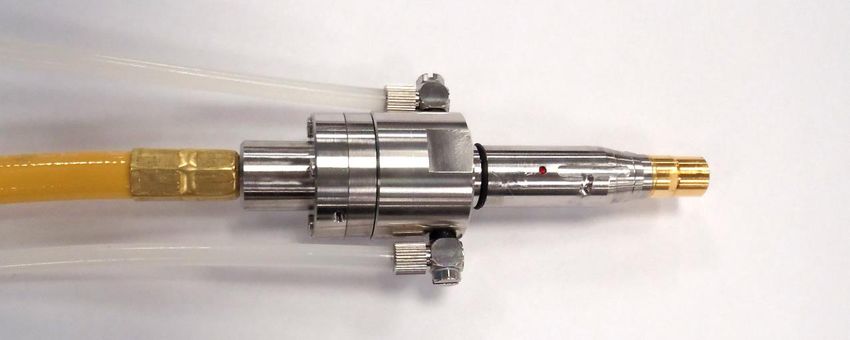
Prism Fiber Lasers

                       WARNING: This PRISM Fiber Laser does not control the pump
                       power supply and has no safety function to de-energise or control
                       the pump diodes or the output power.
                       Failure to provide external safety systems may result in exposure to
                       harmful levels of radiation.

 Electrical Hazard Information
                       CAUTION: This PRISM Fiber Laser must be grounded for safety
                       and to comply with regional electrical codes.
                       Failure to do so may result in electric shock and incorrect operation
                       of the Laser.

 Weight Hazard Information
                       CAUTION: This PRISM Fiber Laser is heavy and so precautions
                       must be taken when lifting and moving.
                       Failure to do so may cause serious injury.

 Pressure Hazard Information
                       CAUTION: Ensure an approved overpressure safety device
                       compliant with ISO4126-1 (or equivalent) is installed when
                       connecting the PRISM Fiber Laser to an external chiller or factory
                       water supply.
                       Failure to do so may result in water leaks and damage to the Laser
                       and auxiliary equipment.

 Laser for Incorporation
                       CAUTION: This PRISM Fiber Laser is specifically designed to be a
                       laser for incorporation or integration into other equipment. As such,
                       it is not required to, and does not, meet the requirements for a
                       stand-alone laser system as defined by IEC/EN 60825-1.

Trumpf Laser UK Ltd.          SM-S01076                Revision A          Jan 2021            4
Commercial in Confidence      300W to 2.0kW Module Fiber Lasers Instructions for Use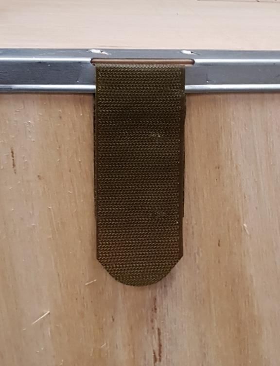
Prism Fiber Lasers
CONTENTS
1 Structure and Scope of Instructions for Use 9
2 Definition of Symbols and Terms 10
3 Health and Safety 12
3.1 General 12
3.2 Intended Use of the PRISM Fiber Laser 13
3.3 Hazards 13
3.4 Compliance 15
3.5 Labelling 18
4 Document References 20
5 PRISM Tour 21
5.1 Key Parts 21
5.2 Key Features 22
5.3 Auxiliary Equipment 26
5.4 Configuration Software Tools 27
5.5 Explanation of Order Codes 28
6 Getting Started 30
6.1 Receiving and Inspection 30
6.2 Unpacking and Handling 30
6.3 Unpacking the Beam Delivery Optic 33
7 Installation 34
7.1 Safety and Compliance During Installation 34
7.2 Location and Environment 34
7.3 Mounting 35
7.4 PRISM Fiber Lasers with Bare Fiber Output 35
7.5 Cooling Water Connections 36
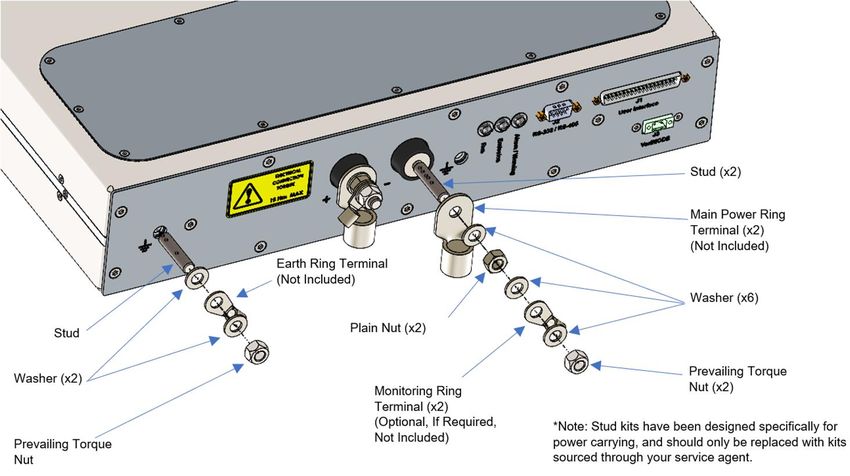
7.6 Electrical Connections 40
7.7 Routing the Beam Delivery Optic 50
7.8 Connecting and Removing the PIPA-Q Optical Connector to the Process Head 50
8 Operating Instructions 52
8.1 Before Operation 52
8.2 Modes of Operation 53
8.3 Turning the Laser On and Off 55
8.4 Turning the Alignment Laser On and Off 59
8.5 Monitoring, Alarms and Diagnostics 59
8.6 Laser Control 62
8.7 Serial Control of the Laser Using PrismView 63
8.8 Serial Control of the Laser Using FiberView 63
9 Maintenance 64
9.1 Periodic Inspection 64
9.2 General Cleaning 64
Trumpf Laser UK Ltd. SM-S01076 Revision A Jan 2021 5
Commercial in Confidence 300W to 2.0kW Module Fiber Lasers Instructions for Use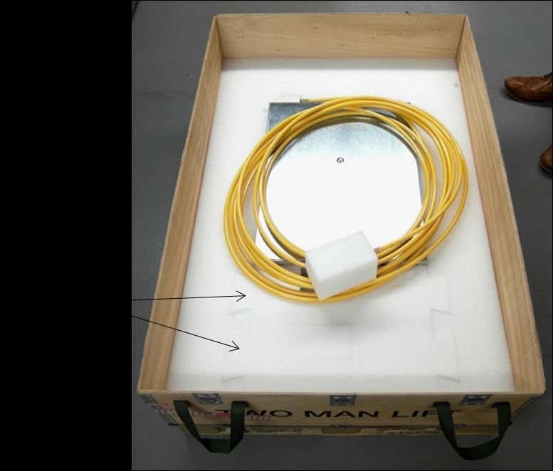
Prism Fiber Lasers

                   9.3       Maintenance of Optics                                                                                              64

 10                Disposal                                                                                                                     65
 11                Specifications                                                                                                               66
                   11.1      Operating Conditions                                                                                               66
                   11.2      Non-Operating Conditions                                                                                           68
                   11.3      Utility Requirements                                                                                               68
                   11.4      Optical Specifications                                                                                             74
                   11.5      Mechanical Specifications                                                                                          79

 12                General Information                                                                                                          88
                   12.1      Trade Marks                                                                                                        88
                   12.2      Licensing                                                                                                          88
                   12.3      Software                                                                                                           88
                   12.4      Warranties                                                                                                         88
                   12.5      Copyright                                                                                                          88
                   12.6      Changes                                                                                                            88

 13                Contact Information                                                                                                          89
 14                Customer Service                                                                                                             90

 FIGURES
 Figure 1 WEEE Symbol ........................................................................................................................... 15
 Figure 2 PRISM Fiber Laser with Optical Connector Key Parts .............................................................. 21
 Figure 3 PRISM Fiber Laser Key Features ............................................................................................. 22
 Figure 4 PIPA-Q Optical Connector with Protection Against Back-Reflection ........................................ 24
 Figure 5 PRISM Fiber Laser with Auxiliary Equipment ........................................................................... 26
 Figure 6 PrismView GUI ............................................................................ Error! Bookmark not defined.
 Figure 7 Laser in Crate as Received ....................................................................................................... 30
 Figure 8 Removing Fastener ................................................................................................................... 31
 Figure 9 Crate without Lid and Top Layer of Foam Packaging ............................................................... 31
 Figure 10 Lift BDO to Enable the Next Layer of Packaging to be Removed .......................................... 32
 Figure 11 BDO Replaced ........................................................................................................................ 32
 Figure 12 Lifting Laser from Crate ........................................................................................................... 33
 Figure 13 Cooling Water Connections .................................................................................................... 36
 Figure 14 2 pipe module integration to 4 pipe system ............................................................................ 39
 Figure 15 Electrical Connections and Status Indicators .......................................................................... 41
 Figure 16 Star Earthing Configuration ..................................................................................................... 43
 Figure 17 Bus Bar Connection ................................................................................................................ 44

Trumpf Laser UK Ltd.                          SM-S01076                             Revision A                   Jan 2021                              6
Commercial in Confidence                      300W to 2.0kW Module Fiber Lasers Instructions for Use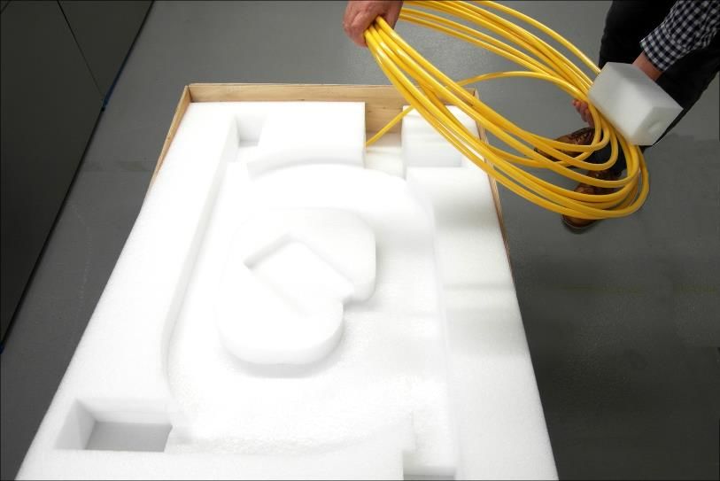
Prism Fiber Lasers

 Figure 18 User Interface Connector ........................................................................................................ 44
 Figure 19 PLC Logic Levels .................................................................................................................... 45
 Figure 20 TTL Logic Levels ..................................................................................................................... 45
 Figure 21 RS-232 and RS-485 Connector .............................................................................................. 48
 Figure 21 Timing Diagram for CW Operation .......................................................................................... 56
 Figure 22 Timing Diagram for Operation in Analogue Modulation Mode ................................................ 57
 Figure 23 Timing Diagram for Operation in Digital Modulation Mode ..................................................... 58
 Figure 24 Environmental Conditions for Non-Condensing Operation ..................................................... 67
 Figure 25 Minimum Flow Rate against Inlet Water Temperature ............................................................ 73
 Figure 26 Modulation Bandwidth as a Function of Set Power ................................................................ 76
 Figure 27 Outline Drawing – Short Module ............................................................................................. 80
 Figure 28 Outline Drawing – Long Module .............................................................................................. 82
 Figure 29 PIPA-Q Optical connector ....................................................................................................... 83
 Figure 30 Outline Drawing – PIPA-Q Beam Delivery Optic .................................................................... 84
 Figure 31 Installation Drawing of 10.5µm - 40mm Focal Length ............................................................ 85
 Figure 32 Installation Drawing of 20µm - 60mm Focal Length ............................................................... 85
 Figure 33 Outline Drawing – Bare Fiber Output ...................................................................................... 86

Trumpf Laser UK Ltd.                          SM-S01076                             Revision A                   Jan 2021                              7
Commercial in Confidence                      300W to 2.0kW Module Fiber Lasers Instructions for Use
Prism Fiber Lasers

 TABLES
 Table 1 Safety, Explanatory and Compliance Labels ............................................................................. 18
 Table 2 Information Labels ...................................................................................................................... 19
 Table 3 Order Codes ............................................................................................................................... 28
 Table 4 Order Code Detail ....................................................................................................................... 28
 Table 3 Water Tubing and Fittings .......................................................................................................... 37
 Table 4 Integration fitting ......................................................................................................................... 39
 Table 5 Electrical Interface Connections ................................................................................................. 41
 Table 6 Pinout of User Interface Connector ............................................................................................ 46
 Table 7 RS-232 and RS-485 Control ...................................................................................................... 49
 Table 8 Meaning of Status Words ........................................................................................................... 60
 Table 9 Laser Control Interfaces ............................................................................................................. 62
 Table 10 Environmental Operating Conditions........................................................................................ 66
 Table 11 Non-Operating Conditions ........................................................................................................ 68
 Table 12 Electrical Requirements ........................................................................................................... 68
 Table 13 Power Supply Output Capability Requirements ....................................................................... 70
 Table 14 Cooling Water Requirements ................................................................................................... 71
 Table 15 Cooling Requirements (Base Plate) ......................................................................................... 72
 Table 16 Cooling Requirements (PIPA-Q Optical Connector) ................................................................ 73
 Table 17 Laser Optical Specifications – Output Power Dependent ....................................................... 74
 Table 18 Non power related Laser Optical Specifications – Output Power Independent ....................... 75
 Table 19 Maximum Modulation Bandwidth ............................................................................................. 76
 Table 20 Mechanical Specifications – Short Modules ............................................................................. 79
 Table 21 Mechanical Specifications – Long Modules ............................................................................. 81
 Table 22 Mechanical Specifications – PIPA-Q Optical Connector .......................................................... 83
 Table 23 PIPA-C Optical Connector Specifications ................................................................................ 85
 Table 24 Bare Fiber Output Interface ...................................................................................................... 87
 Table 25 Contact Information .................................................................................................................. 89

Trumpf Laser UK Ltd.                           SM-S01076                               Revision A                    Jan 2021                               8
Commercial in Confidence                       300W to 2.0kW Module Fiber Lasers Instructions for Use
Prism Fiber Lasers

 1 Structure and Scope of Instructions for Use
 These Instructions for Use for OEM PRISM Fiber Laser Modules contain all the information that
 Users need to know for their safe and efficient use. This information is important. These
 Instructions for Use must be read before installing and using the Laser and made available for
 reference at the location where the Laser is being used. Additional or replacement copies are
 available from Trumpf Laser UK Ltd.
 These Instructions for Use are divided into the sections below which provide Users with health
 and safety information before introducing the Laser and then guiding them through its
 installation, operation, maintenance and disposal. Lastly, they provide other useful information
 and the Lasers’ specifications.

                         1    Structure and scope of instructions for use
                         2    Definition of Symbols and Terms
                         3    Health and Safety
                         4    Document References
                         5    PRISM Tour
                         6    Getting Started
                         7    Installation
                         8    Operating Instructions
                         9    Maintenance
                         10   Disposal
                         11   Specifications
                         12   General Information
                         13   Contact Information
                         14   Customer Service

 The PRISM Fiber Laser variants covered by these Instructions for Use have order codes:

  SP -      0300       - M - W -      014     - 02 -     FBR      - 0 1 0 - 00 0 - 0 0       3
            0500                      020       05       FB2            E      1 1           4
            0750                      050       10       PIQ            F      4             5
            1000                      100       15       PQC
            1500                      200       20
            2000                      300       30

 The order code can be found on a label on the rear panel of the Laser.
 Details of the options shown in bold are expanded in Section 5.5 below.

Trumpf Laser UK Ltd.           SM-S01076                Revision A          Jan 2021                9
Commercial in Confidence       300W to 2.0kW Module Fiber Lasers Instructions for Use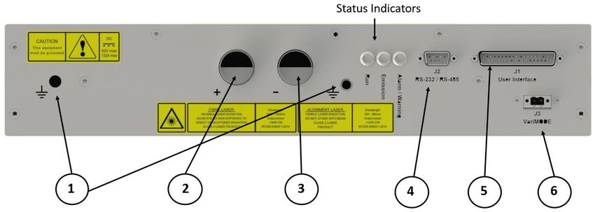
Prism Fiber Lasers

 2 Definition of Symbols and Terms

                           This symbol alerts the user to the hazard of exposure to laser
                           radiation.

                           This symbol alerts the user to the hazard of exposure to
                           electricity.

                           This symbol alerts the user to the hazard caused by the weight
                           of this Laser.

                           This general warning symbol emphasises important information
                           needed during installation and operation.

                           This symbol identifies the protective conductor terminal (ground
                           point).

     WARNING:              Indicates a hazard with a medium level of risk which, if not
                           avoided, could result in death or serious injury.
                           Warnings must be observed to prevent personal injury to
                           yourself and others.
     CAUTION:              Indicates a hazard with a low level of risk which, if not avoided,
                           could result in minor or moderate injury.
                           Cautions must be observed to prevent personal injury and
                           damage to or destruction of equipment or loss of operational
                           effectiveness.

Trumpf Laser UK Ltd.         SM-S01076                Revision A          Jan 2021              10
Commercial in Confidence     300W to 2.0kW Module Fiber Lasers Instructions for Use
Prism Fiber Lasers
PRISM Fiber PRISM Fiber Laser and Laser as used herein means the item
Laser and Laser: that was procured from Trumpf Laser UK Ltd.
The PRISM Fiber Laser is a complete fiber laser system. By
‘complete’ it is meant a laser system as sold and ready for use
for its intended purpose without modifications to the
specification of the product.
The PRISM Fiber Laser is specifically designed to be a laser
for incorporation or integration into other equipment. As such, it
does not meet the full requirements for a stand-alone laser
system as defined by 21 CFR 1040.10 and IEC/EN 60825-1.
The PRISM Fiber Laser is not a consumer product and is not to
be sold on or made available as such.
Laser Integrator: Any person who integrates the Laser into equipment, or any
person who uses the Laser in the form as supplied by Trumpf
Laser UK Ltd.
User: Individuals or organizations that use the Laser. User includes
the Laser Integrator and the end user.
Authorised Those who have attended official Training Courses and have
Personnel: been certified as competent.
OEM: Original Equipment Manufacturer. A company or organisation
which is skilled in and understands the integration issues
surrounding the use, design and supply of laser products to
end users in the end markets which it supplies.
Trumpf Laser UK: Trumpf Laser UK Ltd.
Trumpf Laser UK Ltd. SM-S01076 Revision A Jan 2021 11
Commercial in Confidence 300W to 2.0kW Module Fiber Lasers Instructions for UsePrism Fiber Lasers 3 Health and Safety 3.1 General This section gives information on the hazards which may be encountered during installation, operation and maintenance of this PRISM Fiber Laser and steps to reduce the risk. Also included is information on laser and electrical safety compliance. All safety instructions including the instructions mentioned in other sections of these Instructions for Use must be followed. Not following safety instructions may constitute a hazard to Users and third parties or cause damage to property and the Laser. Only Authorised Personnel who have been instructed in, and fully understand, the necessary safety procedures should use this laser. Access to the laser must be restricted to Authorised Personnel. Any local safety requirements for the operation of this equipment must be complied with. Throughout the documentation, ‘WARNING’, and ‘CAUTION’ paragraphs appear. It is the responsibility and duty of all Users who operate and maintain this equipment to fully understand the WARNING and CAUTION and act in order to reduce or eliminate hazards. Trumpf Laser UK Ltd. SM-S01076 Revision A Jan 2021 12 Commercial in Confidence 300W to 2.0kW Module Fiber Lasers Instructions for Use
Prism Fiber Lasers

 3.2         Intended Use of the PRISM Fiber Laser
 This Laser has been designed exclusively for incorporation or integration into other equipment
 for processing:
     •   solid metals, including metal alloys and metal powders
     •   ceramics in both solid and powder form
     •   composite materials
 Operating the device within the limits of its designated use requires the user to:
     •   observe the instructions set out in these Instructions for Use
     •   install and use this Laser in compliance with international, national and local regulations
         regarding laser safety, for example IEC/EN 60825-1 and 21 CFR 1040.10.
     •   install and use this Laser in compliance with international, national and local regulations
         regarding the safety of electrical equipment, for example BS EN 60204
     •   wire and connect the electrical lines to this Laser in compliance with international,
         national and local regulations regarding electromagnetic compatibility (EMC), for
         example the relevant sections of IEC/EN 61000 and FCC CFR47
     •   not move this Laser when it is switched on (except that the optical connector may be
         moved provided that the bending limits of the conduit are observed)
     •   carry out necessary inspection and maintenance work
 This Laser is not intended:
     •   for processing in connection with flammable or explosive materials
     •   for use in an explosion prone environment
 Trumpf Laser UK cannot be held liable for any damage resulting from such use. The risk lies
 entirely with the User.

 3.3         Hazards
 3.3.1 Laser Hazards

 All Warnings, including those in the Safety Notes and those in other sections of these
 Instructions for Use, must be heeded.
 Laser emissions from the housing of the Laser and the conduit of the beam delivery optic are
 less than the AEL for Class 1 of IEC/EN 60825-1 with a single fault providing that the Fiber
 Continuity Monitoring System (FCMS) is correctly implemented by the Laser Integrator.

Trumpf Laser UK Ltd.           SM-S01076                 Revision A         Jan 2021              13
Commercial in Confidence       300W to 2.0kW Module Fiber Lasers Instructions for Use
Prism Fiber Lasers
WARNING: Care must be taken especially when controlling this
PRISM Fiber Laser remotely across a network.
Failure to do so could result in another User being exposed to
hazardous levels of radiation.
It is the responsibility of the Laser Integrator to ensure that when
controlled remotely no hazardous levels of radiation are emitted
when unsafe to do so.
3.3.2 Thermal Hazard
This Laser is designed to be used in a 19” rack cabinet or other housing which prevents access
to surfaces which may get hot during operation.
3.3.3 Materials Processing Hazards
Materials processing can generate vapour, fumes, solid particulates and other air contaminants
that may irritate, be toxic, or even fatal. It is the responsibility of the user to ensure that all
relevant safety precautions are followed and that any legal requirements are adhered to in
accordance with local legislation. It is advised that Material Safety Data Sheets (MSDS) for any
material to be processed are evaluated and that adequate measures for fume extraction and
venting are considered. Interaction of the beam with certain materials can cause potentially
harmful levels of visible radiation to be emitted. Appropriate protective measures must be taken.
CAUTION: It is essential that any debris associated with laser
processing is removed and cleaned away on a regular basis.
Failure to do so may result in fire.
3.3.4 Other Hazards
While most of the hazard comes from laser radiation, there are certain non-beam hazards that
are often associated with use of laser systems. The Laser requires an electrical supply and is
water-cooled. Electricity and water, individually or in combination, may create hazards.
It is recommended that the Laser should be installed sufficiently far above the floor to reduce
the risk from electricity in the case of flooding: at least 250mm is recommended.
Mechanical hazards may include moving parts in cutting, welding and material handling
systems.
High temperatures and fire hazards may also result from the operation of Class 4 lasers.
Trumpf Laser UK Ltd. SM-S01076 Revision A Jan 2021 14
Commercial in Confidence 300W to 2.0kW Module Fiber Lasers Instructions for UsePrism Fiber Lasers
3.4 Compliance
Within the EU, the Laser is CE marked and is supplied with a Declaration of Conformity. The
standards which Trumpf Laser UK declares that the Laser is in conformity with, and the
directives which Trumpf Laser UK declares that the Laser complies with the requirements of are
listed in the Declaration of Conformity.
Within the USA, the Laser is shipped with an appropriately completed FDA 2877 form.
It is the responsibility of the Laser Integrator to ensure that the integrated laser system conforms
with the appropriate standards and complies with the appropriate directives. Nonetheless, many
of the electronic and labelling requirements have been incorporated into the Laser to facilitate
compliance.
3.4.1 Europe: WEEE Directive
Figure 1 WEEE Symbol
This symbol indicates that, at end of life, this Laser should be separately collected from unsorted
waste.
3.4.2 Europe: RoHS Directive
This Laser is in conformity with European RoHS Directive. Compliance is demonstrated through
conformance with this standard which is harmonised to the RoHS directive:
• BS EN 50581:2012
3.4.3 Europe: Machinery Directive
This Laser does not fall within the meaning of ‘machinery’ given in the Machinery Directive,
2006/42/EC, and therefore Trumpf Laser UK cannot declare conformity with the Directive.
However, Trumpf Laser UK recognises that Laser Integrators may require the integrated laser
system to comply with the Directive. Trumpf Laser UK has therefore designed for compliance
to parts of the standards listed below which are harmonised to the Machinery Directive:
• EN11252:2013
• EN11554:2008
• EN12100:2010
• EN12198-1:2000+A1:2008, EN12198-2:2002+A1:2008, EN12198-3:2002+A1:2008
Trumpf Laser UK Ltd. SM-S01076 Revision A Jan 2021 15
Commercial in Confidence 300W to 2.0kW Module Fiber Lasers Instructions for UsePrism Fiber Lasers
3.4.4 Europe: Low Voltage Directive
This Laser falls outside the scope of the Low Voltage Directive as the Directive applies to
electrical equipment designed for use with a voltage rating of between 75V and 1500V for direct
current. However, Trumpf Laser UK recognises that Laser Integrators may require the
integrated laser system to comply with the Directive. Trumpf Laser UK has therefore
demonstrated compliance to parts of the standard given below which is harmonised to the Low
Voltage Directive:
• IEC/EN 60825-1
This Laser is specifically designed to be a laser for incorporation or integration into other
equipment. As such, it is not required to, and does not, meet the requirements for a stand-alone
laser system as defined by IEC/EN 60825-1.
During installation it is vital that the laser hazard is fully managed. In particular, the Laser
Integrator is required to provision the engineering requirements detailed in IEC/EN 60825-1.
These include, but are not limited to:
• Provision of an additional protective housing which prevents human access or exposure
to laser radiation in excess of the AEL for Class 1 laser systems from the output aperture.
(IEC/EN 60825-1 section 4.2).
• Provision of a remote interlock connector which when open-circuit prevents access to
laser radiation in excess of Class 1M (IEC/EN 60825-1 section 4.4).
• Provision of a manual reset to enable resumption of accessible Class 4 laser radiation
emission after interruption of emission caused by use of the remote interlock connector
or an interruption of longer than 5s of electrical mains power (IEC/EN 60825-1 section
4.5).
• Provision of a key-operated master control. The key must be removable and the laser
radiation shall not be accessible when the key is removed (IEC/EN 60825-1 section 4.6).
• Provision of a fail-safe or redundant audible or visible emission indicator. This must be
repeated at the laser aperture if it is located more than 2m from the original emission
indicator (IEC/EN 60825-1 section 4.7).
• Provision of one or more permanently attached means of attenuation (e.g. beam stop,
attenuator or switch). The beam stop, attenuator or switch shall prevent access to laser
radiation in excess of Class 1M (IEC/EN 60825-1 section 4.8)
Note that the visible alignment laser (if fitted) carries a Class 2 laser rating as defined by IEC/EN
60825-1.
Trumpf Laser UK Ltd. SM-S01076 Revision A Jan 2021 16
Commercial in Confidence 300W to 2.0kW Module Fiber Lasers Instructions for UsePrism Fiber Lasers
3.4.5 Europe: EMC Directive
This Laser falls outside the scope of the EMC Directive as it is intended exclusively for an
industrial assembly operation for incorporation into other apparatus. However, Trumpf Laser UK
recognises that Laser Integrators may require the integrated laser system to comply with the
directive. Trumpf Laser UK has therefore designed for compliance to parts of the standards
listed below which are harmonised to the EMC Directive:
• BS EN 50370-1:2005
• BS EN 55011:2009+A1:2010.
3.4.6 USA: CFR Title 21 Part 1040, Food and Drug Administration
This Laser falls outside the scope of 21 CFR part 1040 as 21 CFR part 1040 does not apply to
laser products which are sold to a manufacturer for use as components. However, Trumpf Laser
UK recognises that Laser Integrators may require the integrated laser system to comply with
the regulation. Trumpf Laser UK has therefore demonstrated compliance to parts of the
European standard:
• IEC/EN 60825-1
Under Laser Notice 50, CDRH will not object to conformance with many sections of IEC 60825-
1, as amended, as alternatives to comparable sections of 21 CFR §1040.10.
3.4.7 USA: CFR Title 47, Federal Communications Commission
This Laser is designed for compliance with:
• FCC CFR47: §15.109 Radiated emission limits.
Trumpf Laser UK Ltd. SM-S01076 Revision A Jan 2021 17
Commercial in Confidence 300W to 2.0kW Module Fiber Lasers Instructions for UsePrism Fiber Lasers
3.5 Labelling
Labels are placed on the top and rear panels of the Laser to warn of potential hazards and to
provide other useful information.
Table 1 and Table 2 below show the labels and give their locations.
Table 1 Safety, Explanatory and Compliance Labels
Rating plate label (example) (rear panel)
Different Laser variants have different voltage and current ratings. Refer to the label
on the Laser
Laser label (example) (rear panel)
Cautions label (top panel)
Laser emission, pipes and cautions label (top panel)
Protective conductor terminal indicator
Laser aperture warning
(rear panel adjacent to protective
(Optical connector)
conductor terminal)
Trumpf Laser UK Ltd. SM-S01076 Revision A Jan 2021 18
Commercial in Confidence 300W to 2.0kW Module Fiber Lasers Instructions for UsePrism Fiber Lasers
Table 2 Information Labels
PRISM OEM MODULE 1000W
TC-1000-M-W-050-20-PIQ-010-001-003
Material No.: 0000000
Equipment No.: XPI000000
Date of Manufacture: January 2021
Laser identification (example) (rear panel)
Address, Patents, WEEE and CE label (rear panel)
Trumpf Laser UK Ltd. SM-S01076 Revision A Jan 2021 19
Commercial in Confidence 300W to 2.0kW Module Fiber Lasers Instructions for UsePrism Fiber Lasers
4 Document References
Document Description
number
SM-S00482 PRISM Module Fiber Laser Command Reference
SM-S00483 PRISM Fiber Laser GUI Manual
SM-S01072 PIPA-Q and Double ended PIPA-Q optical connector operator’s
manual
SM-S01073 PIPA-C optical connector operator’s manual
Trumpf Laser UK Ltd. SM-S01076 Revision A Jan 2021 20
Commercial in Confidence 300W to 2.0kW Module Fiber Lasers Instructions for UsePrism Fiber Lasers
5 PRISM Tour
The range of PRISM Fiber Lasers builds on many years of experience of Trumpf Laser UK in
designing, developing and supplying fiber lasers into a wide range of industrial laser processing
applications. It gives laser integrators the capability to manufacture industrial laser machines
with maximum output power levels from 300W to 1.5kW. They can be operated in continuous
wave (CW) or modulated (CWM) modes for applications enabled by fiber lasers and applications
traditionally serviced by lamp pumped and diode pumped solid-state lasers. A flexible control
architecture has been implemented using a combination of analogue, serial and logic user
interfaces.
The optical power is generated by Trumpf Laser UK’ proprietary1 GTWave® active fiber
technology and reliable pump diodes to produce a high power, high brightness output. The
output is guided to the Laser Integrator’s optics by single mode (SM) or multimode (MM) delivery
fibers. The delivery fiber is usually supplied with a PIPA-Q optical connector, which is compatible
with industry standards, and a ruggedized conduit including Trumpf Laser UK’ Fiber Continuity
Monitoring System (FCMS) to protect it.
To give Laser Integrators a flexible approach to multi-kW fiber lasers, PRISM Fiber Lasers may
be supplied without an optical connector to allow a spliced connection to a High-Power
Combiner (HPC) supplied by Trumpf Laser UK.
5.1 Key Parts
Figure 2 PRISM Fiber Laser with Optical Connector Key Parts
1 US 6,826,335, US 7,221,822, US 7,660,034, US 8,270,070, US 8,743,454 and granted patents in other territories
Trumpf Laser UK Ltd. SM-S01076 Revision A Jan 2021 21
Commercial in Confidence 300W to 2.0kW Module Fiber Lasers Instructions for UsePrism Fiber Lasers
The Laser has many key parts. These are identified in Figure 2. The names given in Figure 2
are used throughout these Instructions for Use.
PRISM Fiber Lasers are available with different rated output powers. Lasers with rated powers
of 1kW or less are shorter than those with higher rated powers. The dimensions are given in
section 11.5.1. The key parts and key features are the same for all rated powers.
5.2 Key Features
A schematic block diagram of the Laser is shown in Figure 3, which also indicates the main
User interfaces. In Figure 3 the Laser is represented by the red rectangle and the cooling water
circuit is indicated schematically in blue.
Key features of the Laser are given below.
Figure 3 PRISM Fiber Laser Key Features
• Optical Engine
The heart of the Laser is the optical engine based on Trumpf Laser UK’ proprietary
GTWave® active fiber technology. GTWave takes the optical power of the pump diodes
to generate the high beam quality output of the Laser. It requires no optical or
mechanical adjustments.
Trumpf Laser UK Ltd. SM-S01076 Revision A Jan 2021 22
Commercial in Confidence 300W to 2.0kW Module Fiber Lasers Instructions for UsePrism Fiber Lasers
• Pump Diodes
The pump diodes provide the power to the optical engine. Their high reliability means
that they will last for the life of the Laser.
• Pump Drivers
The pump drivers control the current to the pump diodes allowing the CW power level of
the Laser to be adjusted and the Laser to be modulated over the specified power and
frequency ranges.
• Beam Delivery
The delivery fiber guides the laser power from the optical engine into the Laser
Integrator’s optics. Options are available for the delivery fiber type and output connector.
Types include single mode and multimode, with different multimode core diameters
available. The delivery fiber is usually supplied with an industry standard PIPA-Q optical
connector. In this case a ruggedized conduit including Trumpf Laser UK’ Fiber Continuity
Monitoring System (FCMS) protects the delivery fiber. The optical connector and
ruggedized conduit with FCMS are referred to as the beam delivery optic (BDO). When
supplied without an optical connector mechanical protection is provided by polymer
jacket and Kevlar® reinforcement within a conduit, but there is no FCMS.
• Fiber Continuity Monitoring System (FCMS)
The FCMS is a thin copper wire wound around the delivery fiber. Should the delivery
fiber fail, the escaping laser power fuses the FCMS wire. The Laser Integrator must
monitor the continuity of the FCMS as described in Section 7.6.4 and shut the Laser
down to prevent the beam burning through the conduit and so prevent exposure of Users
to laser radiation.
• Back Reflection Monitoring and Protection
In some laser processes the laser power couples poorly into the work piece causing
some of the power to be reflected back into the optical connector and coupled into the
delivery fiber. This back reflection is most likely to occur
o when setting focus at high power
o when processing highly reflective materials such as brass, copper and
aluminium, especially at normal incidence
o when operating away from the focal point of the process head
o during the piercing phase of laser cutting
This back reflected power has the potential to cause damage to the optical connector
and delivery fiber due to overheating. It may also to produce power instabilities due to
interaction with the optical engine.
The Laser is protected against back reflected power with active and passive measures.
Thus, there is no need to employ additional optical components (such as optical
isolators), as is common with other fiber lasers, bringing cost and processing
disadvantages. The protection offered by the Laser comes from the design of the optical
connector and optical engine, and the use of sensors to monitor the back-reflected
power. In extreme cases, the Laser shuts itself down before damage occurs.
Trumpf Laser UK Ltd. SM-S01076 Revision A Jan 2021 23
Commercial in Confidence 300W to 2.0kW Module Fiber Lasers Instructions for UsePrism Fiber Lasers
The optical connector incorporates the Trumpf Laser UK patented2 technology, which
channels back-reflected laser light away from the delivery fiber via a capillary tube into
a water cooled beam dump, as shown in Figure 4, preventing damage to the delivery
fiber or its mechanical fixings.
Figure 4 PIPA-Q Optical Connector with Protection Against Back-Reflection
Thermal monitoring is also used within the optical connector and optical engine to protect
the Laser against back reflected power. If a temperature threshold is exceeded a
warning is generated. When the temperature falls below the threshold the warning will
clear. If higher temperature threshold is exceeded an alarm is generated and the laser
will shut down. The laser can be restarted when the temperature falls below the
threshold after the alarm has been cleared.
When processing highly reflective materials such as brass, copper and aluminium, or if
in doubt, contact Trumpf Laser UK for applications advice.
• Alignment Laser
An alignment laser provides a visible guide for the alignment of process heads. The
alignment laser is a Class 2 laser, meaning that it is safe to view the beam on a diffuse
work piece, although it is not safe to stare into the beam. (As an option, the alignment
laser may not be fitted.)
• Low Power Mode
Low power mode allows the Laser to operate stably at lower powers so that, for example,
marking and cutting can be carried out consecutively on the same work piece. Low
power mode is not available in 300W Lasers.
• Control and Monitoring Electronics
The control and monitoring electronics provide basic control and monitoring of the Laser.
Logic and analogue interfaces give Laser Integrators basic set point control and status
monitoring.
o Logic controls include Enable and Modulate, and monitors include Ready and
Emitting as well as alarms and warnings.
2US6347178, JP3520044, GB1096285, DE60037091
Trumpf Laser UK Ltd. SM-S01076 Revision A Jan 2021 24
Commercial in Confidence 300W to 2.0kW Module Fiber Lasers Instructions for UsePrism Fiber Lasers
o Analogue controls include Power Set, and monitors include Output Power
Monitor and Back Reflected Power Monitor.
The Output Power Monitor may be used to improve power stability during changes in
ambient conditions as it allows Laser Integrators to provide closed loop control.
However, the monitor may not accurately represent the output power when the output is
modulated or when processing highly reflective materials. Under such conditions,
Trumpf Laser UK does not recommend using closed loop control.
To facilitate integration of multiple Lasers, all control and monitoring functions are
available using RS-232 and RS-485 serial interfaces. CAN bus is also available using
Trumpf Laser UK’ proprietary protocol.
• Mounting
The Laser can be fitted into a standard 19” rack cabinet. The front panel has the
conventional 2U dimensions.
Trumpf Laser UK Ltd. SM-S01076 Revision A Jan 2021 25
Commercial in Confidence 300W to 2.0kW Module Fiber Lasers Instructions for UsePrism Fiber Lasers
5.3 Auxiliary Equipment
Installation of the Laser within an integrated laser system requires the provision of auxiliary
equipment for power and control as shown in Figure 5. A low noise DC power supply is required
to power the pump diodes. A temperature-controlled supply of water is required for cooling. A
low noise 24V DC power supply is required for the monitoring circuits. Requirements for the
auxiliary equipment are given in the sections indicated below.
• Pump power supply – Section 11.3.1
• Auxiliary power supply – Section 11.3.1
• Chiller – Section 11.3.2
It is the responsibility of the Laser Integrator to provide an integrator safety circuit which can
enable the Laser when the process cabinet doors are shut and disable it to make the process
cabinet safe both as required in normal operation and after activation of the emergency stop.
The Laser has no internal safety circuits.
Trumpf Laser UK does not assume responsibility for specific integration decisions affecting the
safety and compliance to international standards of the Laser Integrator’s final laser product or
system.
Figure 5 PRISM Fiber Laser with Auxiliary Equipment
Trumpf Laser UK Ltd. SM-S01076 Revision A Jan 2021 26
Commercial in Confidence 300W to 2.0kW Module Fiber Lasers Instructions for UsePrism Fiber Lasers 5.4 Communication Software Trumpf Laser UK Graphical User Interface for PRISM Module Fiber Lasers, PrismView, allows users to control the Laser over a serial interface. Operation of the Laser using PrismView is described in the PRISM Fiber Laser GUI Manual SM-S00483. Trumpf Laser UK Ltd. SM-S01076 Revision A Jan 2021 27 Commercial in Confidence 300W to 2.0kW Module Fiber Lasers Instructions for Use
Prism Fiber Lasers

 5.5           Explanation of Order Codes
 The PRISM Fiber Laser variants covered by these Instructions for Use have order codes as
 described in this section.

 Table 3 Order Codes

 SP    - 0300 - M - W -         014               -   02           -   FBR - 01             0                - 00      0                    -   0              0   3
         0500                   020                   05               FB2                  E                          1                        1                  4
         0750                   025                   10               PIQ                  F                          4                                           5
         1000                   050                   15               PQC
         1500                   100                   20
         2000                   200                   30
                                300
            Power

                                 Fiber Diameter

                                                      BDO length

                                                                        Connector

                                                                                            Input Voltage

                                                                                                                       Window/Collimation

                                                                                                                                                Beam Quality

                                                                                                                                                                   Family Type
 Table 4 Order Code Detail

  Category             Option   Description                                                                 Reference
  Power                Rated output power
                       0300     300W Rated power
                       0500     500W Rated power
                       0750     7500W Rated power
                       1000     1000W Rated power
                       1500     1500W Rated power
                       2000     2000W Rated Power
  Fiber                Core diameter of beam delivery fiber
                       014      14µm
                       020      20µm
                       025      25µm                                                                        Table 21
                       050      50µm                                                                        Table 22
                       100      100µm
                       300      300µm

Trumpf Laser UK Ltd.            SM-S01076                                           Revision A                      Jan 2021                                                     28
Commercial in Confidence        300W to 2.0kW Module Fiber Lasers Instructions for Use
Prism Fiber Lasers
Category Option Description Reference
BDO length Length of beam delivery fiber
02 2m
05 5m
10 10m
15 15m
20 20m
30 30m
Connector Optical connector type
FBR Bare fiber 125 µm cladding Section 1.1.1
FB2 Bare fiber 200 µm cladding
PIQ PIPA-Q termination Section 11.5.2
PQC PIPA-C termination Section 11.4.3
Alignment laser
0 Not fitted
1 Fitted
Window
0 Not fitted Bare fiber
1 Fitted PIPA-Q
4 5mm collimated beam
Beam quality
0 Standard
1 Enhanced
V variMODE
P variMODE Pro
Family type
0 Standard Table 23 and Table 24
3 Generation 1 module Table 24
(with 2 coolant pipe)
4 Generation 2 module
5 Generation 3 module
Not all combinations of options are available. Further information can be provided by request
from Trumpf Laser UK.
Trumpf Laser UK Ltd. SM-S01076 Revision A Jan 2021 29
Commercial in Confidence 300W to 2.0kW Module Fiber Lasers Instructions for UsePrism Fiber Lasers
6 Getting Started
6.1 Receiving and Inspection
Figure 6 Laser in Crate as Received
Before installing or operating the PRISM Fiber Laser, you should:
• Inspect the shipping container for damage
• Inspect the Laser for signs of damage
• Inspect the optical connector and conduit for any signs of damage
• Confirm that the shipping carton contains all items on the shipping inventory list including
any accessories ordered as separate line items
Retain all packaging materials until the Laser has been commissioned. If anything is missing or
defective contact Trumpf Laser UK. See Section 13 for contact details.
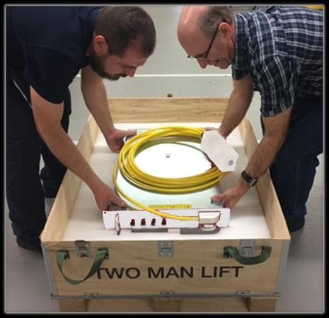
6.2 Unpacking and Handling
CAUTION: This PRISM Fiber Laser is heavy and so precautions
must be taken when lifting and moving.
Failure to do so may cause serious injury.
This Laser is heavy. Two people are required to unpack it. To avoid the risk of personal injury
or damage to the Laser when lifting or moving, lift with two people and use a trolley or similar
mechanical assistance when moving over distance.
Trumpf Laser UK Ltd. SM-S01076 Revision A Jan 2021 30
Commercial in Confidence 300W to 2.0kW Module Fiber Lasers Instructions for UsePrism Fiber Lasers
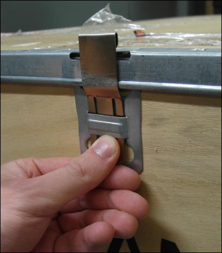
Figure 7 Removing Fastener
1. Undo all the fasteners which secure the lid (Figure 7).
2. Lift off the lid.
3. Remove the top layer of foam packaging. The Laser will appear as shown in Figure 8.
Figure 8 Crate without Lid and Top Layer of Foam Packaging
4. Remove the documentation.
5. Free the foam block containing the optical connector.
Trumpf Laser UK Ltd. SM-S01076 Revision A Jan 2021 31
Commercial in Confidence 300W to 2.0kW Module Fiber Lasers Instructions for UsePrism Fiber Lasers
6. Lift and hold the BDO away from the packaging (Figure 9) while a second person
removes the next layer of foam packaging.
Figure 9 Lift BDO to Enable the Next Layer of Packaging to be Removed
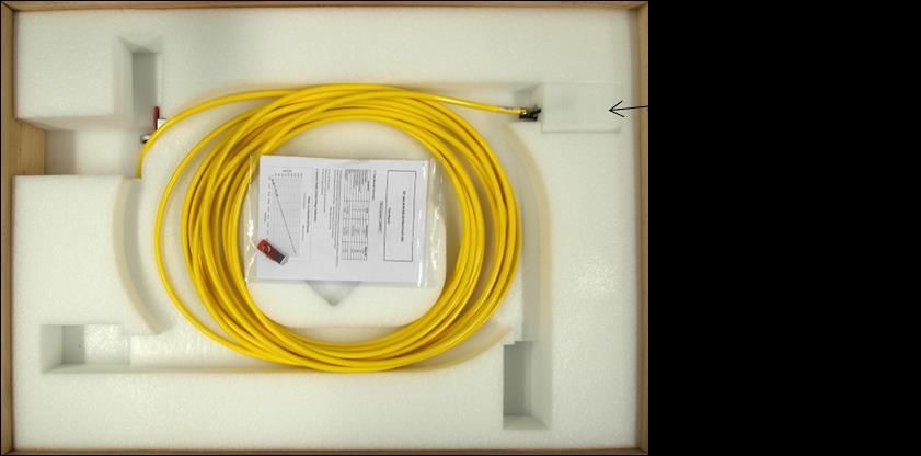
7. Replace the BDO (Figure 10).
Figure 10 BDO Replaced
8. Remove the foam inserts, if any (Figure 10).
Trumpf Laser UK Ltd. SM-S01076 Revision A Jan 2021 32
Commercial in Confidence 300W to 2.0kW Module Fiber Lasers Instructions for UsePrism Fiber Lasers
9. Lift the Laser from the crate (Figure 11). Do NOT use the BDO termination block on front
panel as a lifting handle. The small handles on the front panel are designed for sliding
the module in and out of the 19” rack system. Do not lift the whole weight of the module
using these handles
Figure 11 Lifting Laser from Crate
6.3 Unpacking the Beam Delivery Optic
Take care not to twist the conduit when uncoiling the BDO. Always unroll the conduit from the
free end, compensating for any twist that might occur. The conduit is very flexible and easily
bent when uncoiling. Ensure that is never bent to less than the minimum bend radius. Never
pull on the optical connector to untangle the conduit.
Particular care should be taken with regard to possible damage to the optical connector when
uncoiling the bean delivery optic as there is a tendency for the coil to spring apart, which may
cause the optical connector to collide with other objects. Do not drop the optical connector or
allow it to hit surfaces or other objects.
Finally remove the optical connector from the foam block by pushing the connector out of the
block. Use a finger inserted in the top of the block to push against the protective cap on the
optical connector.
Do not pull the block off as the protective cap may be inadvertently removed from the optical
connector exposing the window to contamination.
Trumpf Laser UK Ltd. SM-S01076 Revision A Jan 2021 33
Commercial in Confidence 300W to 2.0kW Module Fiber Lasers Instructions for UsePrism Fiber Lasers
7 Installation
7.1 Safety and Compliance During Installation
CAUTION: This PRISM Fiber Laser is heavy and so precautions
must be taken when lifting and moving.
Failure to do so may cause serious injury.
The Laser is heavy. To avoid the risk of personal injury or damage to the Laser when lifting or
moving, lift with two people and use a trolley or similar mechanical assistance when moving
over distance.
Before installation reference must be made to Section 3 regarding laser safety, electrical safety,
EMC and compliance. When installed, the laser and the additional equipment required to
operate it must not obstruct access to safety devices or impair their operation.
It is recommended that installation is done in the sequence of the following sections, with water
connections made and checked before electrical connections are made.
7.2 Location and Environment
This Laser is designed to be used in a 19” rack cabinet or other housing.
This Laser is designed for operation within the environment specified in Table 12. Operating the
Laser beyond the limits of the environmental specification may lead to accelerated component
ageing and performance degradation. As the Laser is water-cooled care must be taken to
ensure that it is always operated above the dew point so that internal condensation is avoided.
Refer to Figure 24 for a chart showing the relationship between relative humidity, ambient air
temperature and cooling water temperature for non-condensing operation.
This Laser must not be installed in a corrosive atmosphere.
This Laser must not be exposed to high levels of optical radiation, for instance laser radiation
from materials processing.
This Laser is sealed against dust and water ingress to IP52 to BS EN 60529:1992+A2:2013
with the exception of the electrical connectors which are rated IP50. The laser integrator must
ensure that when installed the Laser is not likely to be exposed to water, for instance from
coolant leaks.
At least 100mm clear space must be provided around the Laser to allow the BDO to be routed
correctly.
The optical connector shall be mounted in a protective housing which prevents human access
to laser radiation (including errant radiation) in excess of the AEL for class 1, for example a
housing meeting the requirements of EN 60825-4. The protective housing shall withstand
exposures under reasonably foreseeable single fault conditions without human intervention.
Trumpf Laser UK Ltd. SM-S01076 Revision A Jan 2021 34
Commercial in Confidence 300W to 2.0kW Module Fiber Lasers Instructions for UsePrism Fiber Lasers
7.3 Mounting
The total weight of the Laser is approximately 38kg for the long version and 26kg for the short
version. The front panel has the conventional 2U dimensions enabling the Laser to be fitted into
a standard 19” rack cabinet with its weight supported on runners. If mounted using the
mechanical mounting points specified in Section 11.5.1, all 8 (short modules) or all12 (long
modules) must be used to support its weight. The recommended torque for the M5 bolts is
3.5Nm. This value should be confirmed by the Laser Integrator. Alternatively, the Laser can be
placed on a clean, stable surface that will support its weight.
Ensure that the conduit carrying the delivery fiber is not kinked or snagged. Follow the guidance
given in and allow sufficient space for correct routing of the conduit. Failure to do so may result
in permanent damage to the delivery fiber.
7.4 PRISM Fiber Lasers with Bare Fiber Output
WARNING: PRISM Fiber Lasers with bare fiber output must be
spliced to an Trumpf Laser UK High Power Combiner.
Failure to do so will result in catastrophic damage to the Laser and
may result in exposure to hazardous laser radiation.
If the Laser is powered up without proper termination of the delivery fiber, the delivery fiber and
Laser may be catastrophically damaged. Laser Integrators must ensure that the delivery fiber
is properly terminated, for example by splicing to an Trumpf Laser UK HPC, prior to turning on
the Laser. Failure to do so may invalidate the warranty.
Further information on terminating the delivery fiber and HPCs can be provided by request from
Trumpf Laser UK.
Trumpf Laser UK Ltd. SM-S01076 Revision A Jan 2021 35
Commercial in Confidence 300W to 2.0kW Module Fiber Lasers Instructions for UsePrism Fiber Lasers
7.5 Cooling Water Connections
CAUTION: Ensure an approved overpressure safety device is
installed when connecting this Laser to an external chiller or factory
water supply. This should comply with ISO4126-1 (or equivalent)
and be rated to protect the Laser against a flow or differential water
pressure in excess of that specified.
CAUTION: If coolant is allowed to enter this Laser enclosure, do
not use the Laser and contact Trumpf Laser UK immediately.
Failure to do so may result in electrical shock and damage to the
Laser.
7.5.1 Base plate
The Laser must be operated with a source of chilled water as specified in Section 0. The base
plate has a cooling circuit. The cooling circuit is terminated with approximately 30mm copper
pipe protruding from the front panel. The cooling circuit must be connected with flow and return
as shown in Figure 12. Hoses must be routed, observing the specified bend radius, so that any
leaking cooling water will be kept away from the Laser, and provision must be made to shut
down the Laser and shut off the cooling water flow when a leak is detected.
For pipes and connectors see section 7.5.3
De-ionized water is not permitted in the cooling circuit to prevent corrosion.
Cooling water connections must be made and checked for leaks before making electrical
connections and powering up the Laser. To avoid potential water ingress the electrical
connectors should be capped while checking for leaks.
If an external coolant leak occurs and water comes into contact with any of the electrical
connectors, allow the Laser to dry completely before operating. If coolant is allowed to enter the
Laser enclosure, do not use the Laser and contact Trumpf Laser UK immediately.
Figure 12 Cooling Water Connections
Trumpf Laser UK Ltd. SM-S01076 Revision A Jan 2021 36
Commercial in Confidence 300W to 2.0kW Module Fiber Lasers Instructions for UsePrism Fiber Lasers
7.5.2 PIPA-Q Optical Connector
It is essential that the PIPA-Q optical connector is adequately cooled with a source of clean,
chilled water in accordance with the specifications listed in Section 11.3.2. Operating the PIPA-
Q optical connector without an adequate flow of cooling water may result in catastrophic
damage.
The inlet and outlet water connections are SMC MS-5HLH-6 type miniature hose elbows
suitable for 6mm LLDPE or polyurethane tubing.
7.5.3 Cooling Water Fittings
The Laser is not supplied with water fittings. Trumpf Laser UK recommends that the widely
available push-on John Guest ‘Speedfit’ water connections are used to connect the cooling
circuit to the chilled water supply. Ensure that the pipes are clean before adding the
connections and that the correct locking clips are used. John Guest part numbers are given in
Table 5.
For modules up to and including 1kW use 10mm fittings.
For modules 1.5kW and above use 12mm fittings.
Table 5 Water Tubing and Fittings
Module type Diameter John Guest Trumpf Laser UK
Part Number Part Number
= 1.5kW 12mm equal elbow PM0312E PT-M07538
When using ‘Speedfit’ the water connection should be made as follows:
• Cut the tube square and remove burrs and sharp edges. Ensure the outside diameter is
free of score marks. Push the tube into the fitting, to the tube stop.
• Push the locking clip onto the fitting behind the collet.
• Pull on the tube to check it is secure. Test the system before use.
Trumpf Laser UK Ltd. SM-S01076 Revision A Jan 2021 37
Commercial in Confidence 300W to 2.0kW Module Fiber Lasers Instructions for UseYou can also read