Product Name Quick Reference Guide - Part No. 875-0315-000 Rev A1 - Hemisphere GNSS
←
→
Page content transcription
If your browser does not render page correctly, please read the page content below
A320/A321 Smart
     Product    Antenna
             Name
   QuickUser GuideGuide
        Reference
   Part No. 875-0315-000
             Part No. Rev A1
This device complies with part 15 of the FCC Rules. Operation is subject to the following two
conditions:
(1) This device may not cause harmful interference, and
(2) this device must accept any interference received, including interference that may cause
undesired operation.

Copyright Notice
Hemisphere GPS Precision GPS Applications
Copyright © Hemisphere GPS (2012). All rights reserved.
No part of this manual may be reproduced, transmitted, transcribed, stored in a retrieval system or
translated into any language or computer language, in any form or by any means, electronic,
mechanical, magnetic, optical, chemical, manual or otherwise, without the prior written
permission of Hemisphere GPS.

Trademarks
Hemisphere GPS®, the Hemisphere GPS logo, A100TM, A20TM, A21TM, A220TM, A221TM, A30TM,
A31TM, A320TM, A321TM, A42TM, A52TM, AC110TM, AerialACETM, AirStarTM, AirTracTM, AutoMateTM,
BantamTM, BaseLineHDTM, BaseLineXTM, BEELINE®, COASTTM, Contour LockTM, Crescent®,
Earthworks®, EclipseTM, e-Dif®, eDrive®, eDriveTCTM, eDriveVSiTM, eDriveXTM, FliteTracTM, G100TM,
G4TM, GateMateTM, GPSteerTM, H102TM, H320TM, HQTM, IntelliFlow®, IntelliGateTM, IntelliStarTM,
IntelliTracTM, Just Let GoTM, L-DifTM, LiteStar IITM, LV101TM, LX-1TM, LX-2TM, M3TM, MapStar®,
MBX-4TM, miniEclipseTM, OutbackTM, Outback 360TM, Outback Guidance CenterTM, Outback
Guidance®, Outback HitchTM, Outback STM, Outback S2TM, Outback S3TM, Outback S-LiteTM, Outback
StsTM, Outback Steering GuideTM, PocketMAX PCTM, PocketMAXTM, PocketMax3TM, R100TM, R131TM,
R220TM, R320TM, S320TM, Satloc®, the Satloc logo, SBX-4TM, V101TM, V102TM, V103TM, V111TM, V113TM,
VS101TM, VS111TM, VS131TM, VectorTM, X200TM, X300TM, XF1TM, XF100TM, XF101TM, and XF102TM are
proprietary trademarks of Hemisphere GPS. Other trademarks are the properties of their
respective owners.

Patents
The Outback STM and S-LiteTM automated navigation and steering guide systems are covered by
U.S. Patents No. 6,539,303 and No. 6,711,501. The Outback HitchTM automated hitch control system
is covered by U.S. Patent No. 6,631,916. The Outback eDriveTCTM GPS assisted steering system is
covered by U.S. Patent No. 7,142,956. Hemisphere GPS products may be covered by one or more
of the following U.S. Patents:
 6,111,549           6,397,147            6,469,663          6,501,346           6,539,303
 6,549,091           6,631,916            6,711,501          6,744,404           6,865,465
 6,876,920           7,142,956            7,162,348          7,277,792           7,292,185
 7,292,186           7,373,231            7,400,956          7,400,294           7,388,539
 7,429,952           7,437,230            7,460,942
Other U.S. and foreign patents pending.
Notice to Customers
Contact your local dealer for technical assistance. To find the authorized dealer near you:
Hemisphere GPS
4110 9th Street S.E.
Calgary, Alberta, Canada T2G 3C4
Phone: 403-259-3311
Fax: 403-259-8866
precision@hemispheregps.com
www.hemispheregps.com

Technical Support
If you need to contact Hemisphere GPS Technical Support:
8444 N 90th St, Suite 130
Scottsdale, AZ 85258 USA
Phone: (480) 348-9919
Fax: (480) 348-6370
techsupport@hemispheregps.com

Documentation Feedback
Hemisphere GPS is committed to the quality and continuous improvement of our products and
services. We urge you to provide Hemisphere GPS with any feedback regarding this guide by
writing to the following email address: DocFeedback@hemispheregps.com.
Contents

Chapter 1             Introducing the A320/321 . . . . . . . . . . . . . . . . . . . 1
                      A320/321 Overview . . . . . . . . . . . . . . . . . . . . . . . . . . . . . . . . . . . . . . 2
                      Key Features . . . . . . . . . . . . . . . . . . . . . . . . . . . . . . . . . . . . . . . . . . . . 3
                      What’s Included . . . . . . . . . . . . . . . . . . . . . . . . . . . . . . . . . . . . . . . . . 3
                      Ports and Connections . . . . . . . . . . . . . . . . . . . . . . . . . . . . . . . . . . . . 4
                             A320 Ports and Connections . . . . . . . . . . . . . . . . . . . . . . . . . . . 4
                             A321 Ports and Connections . . . . . . . . . . . . . . . . . . . . . . . . . . . 5
                      Display Panel . . . . . . . . . . . . . . . . . . . . . . . . . . . . . . . . . . . . . . . . . . . 6
                             A320 Display Panel . . . . . . . . . . . . . . . . . . . . . . . . . . . . . . . . . . 6
                             A321 Display Panel . . . . . . . . . . . . . . . . . . . . . . . . . . . . . . . . . . 6
                             LED Indicators . . . . . . . . . . . . . . . . . . . . . . . . . . . . . . . . . . . . . . 7
                      Radio Options . . . . . . . . . . . . . . . . . . . . . . . . . . . . . . . . . . . . . . . . . . . 7
                      Obtaining Product Updates . . . . . . . . . . . . . . . . . . . . . . . . . . . . . . . . 7

Chapter 2             Installing the A320/321 . . . . . . . . . . . . . . . . . . . . . 9
                      Installing the A320 . . . . . . . . . . . . . . . . . . . . . . . . . . . . . . . . . . . . . . 10
                             Selecting the Proper Antenna Location . . . . . . . . . . . . . . . . . 10
                             Routing and Securing the Cables . . . . . . . . . . . . . . . . . . . . . . 11
                             Mounting the A320 . . . . . . . . . . . . . . . . . . . . . . . . . . . . . . . . . 11
                             Connecting the A320 to External Devices . . . . . . . . . . . . . . . 11
                             Powering the A320 . . . . . . . . . . . . . . . . . . . . . . . . . . . . . . . . . . 11
                      Installing the A321 . . . . . . . . . . . . . . . . . . . . . . . . . . . . . . . . . . . . . . 12
                             Mounting the A321 . . . . . . . . . . . . . . . . . . . . . . . . . . . . . . . . . 12
                             Powering the A321 . . . . . . . . . . . . . . . . . . . . . . . . . . . . . . . . . . 13

Chapter 3             Operating the A320/321 . . . . . . . . . . . . . . . . . . . . 15
                      Using the Menus . . . . . . . . . . . . . . . . . . . . . . . . . . . . . . . . . . . . . . . 16
                             Obtaining and Setting Up Remote Control Software . . . . . . 16
                             Comparing Remote Control Software to the A321 Physical Dis-
                             play Panel . . . . . . . . . . . . . . . . . . . . . . . . . . . . . . . . . . . . . . . . . 16
                             GNSS Signal Level Display . . . . . . . . . . . . . . . . . . . . . . . . . . . 17
                             Navigating the Menus and Selecting Menu Items . . . . . . . . 18
                             Menu and Menu Item Selection in This User Guide . . . . . . . 19
                             Top Menu Overview . . . . . . . . . . . . . . . . . . . . . . . . . . . . . . . . 20
                      A320/321 Radio Configuration Overview . . . . . . . . . . . . . . . . . . . . 21
                      Configuring Your A320/321 400 MHz Microhard Radio . . . . . . . . 21
                             Setting the Radio Mode of Operation . . . . . . . . . . . . . . . . . . 21
                             Setting the Frequency . . . . . . . . . . . . . . . . . . . . . . . . . . . . . . . 23
                             Setting the Power . . . . . . . . . . . . . . . . . . . . . . . . . . . . . . . . . . 25

A320/321 User Guide                                      iii                               PN 875-0315-000 Rev A1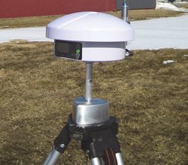
Contents

                             Encrypting RTK Data Using the Microhard Radio Static Mask
                             27
                             Typical Distance Performance . . . . . . . . . . . . . . . . . . . . . . . . 29
                      Configuring Your A320/321 900 MHz Microhard Radio . . . . . . . . 31
                             Setting the Radio Mode of Operation . . . . . . . . . . . . . . . . . . 31
                             Setting the Channel . . . . . . . . . . . . . . . . . . . . . . . . . . . . . . . . . 33
                             Setting the Power . . . . . . . . . . . . . . . . . . . . . . . . . . . . . . . . . . 34
                             Checking VSWR . . . . . . . . . . . . . . . . . . . . . . . . . . . . . . . . . . . . 36
                             Checking RSSI . . . . . . . . . . . . . . . . . . . . . . . . . . . . . . . . . . . . . 36
                      Operating the A320 . . . . . . . . . . . . . . . . . . . . . . . . . . . . . . . . . . . . . 37
                      Operating the A321 . . . . . . . . . . . . . . . . . . . . . . . . . . . . . . . . . . . . . 37
                             Begin Using the A321 . . . . . . . . . . . . . . . . . . . . . . . . . . . . . . . 38
                             Base Station Operating Modes . . . . . . . . . . . . . . . . . . . . . . . . 40
                             Setting the A321 as a Fixed Base Station . . . . . . . . . . . . . . . 40
                             Setting the A321 as a Portable Base Station . . . . . . . . . . . . . 44
                             Setting an Alternate Reference Point . . . . . . . . . . . . . . . . . . . 44
                             Managing Configurations . . . . . . . . . . . . . . . . . . . . . . . . . . . . 45
                             USB Data Logging . . . . . . . . . . . . . . . . . . . . . . . . . . . . . . . . . . 46

Appendix A            Technical Specifications . . . . . . . . . . . . . . . . . . . 47

Appendix B            Menu Map . . . . . . . . . . . . . . . . . . . . . . . . . . . . . . . 51
                      Top Menu . . . . . . . . . . . . . . . . . . . . . . . . . . . . . . . . . . . . . . . . . . . . . 52
                      GPS/GNSS Menu . . . . . . . . . . . . . . . . . . . . . . . . . . . . . . . . . . . . . . . 53
                      SBAS Menu . . . . . . . . . . . . . . . . . . . . . . . . . . . . . . . . . . . . . . . . . . . 54
                      Base Station Menu . . . . . . . . . . . . . . . . . . . . . . . . . . . . . . . . . . . . . . 55
                      Config Wizard Menu . . . . . . . . . . . . . . . . . . . . . . . . . . . . . . . . . . . . 56
                      System Setup Menu . . . . . . . . . . . . . . . . . . . . . . . . . . . . . . . . . . . . 57
                      Data Logging Menu . . . . . . . . . . . . . . . . . . . . . . . . . . . . . . . . . . . . . 58

Appendix C            Using Remote Control . . . . . . . . . . . . . . . . . . . . . 59
                      Starting Remote Control . . . . . . . . . . . . . . . . . . . . . . . . . . . . . . . . . 60
                      Radio Tab . . . . . . . . . . . . . . . . . . . . . . . . . . . . . . . . . . . . . . . . . . . . . 60
                             Microhard Radio Installed . . . . . . . . . . . . . . . . . . . . . . . . . . . . 60
                             Advanced Radio Control . . . . . . . . . . . . . . . . . . . . . . . . . . . . . 61
                      Base Station Tab . . . . . . . . . . . . . . . . . . . . . . . . . . . . . . . . . . . . . . . 62

Index . . . . . . . . . . . . . . . . . . . . . . . . . . . . . . . . . . . . . . . . . . . . . . . 65

End User License Agreement . . . . . . . . . . . . . . . . . . . . . . . . . . . . 69

Warranty Notice . . . . . . . . . . . . . . . . . . . . . . . . . . . . . . . . . . . . . . 72

A320/321 User Guide                                      iv                                PN 875-0315-000 Rev A1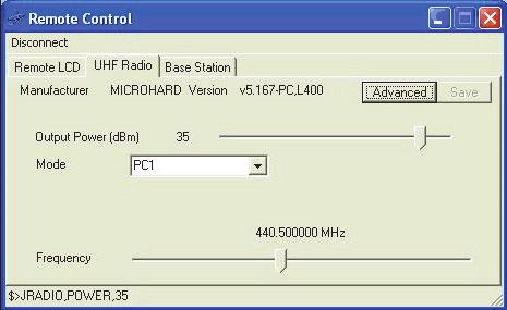
Chapter 1: Introducing the A320/321
                                             A320/321 Overview
                                                     Key Features
                                                 What’s Included
                                           Ports and Connections
                                                    Display Panel
                                                   Radio Options

A320/321 User Guide               1           PN 875-0315-000 Rev A1
Chapter 1: Introducing the A320/321

A320/321 Overview
The A320/321 smart antennas offer fast, portable, professional-level accuracy in a
rugged, all-in-one enclosure. The A320/321 comprises the following models:
     •    A320™ Smart Antenna
     •    A321™ Smart Antenna

Note: When referring to both the A320 and the A321 this manual uses the term A320/
321. When referring to one antenna or the other this manual uses the name of the
specific antenna (A320 or A321).

                    A320                                         A321

                        Figure 1-1: A320/321 smart antennas

The A320/321 smart antennas offer versatile, portable solutions with centimeter-level
accuracy powered by Hemisphere GPS’ Eclipse™ II multifrequency GNSS receiver
technology.
With the Eclipse II GNSS OEM module, RTK performance is scalable. Utilize the same
centimeter-level accuracy in either L1-only mode, or employ the full performance of
fast RTK over long distances with L1/L2 GNSS signals. Hemisphere GPS’ exclusive
SureTrack™ technology ensures your RTK rover is making use of every satellite it is
tracking, even satellites not tracked at the base. Benefit from fewer RTK dropouts in
congested environments, faster reacquisitions, and more robust solutions due to
better cycle slip detection. SureTrack also removes concerns with mixing GNSS data
from various manufacturers. Even if your base is only L1/L2 GPS, SureTrack with
GLONASS at your rover delivers complete GNSS performance.
The durable enclosures house the receivers, antennas, and optional radio modems, all
in one package. They can be powered through various sources, making the A320/321
ideal for a variety of applications, where:
     •    A320 is designed to be mounted on a variety of roving machines and
          vehicles for kinematic positioning and navigation applications
     •    A321 can be used as a portable base station mounted on a tripod or riser,
          includes a full graphic display with menu selection keys, and can log data to
          a standard USB flash drive

A320/321 User Guide                        2                     PN 875-0315-000 Rev A1
Chapter 1: Introducing the A320/321

Key Features
Key features of the A320/321 include:
    •    Centimeter-level accuracy using Eclipse II technology in a rugged, all-in-one
         enclosure
    •    Improved GNSS performance, particularly with RTK and GLONASS
         applications through the implementation of SureTrack technology
    •    Eclipse II RTK engine capable of converging at long range baselines up to
         50 km (radio link dependent)

         Note: The 400 MHz radio link limits RTK distances. See “Typical Distance
         Performance” on page 29 for more information.

    •    High-precision positioning in RTK, L-band, and SBAS/DGPS modes
    •    Supports NMEA 2000®, NMEA 0183, binary, and USB for communication
         with external devices
    •    Compatible with RTK reference networks through RTCM v3 or CMR/CMR+
         corrections
    •    SBAS satellite ranging technology increases the number of satellites in view
         for greater speed and reliability
    •    SureTrack technology for fewer RTK dropouts in congested environments,
         faster re-acquisitions, better cycle slip detection, and the assurance that
         even if the base supports only GPS the rover will process GLONASS signals
         to deliver complete GNSS performance
    •    Internal radio bay supports Microhard radios
The A320/321 supports a variety of communication protocols for communicating with
navigation systems, data loggers, CAN systems and other devices. See Appendix A,
“Technical Specifications” for a list of communication protocols supported by the
A320/321 (Table A-3 on page 48) as well other technical specifications.

What’s Included
The parts included in your A320 or A321 kit depend on the configuration you
purchased. All kits include the following:
    •    A320 or A321 antenna
    •    Power and data cables
    •    Mounting hardware
    •    User Guide and Quick Reference Guide
Contact your dealer for questions about the parts included in your kit.

A320/321 User Guide                        3                       PN 875-0315-000 Rev A1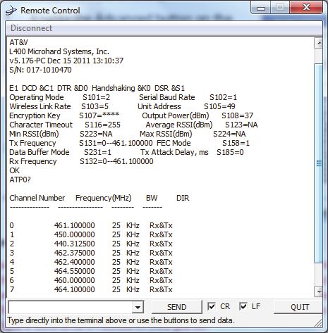
Chapter 1: Introducing the A320/321

Ports and Connections
A320 Ports and Connections
Figure 1-2 shows the ports and connections for the A320 and Table 1-1 provides
additional information about each port/connection.

        Antenna port

               Power/data port

                        Figure 1-2: A320 ports and connections

Table 1-1: A320 ports and connections

 Port                    What to connect

 Radio antenna port      External antenna (radio connector)
 Power/data port         External power/data cable; allows you to supply power to the A320
 (circular connector)    as well as communicate with external devices via CAN (NMEA
                         2000), NMEA 0183 serial, and binary

A320/321 User Guide                           4                     PN 875-0315-000 Rev A1
Chapter 1: Introducing the A320/321

A321 Ports and Connections
Figure 1-3 shows the ports and connections for the A321 and Table 1-2 provides
additional information about each port/connection.

        Antenna port

                                                                             Serial ports
  Mounting hole
  (if using pole
  or tripod)

                                                                             USB flash drive
    USB cable port                                                           (data storage)
    (data transfer)

               Power port

                       Figure 1-3: A321 ports and connections

Table 1-2: A321 ports and connections

 Port                   What to connect

 Radio antenna port     External antenna (radio connector)
 Serial port            External serial devices
                        DB9 connection that allows you to update software or set advanced
                        configuration options. Both DB9 serial ports can be used at the
                        same time; for example, you can use Port A to receive RTK
                        corrections while using Port B to output NMEA messages.
                        For information on outputting NMEA messages refer to the
                        Hemisphere GPS Technical Reference (go to
                        www.hemispheregps.com/support and click the GPS Reference
                        icon).
 USB cable port         USB data cable
                        Advanced service and applications, supporting a direct connection
                        to a PC via USB cable.
 USB data port          USB flash drive (port is labeled ‘USB STICK’)
 Power port             External power cable
 Mounting hole          Pole or tripod mount

A320/321 User Guide                            5                        PN 875-0315-000 Rev A1
Chapter 1: Introducing the A320/321
Display Panel
This section describes the display panel on the A320 and the A321 and provides
information on the LED indicators that are common to both the A320 and A321.
A320 Display Panel
The A320 display panel consists of LED indicators for power, GPS, and DGPS.
Power indicator
GPS indicator
DGPS indicator
Figure 1-4: A320 display panel
Refer to the following sections for more information on using the control panel:
• “LED Indicators” on page 7
• “Connecting the A320 to External Devices” on page 11
• “Operating the A320” on page 37
A321 Display Panel
The A321 display panel allows you to select menu options and view power and GPS
status.
Power indicator
Up Arrow button
(scroll up through items)
Enter button
(select an item)
Down Arrow button
(scroll down through items)
DGPS indicator
Menu GPS indicator
Figure 1-5: A321 display panel
Refer to the following sections for more information on using the control panel:
• “LED Indicators” on page 7
• “Powering the A321” on page 13
• “Operating the A321” on page 37
A320/321 User Guide 6 PN 875-0315-000 Rev A1Chapter 1: Introducing the A320/321
LED Indicators
The A320/321 uses LEDs to indicate power, GPS lock, and DGPS position. There is a
corresponding icon to the right of each LED. Table 1-3 describes each LED indicator.
Table 1-3: LED display
LED
LED Function Description
Color
Power Red Power on
GPS Yellow GPS lock
• Solid LED indicates GPS lock
• Blinking LED indicates acquiring data
DGPS Green DGPS position
• Solid LED indicates differential position
achieved
• Blinking LED indicates broadcast (A321)
or reception (A320) of differential
corrections
Radio Options
The following radio configurations are available for the A320/321.
• No radio kit (basic version)
• Microhard radio kit
To purchase an optional radio, contact your dealer.
For information on configuring a Microhard radio see the following:
• “Configuring Your A320/321 400 MHz Microhard Radio” on page 21
• “Configuring Your A320/321 900 MHz Microhard Radio” on page 31
Obtaining Product Updates
Contact your dealer or visit the Hemisphere GPS website at www.hemispheregps.com
to obtain product updates for A320/321 firmware, software (such as Remote Control),
and GPS applications.
A320/321 User Guide 7 PN 875-0315-000 Rev A1Chapter 2: Installing the A320/321
Installing the A320
Installing the A321
A320/321 User Guide 9 PN 875-0315-000 Rev A1Chapter 2: Installing the A320/321
This chapter provides instructions for installing your A320/321. It includes the
following sections:
A320 A321
• Selecting the proper antenna location • Mounting the A321
• Routing and securing the cables • Powering the A321
• Mounting the A320 Note: The A321 is pre-configured for use as
• Connecting the A320 to external a base station in an RTK system. The
devices provided kit includes everything you need
to set up and begin using your base station.
• Powering the A320
Installing the A320
This section covers the following topics:
• Selecting the proper antenna location (below)
• Routing and securing the cables (below)
• Mounting the A320
• Connecting the A320 to external devices
• Powering the A320
Selecting the Proper Antenna Location
Proper antenna placement is critical to positioning accuracy.
To select the proper antenna location:
1. Place the antenna with an
unobstructed view of the
sky.
Note: An obstructed view
of the sky may impair
system performance. The
GPS engine computes a
position based on
measurements from each
satellite to the internal GPS Ideal antenna placement
on vehicle
receiver.
2. Mount the antenna on, or as close as possible to, the center of your point of
measurement.
3. Position the antenna as high as possible.
A320/321 User Guide 10 PN 875-0315-000 Rev A1Chapter 2: Installing the A320/321
Routing and Securing the Cables
Consider the following when routing cables:
• Do not run cables in areas of excessive heat
• Do not expose cables to corrosive chemicals
• Do not crimp or excessively bend cables
• Do not place tension on cables
• Coil up excess cable in the cab of the vehicle
• Secure along the cable route using plastic tie wraps as necessary
• Do not run cables near high voltage or strong RF noise and transmitter
sources
Improperly installed cables near machinery may cause injury or death.
Mounting the A320
The A320 features a built-in magnetic mount. Simply place the A320 on your vehicle in
the appropriate location. See “Selecting the Proper Antenna Location” on page 10.
Connecting the A320 to External Devices
The A320 can communicate with a variety of external data loggers, rate controllers,
yield monitors, or other devices. The external device must be connected through the
DB9 serial port of the A320 power cable.
Note: Contact your dealer to obtain a suitable adapter cable.
Powering the A320
To power the A320:
1. Turn on the power switch on the A320 power cable.
2. Check the functionality of the A320 by monitoring the Power LED.
Do not apply a voltage higher than 36 VDC. This will damage the
receiver and void the warranty.
A320/321 User Guide 11 PN 875-0315-000 Rev A1Chapter 2: Installing the A320/321
Installing the A321
This section covers the following topics:
• Mounting the A321
• Powering the A321
Mounting the A321
You can mount the A321 in either of the following ways,
depending on the kit you purchased:
• Fixed base station using the included mounting
bracket
• Portable base station using the included tripod
stem and adapter
A321 with fixed/pole
mounting hole
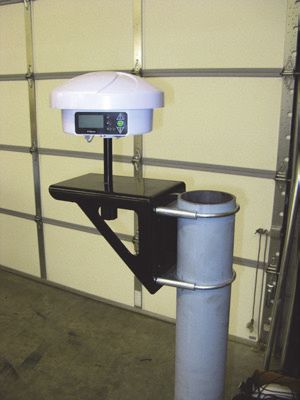
Fixed Base Station Mounting
Fixed base station kits for the A321 include a
right angle mounting bracket. After you
mount the bracket you screw the A321 onto
the bracket.
To mount the A321 as a fixed base station:
1. Attach the mounting bracket to a
secure location using the supplied
hardware.
2. Thread the center hole of the A321
onto the bolt that is permanently
fixed to the mounting bracket.
A320/321 User Guide 12 PN 875-0315-000 Rev A1Chapter 2: Installing the A320/321
Portable Base Station Mounting
Mount the A321 to the tripod using the provided tripod adapter.
To mount the A321 as a portable base station:
1. Thread the provided tripod stem
onto the tripod adapter.
Tripod
2. Mount the tripod adapter unit onto stem
the tripod, leaving the adapter
loose on the tripod. Tripod
adapter
Tripod
3. Thread the center hole of the A321 onto
the tripod stem.
4. Position the A321 in the desired
orientation and tighten the adapter onto
the tripod.
Powering the A321
Depending on the parts included in your A321 kit you can the power the A321 via
either of the following:
• 110/220 V AC power cable
• Power cable (terminated with battery clips) to connect to a 12 V battery*
*You can use a 12 V car battery or, if you purchased a portable base station
kit, you can use the included 12 V battery
The A321 is automatically “on” upon connecting a power source.
Note: The following procedure describes how to connect the A321 to a 12 V car
battery using the power cable (terminated with battery clips) included in some A321
kits. If your kit includes the 110/220 V AC power cable connect the power cable to a
suitable power source in step 2.
A320/321 User Guide 13 PN 875-0315-000 Rev A1Chapter 2: Installing the A320/321
To connect a power source to the A321:
1. Connect the provided power cable to the A321’s power port. See Figure 1-3
on page 5 for the location of the power port.
2. Attach the positive and
negative leads at the
opposite end of the
power cable to the
positive and negative
terminals of a car battery.
Note: If you purchased
the portable base station
kit, the connection to the Power cable connected
12 V battery is the same to battery
as shown at right.
A321 connected
to battery
3. Check the Power LED on the A321—a red LED
Power LED is on (red)
indicates a successful connection and the
A321 has power. See “LED Indicators” on
page 7 for more information on the display
panel LEDs.
A320/321 User Guide 14 PN 875-0315-000 Rev A1Chapter 3: Operating the A320/321
Using the Menus
A320/321 Radio Configuration Overview
Configuring Your A320/321 400 MHz Microhard Radio
Configuring Your A320/321 900 MHz Microhard Radio
Operating the A320
Operating the A321
A320/321 User Guide 15 PN 875-0315-000 Rev A1Chapter 3: Operating the A320/321
This chapter provides an overview of using the menu system as well as basic
configuration and operation instructions for your A320/321:
• For using your A320 see “Operating the A320” on page 37
• For using your A321 see “Operating the A321” on page 37
Using the Menus
The A321 includes a menu system you access from the display panel; see “A321
Display Panel” on page 6 for a brief overview. Although the A320 does not include a
menu system accessible from its display panel, you can use Hemisphere GPS’ Remote
Control software to perform many of the same tasks that you can with the A321’s
menu system. Even though the A321 has a physical display panel, you can use
Remote Control with the A321 as well.
Note: The following sections refer to the A321 physical display panel or the A320 or
A321 using Remote Control software.
Obtaining and Setting Up Remote Control Software
Remote Control is available from the Hemisphere GPS website.
1. Open a web browser and go to www.hemispheregps.com.
2. Navigate to Support > Precision Product Support > Antennas >
Software.
3. Click the Remote Control link and save the download to your PC.
4. Install the software.
To use Remote Control software you must connect your A320/321 to your PC (on
which Remote Control is installed) using a serial cable. Just power on your receiver
and start Remote Control and you can begin using the software.
Comparing Remote Control Software to the A321 Physical
Display Panel
Figure 3-1 shows the physical display panel of the A321 alongside the Remote Control
software display panel.
A320/321 User Guide 16 PN 875-0315-000 Rev A1Chapter 3: Operating the A320/321
Note: There is a slight delay (a second or so) when using Remote Control (the screen
may not refresh immediately).
A321 display panel Remote Control display panel
Figure 3-1: A321 display panel vs. Remote Control display panel
GNSS Signal Level Display
Channel
bars
Figure 3-2: A321 menu
As shown in Figure 3-2 the channel bars above the menu visually display each
channel's tracking status (one bar section for each channel) as follows:
• When tracking L1 GPS only, each bar represents L1
GPS.
• When tracking L1/L2 GPS, each bar is two separate
bars (starting from the left, first bar for L1 GPS,
second bar for L2 GPS)
• When tracking L1/L2 GPS and GLONASS, each bar is
four separate bars (starting from the left, first bar for
L1 GPS, second bar for L2 GPS, third bar for L1
GLONASS, fourth bar for L2 GLONASS)
Note: If you have a GLONASS subscription, the first menu item on the Top menu is
GNSS. If you do not have a GLONASS subscription, the first menu item is GPS.
A320/321 User Guide 17 PN 875-0315-000 Rev A1Chapter 3: Operating the A320/321
Navigating the Menus and Selecting Menu Items
Whether you are using the physical display on the A321 or you have an A320 or A321
connected to a PC and are running Remote Control, on startup the Top menu appears.
Figure 3-3: Top menu
The A320/321 front panel contains three soft buttons: Up Arrow, Enter, and Down
Arrow (see Figure 3-4).
Up Arrow button
(scroll up through items)
Enter button
(select an item)
Down Arrow button
(scroll down through items)
Figure 3-4: Menu buttons
In addition to selecting items you can return to previous menu levels using the
following menus items:
• Select Back to return to the previous menu level
• Select Top Menu to return to the Top menu
A320/321 User Guide 18 PN 875-0315-000 Rev A1Chapter 3: Operating the A320/321
Table 3-1 describes the indicators that appear to the right of specific menu items.
Table 3-1: Menu item indicators
Indicator Purpose Example
Go to the indicated submenu 1. On the Top menu press the Down
This indicator also appears Arrow button to highlight System
to the right of the “Back” and Setup. The Display indicator appears
“Top Menu” menu items. to the right of System Setup.
• Pressing Enter when 2. Press Enter to display the System
Display “Back” is selected Setup menu.
indicator returns you to the 3. Press the Down Arrow button again
previous menu. to highlight the Display Format
• Pressing Enter when option and then press Enter. The
“Top Menu” is items on the Display Format menu
selected returns you appear and the Select indicator
to the Top menu. appears to the right of Disp Update
(the first item on the Display Format
Scrolls within a menu to menu).
highlight an option to select. 4. Press Enter on the Disp Update item.
The Display indicator changes to the
Select indicator.
5. Press the Up Arrow or Down
Select Arrow button to scroll through the
indicator available options (such as 1Hz and
5Hz).
6. Press Enter on the highlighted
option to select it. That option is now
the setting for the menu item and the
Select indicator changes back to the
Display indicator.
Menu and Menu Item Selection in This User Guide
For many instructions in this User Guide the following example illustrates the
nomenclature used for navigating the menus.
“On the Top menu select Data Logging > Config” is the equivalent to saying “On
the Top menu select Data Logging and press Enter. Then select Config and press
Enter.”
When making selections for a menu item, such as selecting Yes or No for Auto-Name
(Data Logging > Config menu), the instructions will indicate to select the menu item
and press Enter to allow you to then select an option for that menu item and then
press Enter again to select that option.
Entering Alphanumeric Characters
Use the Up Arrow and Down Arrow buttons to enter alphanumeric characters (for
example, when entering a job name or a subscription code).
To enter alphanumeric characters:
A320/321 User Guide 19 PN 875-0315-000 Rev A1Chapter 3: Operating the A320/321
1. At the prompt, press the Down
Arrow button to scroll to the
desired character. Down
Arrow
The character appears on a black
button
background when the prompt is
active.
2. Press Enter to select the
character. The prompt moves to
Enter
the next character. button
3. Press Enter when done.
Top Menu Overview
Refer to Appendix B, “Menu Map” for a complete menu map for the following options
on the Top menu:
• GPS/GNSS
• Differential corrections (menu item will be the selected differential source,
such as SBAS or Autonomous)
• Base Station (A321 only)
• Config (configuration) Wizard
• System Setup
• Data Logging
A320/321 User Guide 20 PN 875-0315-000 Rev A1Chapter 3: Operating the A320/321
A320/321 Radio Configuration Overview
If your A320/321 antenna has an optional radio use the information in this section to
configure the A320/321 to set the following:
• Radio mode of operation
• Channel/frequency
• Power
Note: The radio mode and channel/frequency of the A320 rover must match that of
the A321 base station for the A320 rover to successfully receive the broadcasted RTK
messages.
Some configuration steps will differ slightly depending on the type of radio you have
installed in your A320/321.
• If you have a Microhard 400 MHz radio installed go to “Configuring Your
A320/321 400 MHz Microhard Radio” below.
• If you have a Microhard 900 MHz radio installed go to “Configuring Your
A320/321 900 MHz Microhard Radio” on page 31.
Additionally, for the 400 MHz radio you can encrypt RTK data using the Microhard
radio static mask (see page 27).
Configuring Your A320/321 400 MHz
Microhard Radio
Setting the Radio Mode of Operation
The radio mode refers to a Hemisphere GPS-proprietary mode or a number of
industry-standard compatible modes—see Table 3-2 on page 23 for more information
on supported radio modes.
Note: The following steps show how to use Remote Control software to set the mode.
Follow the same steps if using the actual menu on the A321 to set its mode.
A320/321 User Guide 21 PN 875-0315-000 Rev A1Chapter 3: Operating the A320/321
Complete the following steps to set the radio mode:
Step Base Station Screen Item Rover Screen Item
Base Station
1. On the Top menu scroll
to and select Base
Station.
Rover
1. On the Top menu scroll
to and select RTK.
2. Scroll to (if necessary)
and select Radio.
3. Scroll to and select
Mode.
4. Use the Up Arrow and
Down Arrow buttons
to display the desired
mode and press Enter
to select the mode.
A320/321 User Guide 22 PN 875-0315-000 Rev A1Chapter 3: Operating the A320/321
Table 3-2 describes the available radio modes. Pac Crest provides a configuration tool
that allows you to view the parameters in the Description column; therefore, select the
mode you need based on these parameters (PC1 and PC3 differ only by the FEC
parameter: ON or OFF).
Note: Hemisphere GPS recommends PC1 for most applications. You should only use
PC3 if your are trying to maintain compatibility with an existing Pac Crest network.
Table 3-2: 400 MHz Microhard radio modes
Mode Description Comment
PC1 9600 bps link rate, Compatible with Pac Crest and Satel. This is the most
GMSK, FEC ON, common mode of operation and generally provides the
Scrambling ON best distance performance. Throughput is limited to
approximately 5600 bits/sec.
PC2 Future mode, currently not supported
PC3 9600 bps link rate, Compatible with Pac Crest. This mode provides slightly
GMSK, FEC OFF, inferior distance performance compared to PC1, but
Scrambling ON provides better throughput of approximately 8300 bits/
sec.
PC4 Future mode, currently not supported
HGPS 16000 bps link This mode is similar to PC3, but provides better
rate, FEC OFF, throughput of approximately 14000 bit/sec, while still
Scrambling ON maintaining excellent sensitivity. This mode also
allows setup of network repeaters and
retransmissions.
Setting the Frequency
You must obtain a valid radio license for your jurisdiction before using
the A320/321 with 400 MHz radio. Only set the radio to the frequency and power you
are licensed to use at your location.
Each A321 base station and A320 rover in a network must be configured to operate on
the same frequency.
You can set the frequency to any value between 410 MHz and 480 MHz. The frequency
must be a multiple of 0.0125 MHz (12.5 kHz). If you enter an invalid frequency, it will be
rejected with an “INVALID” error.
Note: The following steps show how to use Remote Control software to set the
frequency. Follow the same steps if using the actual menu on the A321 to set its
frequency.
A320/321 User Guide 23 PN 875-0315-000 Rev A1Chapter 3: Operating the A320/321
Complete the following steps to set the frequency:
Step Base Station Screen Item Rover Screen Item
Base Station
1. On the Top menu scroll
to and select Base
Station.
Rover
1. On the Top menu scroll
to and select RTK.
2. Scroll to (if necessary)
and select Radio.
3. Scroll to and select
Freq.
A320/321 User Guide 24 PN 875-0315-000 Rev A1Chapter 3: Operating the A320/321
Step Base Station Screen Item Rover Screen Item
4. To set the frequency:
a. Use the Up Arrow
and Down Arrow
buttons to set the
first digit and then
press Enter. After
pressing Enter the
next digit to the
right is highlighted.
b. Repeat step a for
each digit.
Note: When you press Enter to set the last digit, the frequency is set and the select
indicator changes to the display indicator (you can now use the Up Arrow and Down
Arrow buttons to highlight other Radio options such as Type and RSSI).
Setting the Power
Note: The following steps show how to use Remote Control software to set the
power. Follow the same steps if using the actual menu on the A321 to set its power.
Complete the following steps to set the power:
Step Base Station Screen Item Rover Screen Item
Base Station
1. On the Top menu scroll
to and select Base
Station.
Rover
1. On the Top menu scroll
to and select RTK.
2. Scroll to (if necessary)
and select Radio.
A320/321 User Guide 25 PN 875-0315-000 Rev A1Chapter 3: Operating the A320/321
Step Base Station Screen Item Rover Screen Item
3. Scroll to and select
Power.
4. Use the Up Arrow and
Down Arrow buttons
to display the desired
power and press Enter
to select the power.
The A321 is capable of transmitting at an output power ranging from 0.1 W (20 dBm)
up to 5 W (37 dBm) in 1 dB increments. Hemisphere GPS recommends that you set
the power to the highest level allowable by your license.
If battery life is a concern, you may want to start with the highest allowable power
setting on the A321 base station and back it off to the lowest level that still provides
adequate RF coverage for your location.
The radio is the main contributor to battery drain; therefore, backing off on the
transmit power allows for significantly longer discharge times. Table 3-3 lists typical
A321 power consumption.
Table 3-3: Typical A320/321 power consumption
Radio TX Power Typical Total A321 Power Typical Battery Discharge
Setting Consumption Time of 18Ah SLA Battery
20 dBm (0.1 W) 7.2 W 31 hours
27 dBm (0.5 W) 9.0 W 25.0 hours
30 dBm (1 W) 10.4 W 21.5 hours
33 dBm (2 W) 12.6 W 17.5 hours
35 dBm (3 W) 14.1 W 15.5 hours
37 dBm (5 W) 18.0 W 11.8 hours
A320/321 User Guide 26 PN 875-0315-000 Rev A1Chapter 3: Operating the A320/321
Table 3-3: Typical A320/321 power consumption (continued)
Radio TX Power Typical Total A321 Power Typical Battery Discharge
Setting Consumption Time of 18Ah SLA Battery
Receive mode only 5.7 W 39 hours
Note: Typically the rover (A320) is always in receive mode and the base station (A321) is
always in transmit mode.
Encrypting RTK Data Using the Microhard Radio Static Mask
When configuring a Microhard radio you can set the static mask to encrypt (require a
password to access) RTK data. The default static mask for the 400 MHz radio is blank
(no static mask).
Before you set the static mask, make sure you are running the latest version of
Remote Control software. See “Obtaining and Setting Up Remote Control Software”
on page 16 for more information.
You can connect to the A320/321 via Remote Control or a terminal window.
Setting the Static Mask Using Remote Control
1. Connect to the A320/321 on Port A.
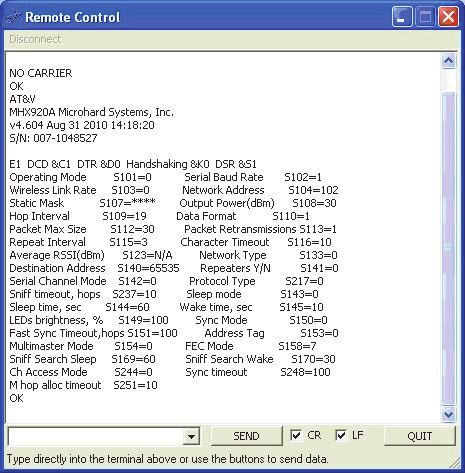
2. Start Remote Control and on
the UHF Radio tab click
Advanced.
This takes the radio offline,
passes through to the radio
data port, and presents the
current radio configuration
(shown at right).
The static mask is parameter
S107 and is shown in the
output as:
Static Mask S107=****
3. Type ATS107=xxxxxxxx in
the drop-down box and then
press Enter (or click SEND) to
change the static mask, where
xxxxxxxx represents the
static mask you want to use.
If successfully set, the radio
will reply with OK.
A320/321 User Guide 27 PN 875-0315-000 Rev A1Chapter 3: Operating the A320/321
4. Send the command AT&W to save the settings.
5. Click QUIT to return to normal operating mode.
Note: To remove the static mask (remove encryption) repeat the above procedure but
in step 4 type ATS107= in the drop-down box (do not type anything after the “=”).
Setting the Static Mask Using a Terminal Window
1. Connect to the A320/321 on Port A.
2. Start the terminal program on your PC. Make sure the baud rate of your PC
port matches that of the A320/321.
3. Send the command $JRELAY,PORTC,$MENUREPLY,A
4. Send the command $JRELAY,PORTC,$JRADIO,PROGRAMMODE to take the
radio offline, pass through to the radio data port, and present the current
radio configuration.
The static mask is parameter S107 and is shown in the output as:
Static Mask S107=****
5. Type ATS107=xxxxxxxx to change the static mask:
where xxxxxxxx represents the static mask you want to use. If successfully
set, the radio will reply with OK.
6. Send the command AT&W to save the settings.
7. Type QUIT (uppercase) to return to normal operating mode.
A320/321 User Guide 28 PN 875-0315-000 Rev A1Chapter 3: Operating the A320/321
Typical Distance Performance
Distance performance is dependent on several factors including:
• Base station antenna height
• Base station antenna gain
• Cable losses
• Base station transmit power
• Rover antenna gain
• Rover antenna height
• Receiver (rover) sensitivity
• Terrain
Hemisphere GPS’ high performance 400 MHz radio solution, when properly installed,
can provide up to 30 km of RTK coverage from one base station location. Figure 3-5
approximates the distance performance you can expect.
Figure 3-5: Typical RTK distance performance vs. base station antenna
height above ground
A320/321 User Guide 29 PN 875-0315-000 Rev A1Chapter 3: Operating the A320/321
The expected range is based on the following assumptions:
• Gently rolling hills
• Medium to low vegetation
• High quality, low loss RF cables at base station
• Base station uses Hemisphere GPS recommended 5 dBi antenna
• Base station Tx power is set to 3 W
• Rover antenna height is 3 m above ground level
• Frequency of operation is 450 MHz
• Mode of operation is PC1 (9600 bps GMSK, FEC ON)
As shown in Figure 3-5 base station antenna height is key to RTK performance. When
installing your base station, find a location on a structure, preferably at the highest
elevation available.
At 2m (6ft) base antenna height above ground, typical RTK distance performance is
approximately 8 km (5 mi). However, as you raise the base station antenna, this range
improves dramatically. At 20 m (65 ft) above ground level, rovers can expect to
typically receive RTK corrections at distances up to about 28 km (17 mi).
It is important to use high quality RF cable at the base station. Hemisphere GPS
provides high-quality RF cables in lengths of 15, 30, or 45 m.
Normally, the A321 will be located close to ground level, while the 400 MHz UHF
antenna will be mounted on a structure several meters above ground. This requires a
fairly long run of cable. Figure 3-6 illustrates the typical degradation in distance
performance (for four different base station antenna heights) as you use longer runs
of RF cable.
Typical Base-Rover Communication Range vs. Cable Length
Based on CCIR Path Loss Model - Plots show distance vs. cable length for four different
base antenna heights. Transmitter is 450 MHz at 3 W. Rover antenna height is 3 m.
Figure 3-6: Typical RTK distance performance vs. RF cable length at base
station for four base station antenna heights above ground
A320/321 User Guide 30 PN 875-0315-000 Rev A1Chapter 3: Operating the A320/321
Configuring Your A320/321 900 MHz
Microhard Radio
Setting the Radio Mode of Operation
The radio mode refers to a number of Hemisphere GPS-proprietary modes that are
optimized for certain message types and environments. See Table 3-4 on page 32 for
more information on supported radio modes.
Note: The following steps show how to use Remote Control software to set the mode.
Follow the same steps if using the actual menu on the A321 to set its mode.
Complete the following steps to set the radio mode:
Step Base Station Screen Item Rover Screen Item
Base Station
1. On the Top menu scroll
to and select Base
Station.
Rover
1. On the Top menu scroll
to and select RTK.
2. Scroll to (if necessary)
and select Radio.
A320/321 User Guide 31 PN 875-0315-000 Rev A1Chapter 3: Operating the A320/321
Step Base Station Screen Item Rover Screen Item
3. Scroll to and select
Mode.
4. Use the Up Arrow and
Down Arrow buttons
to display the desired
mode and press Enter
to select the mode.
Table 3-4 describes the available Hemisphere GPS-proprietary radio modes.
Hemisphere GPS recommends FAST mode for most applications.
Note: The Microhard MHX920-FS 900 MHz radio is proprietary and will not
communicate with other RTK manufacturers’ equipment.
Table 3-4: 900 MHz Microhard radio modes
Mode Description Comment
SLOW 19200 bit/s RF link rate Compatible with previously-released MHX920-SL1
with forward error (Part No. 808-1003-000) radio kit. Lowest data
correction (FEC) throughput of all the modes. Not recommended for
new installations.
SLOW is required for use on older 900 MHz radios
available from Hemisphere GPS.
SLOW2 19200 bit/s RF link rate Improved data throughput over SLOW mode. Suitable
with no FEC for use in low-noise environments with A320/321.
FAST 115200 bit/s RF link Superior data throughput allows RTK messages to be
rate with no FEC rebroadcast multiple times per second. Provides the
best performance in most applications.
FAST is required for GLONASS on the A320/A321.
A320/321 User Guide 32 PN 875-0315-000 Rev A1Chapter 3: Operating the A320/321
Setting the Channel
You can set the channel to any value between 1 and 100.
Each A321 base station and A320 rover in a network must be configured to operate on
the same channel.
Note: The following steps show how to use Remote Control software to set the
channel. Follow the same steps if using the actual menu on the A321 to set its channel.
Complete the following steps to set the channel:
Step Base Station Screen Item Rover Screen Item
Base Station
1. On the Top menu scroll
to and select Base
Station.
Rover
1. On the Top menu scroll
to and select RTK.
2. Scroll to (if necessary)
and select Radio.
A320/321 User Guide 33 PN 875-0315-000 Rev A1Chapter 3: Operating the A320/321
Step Base Station Screen Item Rover Screen Item
3. Scroll to and select
Channel.
4. Use the Up Arrow and
Down Arrow buttons
to display the desired
channel and then press
Enter.
Note: When you press Enter to set the last digit, the channel is set and the select indicator
changes to the display indicator (you can now use the Up Arrow and Down Arrow buttons
to highlight other Radio options such as Type and RSSI).
Setting the Power
Note: The following steps show how to use Remote Control software to set the
power. Follow the same steps if using the actual menu on the A321 to set its power.
A320/321 User Guide 34 PN 875-0315-000 Rev A1Chapter 3: Operating the A320/321
Complete the following steps to set the power:
Step Base Station Screen Item Rover Screen Item
Base Station
1. On the Top menu scroll
to and select Base
Station.
Rover
1. On the Top menu scroll
to and select RTK.
2. Scroll to (if necessary)
and select Radio.
3. Scroll to and select
Power.
4. Use the Up Arrow and
Down Arrow buttons
to display the desired
power and press Enter
to select the power.
A320/321 User Guide 35 PN 875-0315-000 Rev A1Chapter 3: Operating the A320/321
The Microhard MHX920-FS radio in the A321 is capable of transmitting at an output
power ranging from 0.1 W (20 dBm) up to 1 W (30 dBm) in 1 dB increments.
Hemisphere GPS recommends that you set the power to the maximum (1 W / 30 dBm)
for most applications.
Table 3-5: Typical A320/321 power consumption
Radio TX Power Typical Total A321 Power Typical Battery Discharge
Setting Consumption Time of 18Ah SLA Battery
20 dBm (0.1 W) 7.2 W 31 hours
27 dBm (0.5 W) 9.0 W 25.0 hours
30 dBm (1 W) 10.4 W 21.5 hours
Receive mode only 5.7 W 39 hours
Note: Typically the rover (A320) is always in receive mode and the base station (A321) is
always in transmit mode.
Checking VSWR
Voltage standing wave ratio (VSWR) provides an
indication of any RF cabling or antenna problems and
can be read on the base station menu interface.
VSWR has the following characteristics:
• The lower the number the better.
• Anything below 2 generally indicates the
cabling and antenna are installed correctly.
• If the value is above 2, check that the cable and antenna are securely
installed and that there is no visible damage.
The VSWR reading is updated approximately every 30 seconds.
Checking RSSI
Received signal strength indicator (RSSI) is a status
update of the strength of the signal received at the
rover, and can be read on the rover’s menu interface.
• The higher the number the better (for
example, -90 is better than -100).
• Typically, an RSSI of -100 and better is
acceptable for reliably receiving RTK
messages from the base station.
• If the value is below -100, steps should be taken to improve signal strength.
The best way to do this is to raise the height of the base station antenna.
A320/321 User Guide 36 PN 875-0315-000 Rev A1Chapter 3: Operating the A320/321
Operating the A320
Initial startup may take from 5 to 15 minutes, depending on your geographic location.
For example, it may take up to 5 minutes to receive a full ionospheric map from SBAS
to ensure optimum accuracy.
1. Verify the A320 and all connected systems are
powered on. When you turn the switch on the
power cable to the “ON” position the red LED
illuminates (indicating power).
See “LED Indicators” on page 7 for more
information on the A320 LED indicators.
2. Enter a receiver authorization code (optional). Contact your dealer or
Hemisphere GPS Technical Support for details.
3. Configure GPS options. See “Operating the A321” below.
4. Activate L-band service (optional). Contact your L-band service provider for
details.
5. Wait for the A320 to converge on a differential
signal. A green LED indicates DGPS. You are
ready to begin using your A320.
Operating the A321
On startup the A321 displays the Top menu. You can access all the setup menus from
the Top menu. The A321 menu system is designed for easy setup and configuration of
the unit in or out of the field.
This section includes the following topics:
• Begin using the A321 (below)
• Operating modes - fixed base station vs. portable base station (page 40)
• Setting the A321 as a fixed base station (page 40)
• Setting the A321 as a portable base station (page 44)
• Setting an alternate reference point (page 44)
• Managing configurations (page 45)
• USB data logging (page 46)
A320/321 User Guide 37 PN 875-0315-000 Rev A1Chapter 3: Operating the A320/321
Begin Using the A321
Complete the following steps to begin using the base station:
Screen Item
Step
(when applicable)
1. Plan the base station location. The A321
base station automatically uses its current
location as the reference point. Place the base
station in a location:
• With an unobstructed view of the sky
• At least 50 meters (160 feet) from any
obstructions
5m
(16.4 ft)
50 m (160 ft)
Figure 3-7: Location of the base station
2. Select the desired radio channel/frequency.
Base and rover configurations must match (for
900 MHz radios you set the channel; for 400 MHz
radios you set the frequency).
a. On the Top menu, select Base Station >
Radio. The Radio screen displays the radio
manufacturer, version number, and channel/
frequency.
b. Press Enter to select the Channel field.
c. Use the Up Arrow and Down Arrow
buttons to select the desired channel and
then press Enter to save.
d. Select Back to return to the previous menu.
A320/321 User Guide 38 PN 875-0315-000 Rev A1Chapter 3: Operating the A320/321
Screen Item
Step
(when applicable)
3. Wait for RTK lock (maximum accuracy). The
screen will cycle through the following displays.
Note: It takes 3 - 5 minutes for the base station
to achieve RTK lock in an unknown location. It
typically takes the base station less than 60 Countdown to
position lock
seconds to achieve RTK lock in a known location.
You are ready to use your A321 base station.
Position lock
GPS Position
Status screen
A320/321 User Guide 39 PN 875-0315-000 Rev A1Chapter 3: Operating the A320/321
Base Station Operating Modes
The A321 can operate in two base station modes:
• Fixed (permanent) base station mode
Typical Use: If year-after-year A-B line repeatability is expected for controlled
traffic farming, you must use this option from the first use.
• Portable base station mode
Typical Use: Quick and easy solution for temporary job or one-time-only
contract site.
A fixed location ensures the A321 uses the same reference coordinates every time and
they do not unintentionally change; otherwise, an unwanted jump in the rover’s offset
position from one RTK session to the next may occur (such as a tractor following an
A-B line that is offset by several centimeters up to several meters from one RTK
session to the next).
Fixed mode is intended for an A321 that is permanently mounted in a fixed location
(such as on a radio tower or other permanent structure), where you are satisfied with
its coverage and you will use it for RTK coverage of the same area from day to day,
season to season.
If you install the A321 within 50 m of the fixed coordinates, it will use these reference
coordinates for its RTK solution. The reference coordinates remain the same (are not
affected by a power cycle or excessive drift in GPS solution) until you manually
change them. The A321 will never use an alternate reference location. If the current
solution drifts more than 50 m from these reference coordinates the A321 stops
broadcasting the RTK message.
As shown in Figure 3-8, you use the FixedLoc menu setting to set your A321 as a fixed
base station (set to YES) or a portable base station (set to NO).
Fixed base station mode Portable base station mode
Figure 3-8: Operating modes (FixedLoc setting)
To navigate to the FixedLoc setting:
• From the Top menu, select Base Station > Reference > FixedLoc.
Setting the A321 as a Fixed Base Station
When setting a fixed location for your base station you have the following options:
• Entering new reference information manually
• Using the unit’s current position
• Using an average of the unit’s current position (averaging occurs for 300 sec)
Note: In areas of ionospheric activity re-averaging the unit’s position (third bullet
above) may provide the most reliable location information.
A320/321 User Guide 40 PN 875-0315-000 Rev A1Chapter 3: Operating the A320/321
Manually Entering Fixed Coordinates
You can manually enter base station coordinates before or after installing the A321.
For example, if you know the exact installation location and you first enter the
coordinates, the person installing the A321 can simply install it and power it up.
To fix the base station location to a manually-entered coordinates:
Screen Item
Step
(when applicable)
1. On the Top menu, select Base Station >
Reference > FixedLoc.
2. Use the Up Arrow or Down Arrow button to
change the value to Yes and then press Enter.
Note: For information on entering/editing
values see “Navigating the Menus and Selecting
Menu Items” on page 18.
3. Select Enter New. Lt, Ln, and Hgt are displayed
with Lt highlighted.
4. Enter the desired coordinate information:
latitude (Lt), longitude (Ln), and height (Hgt).
5. Scroll to and select Set Reference. The screen
changes to show the Time To Go and then Time
To Go changes to Converged (if the unit
converges on the coordinates).
A320/321 User Guide 41 PN 875-0315-000 Rev A1Chapter 3: Operating the A320/321
Setting the Base Station Fixed Location to Its Current Location
Note: You should only use this option after the A321 is installed and has converged.
To set the base station fixed location as the current position:
Screen Item
Step
(when applicable)
1. On the Top menu, select Base Station >
Reference > FixedLoc.
2. Use the Up Arrow or Down Arrow button to
change the value from No to Yes and then press
Enter.
3. Scroll to and select Use Current Pos. The
screen changes to show the Time To Go and
then Time To Go changes to Converged (if the
unit converges on the coordinates).
Setting the Base Station Fixed Location to an Average of Positions
Note: You should only use this option after the A321 is installed.
The A321 re-averages its position for 5 minutes (300 seconds) and assigns this new position
to its permanent reference coordinates.
A320/321 User Guide 42 PN 875-0315-000 Rev A1Chapter 3: Operating the A320/321
To set the base station fixed location to an average of positions:
Screen Item
Step
(when applicable)
1. On the Top menu, select Base Station >
Reference > FixedLoc.
2. Use the Up Arrow or Down Arrow button to
change the value from No to Yes and then press
Enter.
3. Scroll to and select Re-Average Pos. The
screen changes to show the Time To Go and the
A321 counts down from 300 seconds to zero,
after which Time To Go changes to Converged (if
the unit converges on the coordinates).
A320/321 User Guide 43 PN 875-0315-000 Rev A1Chapter 3: Operating the A320/321
Setting the A321 as a Portable Base Station
To set the A321 as a portable base station:
Screen Item
Step
(when applicable)
1. On the Top menu, select Base Station >
Reference > FixedLoc.
2. Use the Up Arrow or Down Arrow button to
change the value from Yes to No and then press
Enter.
Setting an Alternate Reference Point
To set an alternate reference point:
Screen Item
Step
(when applicable)
1. On the Top menu, select Base Station >
Reference > Set New Reference > Enter
New.
2. Enter the desired coordinates.
A320/321 User Guide 44 PN 875-0315-000 Rev A1Chapter 3: Operating the A320/321
Managing Configurations
The A321 Configuration Wizard allows you to:
• Save a configuration
• Return to a saved configuration
• Delete a saved configuration
Saving a Configuration
To save a configuration:
Screen Item
Step
(when applicable)
1. On the Top menu, select Config Wizard >
Proceed Wizard > Create New.
2. Select Enter Name, use the Up Arrow and
Down Arrow buttons to enter a name, then
press Enter.
3. Scroll to and select Save to Location.
4. Scroll to the desired location (such as Not
Used1) and press Enter to save.
Returning to a Saved Configuration
To return to a saved configuration:
Screen Item
Step
(when applicable)
1. On the Top menu, select Config Wizard > Use
Previous.
A320/321 User Guide 45 PN 875-0315-000 Rev A1Chapter 3: Operating the A320/321
Screen Item
Step
(when applicable)
2. Scroll to the desired configuration and press
Enter to select it.
Deleting a Saved Configuration
To delete a saved configuration:
Screen Item
Step
(when applicable)
1. On the Top menu, select Config Wizard >
Delete Saved.
2. Select the desired configuration and press Enter
to delete it.
Note: Once you press Enter, the saved
configuration is permanently deleted.
USB Data Logging
When you insert a USB flash drive into the A321, the Data Logging menu indicates
you can start recording (logging data) and displays the free space on the flash drive
(see Figure 3-9). When you start logging data the “Start Recording” indicator changes
to “End .”
With no USB flash drive inserted With USB flash drive inserted
Figure 3-9: USB flash drive indicators on Data Logging menu
Stop data logging before removing the USB flash drive from the A321.
Failure to do so may result in a loss of data.
A320/321 User Guide 46 PN 875-0315-000 Rev A1You can also read