PROGRAM FOR TRENCHING AND EXCAVATION - THE UNIVERSITY OF TEXAS AT TYLER 2021 - UT Tyler
←
→
Page content transcription
If your browser does not render page correctly, please read the page content below
THE UNIVERSITY OF TEXAS AT TYLER

       PROGRAM FOR
      TRENCHING AND
        EXCAVATION

               2021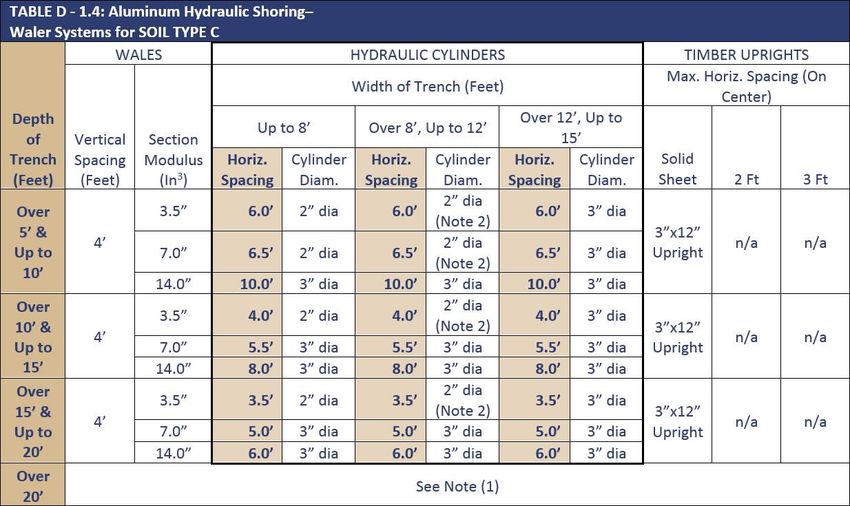
2

Introduction: .....................................................................................................................................3
Purpose: ............................................................................................................................................3
Application: .......................................................................................................................................3
Definitions: ........................................................................................................................................3
Excavation Procedures: ......................................................................................................................6
Protective Systems:.......................................................................................................................... 10
Contractor Information: ................................................................................................................... 14
Training: .......................................................................................................................................... 15
Record Retention: ............................................................................................................................ 15
Annual Compliance Review: ............................................................................................................. 15
Revisions ......................................................................................................................................... 15
Appendix A: ..................................................................................................................................... 16
Appendix B: ..................................................................................................................................... 17
Appendix C: ..................................................................................................................................... 23
Appendix D: ..................................................................................................................................... 26
Appendix E: ..................................................................................................................................... 29
Appendix F: ..................................................................................................................................... 30
3

Introduction:

The University of Texas at Tyler Environmental Health and Safety department has developed
this Trenching and Excavation Safety Program to ensure a safe work environment and to
protect the health and safety of University Staff and any contractors or vendors working on
University property. This program was written with guidance from OSHA guidelines, the
University of Texas System Construction Safety Program, and on-site Job Hazards Analyses.

Purpose:
The purpose of the University Trenching and Excavation Program is to establish requirements
for safe trenching, excavating and shoring activities at The University of Texas at Tyler. The
intent is to ensure any activity involving trenching and excavating is conducted in a manner to
minimize risk to employees, property, students, visitors and contractors.

Application:
This program applies to work performed by any UT Tyler employee, student, or contractor
performing work that involves trenching and excavation. This program sets forth the practices
required for trenches or excavations with a depth of four feet or greater along any portion of its
length that will be entered by anyone on UT Tyler’s campus. All excavations or trenches 4 feet
or greater in depth shall be appropriately benched, shored, or sloped according to the
procedures and requirements set forth in this policy. Excavations or trenches 20 feet deep or
greater must have a protective system designed by a registered professional engineer.

Definitions:

Aluminum Hydraulic Shoring: a manufactured shoring system consisting of aluminum hydraulic
cylinders (cross braces) used with vertical or horizontal rails designed to support sidewalls of an
excavation.

Bell-Bottom Pier Hole: a shaft or footing excavation, the bottom of which is made larger than
the cross section above to form a bell shape.

Benching: a method of protecting workers from cave-in by excavating the sides of an
excavation to form one or more horizontal steps, usually with vertical or near-vertical surfaces
between levels.

Cave-in: the movement of soil or rock into an excavation, or the loss of soil from under a trench
shield or support system, in amounts large enough to entrap, bury, or otherwise injure and
immobilize a person.

Competent Person: one who has been trained to identify existing and predictable hazards in
4

the workplace, or working conditions that are unsafe for workers, and who has the authority to
have these hazards corrected, stopping the work if necessary. The Designated Supervisor of an
excavation is chosen by the department and serves as the Competent Person for the purposes
of this program.

Cross Braces: the horizontal members of a shoring system installed from side to side of the
excavation. The cross braces bear against either uprights or wales.

Excavation: any man-made cut, cavity, trench, or depression in an earth surface, formed by
earth removal.

Faces or Sides: the vertical or inclined earth surfaces formed as a result of excavation work.

Failure: the movement or damage through breakage, displacement or permanent deformation
of a structural member or connection of equipment that makes it unable to support loads.

Hazardous Atmosphere: an atmosphere that is explosive, flammable, poisonous, corrosive,
oxidizing, irritating, oxygen deficient, toxic, or otherwise harmful, that may cause death, illness,
or injury.

Kick out: the accidental movement or failure of a cross brace.

Layered Geological Strata: where soil types are configured in layers. The soil should be
classified on the basis of the weakest soil layer classification. Each layer may be classified
individually if a more stable layer lies below a less stable layer. (See Soil Types)

Protective System: a method of protecting workers from cave-ins or any other failures, from
material that could fall or roll from an excavation face into an excavation, or from the collapse
of adjacent structures. Protective systems include support systems, sloping and benching
systems, shield systems and other systems that provide the necessary protection.

Ramp: an inclined walking or working surface that is used to gain access to one point from
another. A ramp may be constructed from earth or from structural materials such as steel or
wood.

Registered Professional Engineer: a person who is registered as a Professional Engineer in the
state of Texas.

Soil Types:

Type A - Most stable: clay, silty clay and hardpan. No soil is Type A if it is fissured, is subject to
vibration, has previously been disturbed or has seeping water.

Type B - Medium stability: silt, sandy loam, medium clay and unstable dry rock. Previously
5

disturbed soils, except those that would be classified as Type C. Also, soil that meets the
requirement of Type A soil but is fissured or subject to vibration.

Type C - Least stable; gravel, sand, loamy sand, soft clay, submerged soil or dense unstable
rock, or soil from which water is freely seeping.

Sheeting: the members of a shoring system that retain the earth in position and in turn are
supported by other members of the shoring system.

Shield (Shield System): a structure used in an excavation that is able to withstand cave-ins and
which will protect those working within the shield system. Shields can be permanent structures
or portable units moved along as work progresses. Shields used in trenches are usually referred
to as "trench boxes" or "trench shields."

Shoring (Shoring System): a structure that is built or put in place to support the sides of an
excavation and designed to prevent cave-ins.

Sloping (Sloping System): sloping the sides of the excavation away from the excavation to
protect employees from cave-ins. The required slope or angle of incline will vary with soil type,
weather and surface or near surface loads that may affect the soil in the area of the trench
(such as adjacent building, vehicles near the edge of the trench).

Stable Rock: natural solid mineral material that can be excavated with vertical sides that will
remain intact while exposed.

Structural Ramp: a ramp built of steel or wood, usually used for vehicle access. Ramps made of
soil or rock are not considered structural ramps.

Support System: a structure such as underpinning, bracing, or shoring, which provides support
to an adjacent structure, underground installation, or the sides of an excavation.

(TSF): tons per square foot

Uprights: the vertical members of a trench shoring system placed in contact with the earth and
usually positioned so that individual members do not contact each other. Uprights placed so
that individual members are closely spaced, in contact with or interconnected to each other,
are often called "sheeting."

Wales: horizontal members of a shoring system placed in the direction of the excavation face
whose sides bear against the vertical members of the shoring system or earth (the uprights or
sheeting).
6

Excavation Procedures

Underground Utility Impact

   •   Prior to any excavation or trenching operations, the project supervisor must determine
       if underground utilities may be present or impacted by the project. A pre-work site
       inspection should be completed by the site supervisor, utilities personnel,
       Environmental Health and Safety, and Facilities Management.
   •   Any underground utilities (gas, sewer, data, water, and electric lines) must be clearly
       marked on the surface prior to any excavating. (refer to table 1 for utility markings)
   •   If utilities are present or impacted by the project, the designated supervisor must
       arrange to have the utilities protected, removed or relocated as directed by UT Tyler
       Facilities.
   •   Excavation must be done in a manner that does not endanger the underground
       installations or those engaged in the work. Barricades, shoring, suspension or other
       means as necessary can be utilized to project utilities left in place during
       excavations/trenching.

                          Table 1: Underground Utility Marking Colors
              RED – Electric power lines, cable, conduit and lighting cables
              YELLOW – Gas, oil, steam, petroleum or gaseous materials
              ORANGE – Communication, alarm, signal lines, cable, or conduit
              BLUE - Water
              PURPLE – Reclaimed water, irrigation, and slurry lines
              GREEN – Sewers and drain lines
              PINK – Temporary survey markings
              WHITE – Proposed excavation

Stability of Adjacent Structures

   •   The supervisor must take precautions as needed to protect workers, nearby buildings or
       other structures. A Registered Professional Engineer should evaluate these structures
       and recommend precautions such as shoring, bracing, or underpinning. The supervisor
       must ensure that the recommendations of the engineer are carried out. Plans that
       outline the design of such precautions approved by the engineer will be maintained on
       site while the work is in progress.

Protection of the Public

   •   Barricades, walkways, lighting and signs must be provided for the protection of the
       public before the start of excavation operations. Guardrails, fences or barricades will be
       provided adjacent to walkways, driveways and other pedestrian or vehicle
       thoroughfares.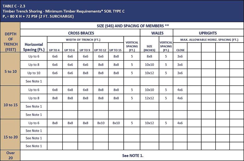
7

Protecting Workers in Excavations

   •   The Supervisor must assure that workers are protected from hazards that may arise
       during excavation work.
   •   Stairs, ladders or ramps should be provided when workers enter excavations over four
       (4) feet deep. Two (2) or more means of exit will be provided if the excavation is more
       than 20 feet in length. A means of exit will be provided every 25 feet of trench length.
   •   A competent person, qualified in structural design, will design structural ramps used for
       egress or access of equipment. The ramp will be constructed in accordance with the
       design. Ramps with two (2) or more structural members will have the structural
       members that are uniform thickness and connected together to prevent displacement
       and will not present a tripping hazard. Ramps must have a slope of 20 degrees or less.
   •   Those workers exposed to vehicular traffic will wear warning vests made of high
       visibility material.
   •   No one will work underneath loads handled by lifting or digging equipment. Workers
       will stand away from any vehicle being loaded or unloaded to avoid being struck by any
       spillage or falling materials.
   •   A warning system will be used when mobile equipment is operated next to the edge of
       an excavation if the operator does not have a clear, direct view of the edge of the
       excavation.
   •   Materials and equipment should be kept at least two (2) feet from the edge of the
       excavation with the proper protective system in place.
   •   Spoil Piles that are less than four feet (4’) in height shall be at least two feet (2’) from
       the edge of any excavation. Spoil piles greater than four feet (4’) in height shall add one
       foot (1’) of distance from the excavation for every additional foot in height.
   •   Trench excavations should be backfilled at the end of each shift.

Hazardous Atmospheres and Confined Spaces

   •   Workers will not be permitted to work in hazardous and/or toxic atmospheres. Such
       atmospheres include those with the following:
          1. Atmospheric oxygen concentration below 19.5% or above 23.5%.
          2. A combustible gas concentration greater than 10% of the lower flammable limit.
          3. Concentrations of hazardous substances that exceed those specified in the
              Threshold.
          4. Limit Values (TLVs) for airborne contaminants established by the American
              Conference of Industrial Hygienists (ACGIH).
   •   The above hazards are typically monitored with a confined space 4-gas air monitoring
       meter. Additional information regarding confined space entry and air monitoring can be
       found in the UT Tyler Confined Space Safety Program, available at
       https://www.uttyler.edu/safety/
   •   If there is any possibility that the trench or excavation could contain a hazardous
       atmosphere, the Designated Supervisor will ensure that atmospheric testing is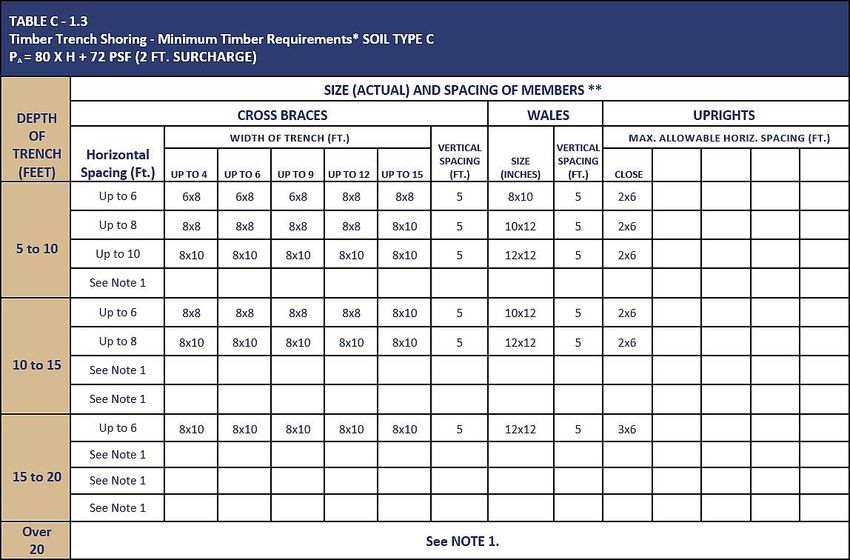
8

       conducted before worker entry and continuously during work. Excavations near
       underground storage tanks or those that contain gas pipelines will be monitored.
       Suitable precautions will be taken as necessary to protect workers. These precautions
       may include the following:
           1. Engineering controls such as ventilation;
           2. Respiratory protection; those required to wear respiratory protection must be
              enrolled in the University of Texas at Tyler Protection Program. Enrollment in the
              program requires workers to:
                  A. Complete respiratory protection training (EH&S provides training for air
                     purifying respirators);
                  B. Obtain a fit test provided by EH&S;
                  C. Complete a medical examination; and
                  D. Maintain annual re-certification.

Fall Protection: Fully Body Harness and Lifelines

   •   Trenches and excavations, which are classified as permit required confined spaces
       (those where atmospheric hazards exist) may be required to have rescue equipment on
       hand in the event of an emergency.
           1. Rescue equipment can include a full body harness and lifeline to be used to raise
              personnel safely from an excavation during an emergency.
           2. For additional information on rescue equipment used during confined space
              emergencies, consult the UT Tyler Confined Space Entry Safety Program.
   •   Another instance when fall protection may be necessary is for personnel working
       outside the excavation/trench where a fall hazard exists.
           1. If a fall hazard of 6-feet or more is present on the side of an excavation/trench,
              personnel standing on the top of the trench are in a position where a fall hazard
              exists and should be tied off using a full body harness and either a retractable
              lifeline or lanyard of appropriate length.
           2. For additional information regarding protection from fall hazards, please consult
              the UT Tyler Fall Protection Safety Program.

Personal Protective Equipment

   •   The Designated Supervisor will ensure that all workers wear required personal
       protective equipment (PPE) as detailed below. Hardhats, safety eyewear, gloves,
       hearing protection and fall protection devices will be furnished by the employee’s
       supervisor. The employer must ensure that anyone conducting work in excavations
       wears PPE approved by the American National Standards Institute (ANSI).
   •   The following PPE is required during excavation/trenching activities:
          1. Personnel working in trenches or excavations will wear ANSI approved hardhats
               at all times.
          2. Personnel working in trenches or excavations will wear ANSI approved steel-toed
               shoes or boots.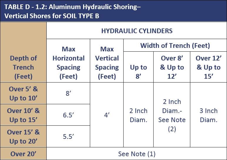
9

          3. Where there is potential for exposure to flying fragments, dust or other
             materials produced by drilling, sawing, sanding, grinding and similar operations
             will wear ANSI approved safety glasses with side shields.
          4. Where there is a potential for exposure to hazards produced through welding,
             cutting, or brazing must wear approved eye protection or a welding face
             shield/helmet and must be accompanied by a hot work permit supplied by the
             university’s Environmental Health & Safety.
          5. Where fall hazards exist; or where rescue operations may be necessary,
             personnel must wear a full body harness and be tied off at all times to an
             approved lifeline or anchor point.
          6. Hand protection must be made available to employees based on the hazards of
             the work being performed.
          7. To determine the appropriate PPE to be utilized during a specific excavation or
             trenching activity, the supervisor should conduct a job-hazard assessment and
             ensure all hazard are addressed prior to personnel entering a trench.

Walkways and Guardrails

   •   Walkways must be provided where workers or equipment are allowed to cross over
       excavations.
   •   Guardrails must be provided on walkways used by the general public regardless of the
       height above the excavation.
   •   Guardrails must be provided on walkways used only by on-site personnel if the walkway
       is six (6) feet or more above lower levels. This will protect personnel on the top/edge of
       an excavation from a fall hazard and eliminate the need for a full body harness and tie
       off when working outside of the trench.
   •   Guardrails with toe boards must be provided when/if workers pass below a walkway.

Hazards Associated with Water Accumulation

   •   Anytime a trench/excavation exists, there is a potential for water to accumulate, which
       may pose additional hazards to personnel entering the trench/excavation.
   •   Personnel may not work in excavations with standing water or where water is collecting
       unless the Supervisor gives prior approval or instruction.
   •   Methods for controlling water accumulation should be provided and consist of the
       following if anyone must work in the excavation:
           1. Use of special support or shield systems approved by a Registered Professional
               Engineer.
           2. Water removal equipment, such as a water pump, used and monitored by the
               Supervisor or a designated employee.
           3. Use of safety harnesses and lifelines.
   •   Work in excavations during a rainstorm is prohibited.
   •   Trenches must be inspected by the Supervisor after each rain and before anyone is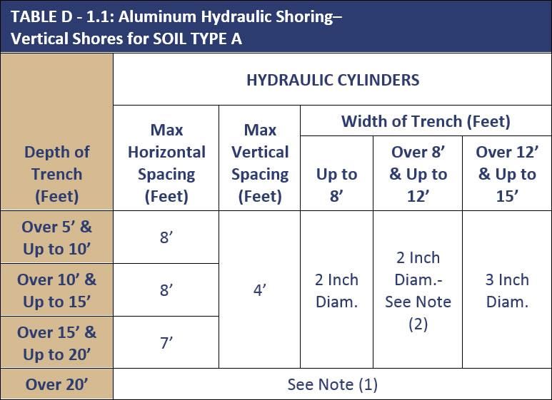
10

       permitted to re-enter the excavation.

Protection of Workers from Falling Objects

   •   The Supervisor must ensure that workers are protected from loose rock or soil that
       could fall or roll from an excavation face. Protective measures may consist of:
           1. Scaling to remove loose material;
           2. Installation of barricades such as wire mesh or timber as needed to stop and
               contain falling material.
           3. Sloping may be used instead of barricades when practical.
   •   Workers must be protected from excavated materials, equipment or other objects that
       could pose a hazard by falling or rolling into excavation. These materials or equipment
       must be maintained at least two (2) feet from the edge of the excavation or otherwise
       restrained. Materials piled, grouped or stacked near the edge of an excavation must be
       stable and self-supporting.

Inspections

   •   The Supervisor must conduct daily inspections of excavations, adjacent area and
       protective systems for evidence that could result in a cave-in, failure of protective
       systems, hazardous atmospheres or other hazardous conditions.
   •   Inspections must be conducted before the start of work and as needed throughout the
       shift. Inspections will also be made after every rainstorm.
   •   Inspections are only required when the trench will be or is expected to be occupied.
   •   When a hazardous condition is found, exposed workers will be removed from the area
       until precautions have been taken to assure their safety.
   •   Inspections must be documented in writing and kept on-site.

Protective Systems

Selection of Protective Systems

   •   Personnel working in an excavation must be protected from cave-ins by using an
       adequate sloping and benching system; or an adequate support or protective system.
   •   The only exceptions are when the excavation is made entirely in stable rock or the
       excavation is
           1. Less than four (4) feet in depth where examination of the ground by the
               Supervisor provides no indication of a potential cave-in.
   •   Excavations 20 feet or less: The decision tree in Appendix F (See appendix F of this Plan)
       will be used to determine the appropriate section of protective systems used in
       excavations 20 feet or less in depth.
   •   Excavations greater than 20 feet in depth: A registered professional engineer must
       design all excavations greater than 20 feet in depth.
11
Soil Classification
• In order to design the most appropriate protective system, the Supervisor must
determine the soil type using a visual test with one or more manual tests as required by
the university. Additional information regarding soil classification can be found in
Appendix A – Soil Classification.
1. Visual Test
A. During the visual test, the entire excavation site including the soil
adjacent to the site must be observed.
B. The Supervisor will check for crack-line openings along the failure zone
that indicate tension crack and observe the open side of the excavation
for indications of layered geologic structuring.
C. Other conditions to look for are signs of bulging, boiling, or sloughing, as
well as signs of surface water seeping from the side of the excavation or
from the water table.
2. Manual Tests
A. Thumb Penetration Test
I. The thumb penetration test can be used to estimate the
unconfined compressive strength of cohesive soils. (This test is
based on the thumb penetration test described in American
Society for Testing and Materials (ASTM) Standard designation
D2488 - "Standard Recommended Practice for Description of Soils
(Visual - Manual Procedure).") Type A soils with an unconfined
compressive strength of 1.5 psf can be readily indented by the
thumb; however, they can be penetrated by the thumb only with
very great effort. Type C soils with an unconfined compressive
strength of 0.5 psf can be easily penetrated several inches by the
thumb and can be molded by light finger pressure. This test
should be conducted on an undisturbed soil sample, such as a
large clump of spoil, as soon as practicable after excavation to
keep to a minimum the effects of exposure to drying influences. If
the excavation is later exposed to wetting influences (rain,
flooding), the classification of the soil must be changed
accordingly.
B. Dry Strength Test
I. If the soil is dry and crumbles on its own or with moderate
pressure into individual grains or fine powder, it is granular (any
combination of gravel, sand, or silt). If the soil is dry and falls into
clumps which break up into smaller clumps, but the smaller
clumps can only be broken up with difficulty, it may be clay in any
combination with gravel, sand or silt. If the dry soil breaks into
clumps which do not break up into small clumps and which can
only be broken with difficulty, and there is no visual indication the
soil is fissured, the soil may be considered un-fissured. Also,12
plasticity or Wet Thread Test.
II. Mold a moist or wet sample of soil into a ball and attempt to roll
it into threads as thin as 1/8-inch in diameter. Cohesive material
can be successfully rolled into threads without crumbling. For
example, if at least a two-inch (50 mm) length of 1/8-inch thread
can be held on one end without tearing, the soil is cohesive.
Specialized soil strength testing equipment including a penetrometer, shear vane or torvane
may also be used to determine the unconfined compression strength of soils.
Types of Protective Systems
The following systems can be used to protect workers from cave-ins in trenches of more than
four (4) feet deep. The Supervisor should select the method of protection that is most suitable
for the particular job site, taking into consideration soil type and surrounding structures. If the
soil is not classified, then the excavation must be sloped at an angle not steeper than one and a
half horizontal to one vertical.
Sloping (See Appendix B – Sloping and Benching for additional information)
• Maximum allowable slopes for excavations less than 20 feet deep based on soil type and
angle to the horizontal are as follows:
Soil Type Height/Depth Ratio Slope Angle
Stable Rock Vertical 90°
Type A ¾:1 53°
Type B 1:1 45°
Type C 1½:1 34°
Benching (See Appendix B – Sloping and Benching for additional information)
• There are two types of benching:
1. “Single, One level or step,” not exceeding 4 feet in height.
2. “Multiple, more than one level or step” each not to exceed four feet in height.
• Benching can be used in conjunction with simple sloping. Benches must be below the
maximum allowable slope for that soil type.
• Benching is not permitted in Type C soil.
Shoring
Shoring is used when the location or depth of the trench makes sloping back to the maximum
allowable slope impractical. There are two basic types of shoring: timber and aluminum
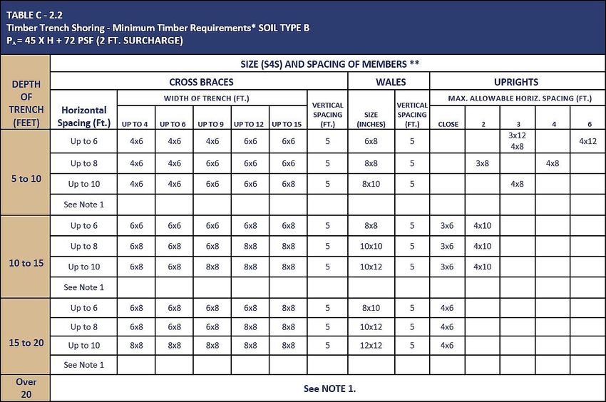
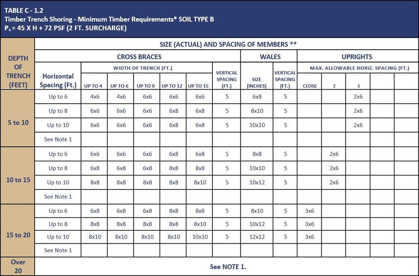
hydraulic. See Appendices C and D for additional information regarding shoring.13
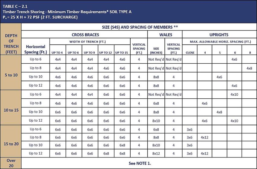
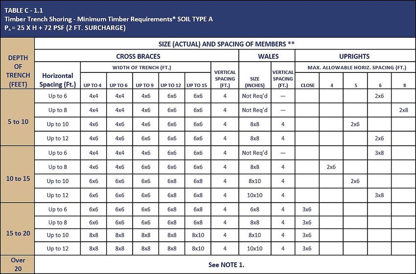
• Timber Shoring
1. The Supervisor will use the information in the tables of Appendix C of this plan -
Timber Shoring for Trenches to determine the appropriate manner to
incorporate timber shoring.
2. The members of the shoring system that are to be selected using the tables are
the cross braces, the uprights, and the “Wales” where Wales are required.
3. The Supervisor will select the size and spacing of members using the appropriate
table. The selection will be based on the depth and width of the trench where
the members are to be installed.
4. In most instances, the selection is also based on the horizontal spacing of the
cross braces.
5. Where a choice is available, the horizontal spacing of the cross braces must be
chosen before the size of any member can be determined.
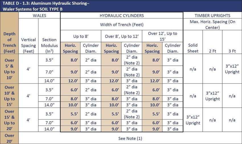
• Hydraulic Aluminum Shoring
1. Hydraulic shoring provides a critical advantage over timber shoring because
workers do not have to enter the trench to install them. They are also light
enough to be installed by one worker, they are gauge-regulated to ensure even
distribution of pressure along the trench line and they can be adapted easily to
various trench depths and widths.
2. Hydraulic Shoring Support Systems must be constructed and used in accordance
with all specifications, recommendations and limitations issued by the
manufacturer.
3. Hydraulic shores must be installed in accordance with Appendix D - Aluminum
Hydraulic Shoring for Trenches. (See Appendix D to this plan). The Supervisor
must use the tables in this standard to determine the maximum vertical and
horizontal spacing that may be used with various aluminum member sizes and
various hydraulic cylinder sizes.
4. All shoring must be installed from the top down and removed from the bottom
up. The Supervisor will inspect all hydraulic shoring at least once per shift for
leaking hoses and/or cylinders, broken connections, cracked nipples, bent bases,
and any other damaged or defective parts. This inspection will be documented in
writing. The top cylinder of hydraulic shoring will be no more than two feet from
the top edge of the excavation. Two feet of trench may be exposed beneath the
bottom of the rail or plywood sheeting, if used.
Shielding
• Shielding differs from shoring because instead of shoring up or otherwise supporting
the trench face, they are intended primarily to prevent cave-in of the trench walls.
Trench boxes are generally used in open areas but may be used in combination with
sloping and benching. For additional information regarding alternatives to shoring refer
to Appendix E.
• The following safety measures must be followed during shielding operations:
1. Inspect trench boxes for good condition before each use.14
2. Minimize the excavated area between the outside of the trench box and the face
of the trench.
3. Backfill the space between the trench box and the excavation side to prevent
lateral movement of the box.
4. Ensure the trench box is extending at least 18-inches above the surrounding area
if there is sloping toward the excavation. Providing a sloped area adjacent to the
box
5. Ensure the shields ride two feet above the bottom of the excavation provided
they are calculated to support the full depth of the excavation and there is no
caving under or behind the shield.
6. Modifications to the shield must only be completed or approved by the
manufacturer.
7. Workers must enter and leave the shield in a protected manner, such as by a
ladder.
8. Workers may not remain in the shield while it is being moved.
Design by a Professional Engineer
• A Registered Professional Engineer may design sloping, benching, shoring and shielding
systems. The design will be written and must include the following:
1. A plan indicating the sizes, types and configurations of the materials to be used
in the protective system.
2. The identity of the Registered Professional Engineer approving the design.
3. At least one copy of the design must be maintained at the job site during
construction of the protective system.
• A Registered Professional Engineer must approve all excavations more than 20 feet in
depth.
Contractor Information
• Contractors hired by the University to perform excavation or trenching operations must
have their own trenching safety policies that comply with applicable federal and state
OSHA regulations.
• Contractors must coordinate with Facilities and Environmental Health and Safety early
in the programming and development stages to determine their project's impact to
utilities and gain approval for all trenching and excavation activities indicating that the
impact to utilities has been reviewed and approved before bidding the work or
proceeding with excavation.
• The contractor must coordinate with UT Tyler the identification and marking of
underground utilities including sewer, telecommunication, gas, water, steam electric,
etc. The contractor will arrange to have these utilities protected, removed or relocated
as directed by the appropriate UT Tyler department.15
Training
• Training on the purpose, content and function of the Trenching and Excavation Safety
Program is required for all employees who participate in trenching/excavation
operations on UT Tyler property. Training can be obtained through EH&S. Records must
be kept showing training dates, attendance, items covered, and name of presenter.
• Authorized Employees
1. Authorized employees are those who have received proper training and have
been “authorized” by EH&S to conduct trenching/excavation operations when
necessary. Training for authorized employees shall include all applicable areas of
this program. Additional training outside of this written safety program and
training may be necessary including equipment specific training provided.
A. Affected Employees are those whose job may require being around trenches
and excavations and should include all applicable areas of this safety
program and training.
• Retraining
1. Retraining or additional training is required whenever:
A. There is a new or revised trenching/excavating procedure.
B. An authorized employee's job duties change regarding
trenching/excavating.
C. The Trenching and Excavation Program changes.
D. Additional unique hazards arise, such as new equipment or modified
processes.
E. Refresher training is recommended annually.
Record Retention:
Manufacturer’s instructions, inspection, and maintenance records must be kept for as long as
the equipment is in use. The trenching and excavation inspection records must be kept a
minimum of 3 years. Training records for all users must be kept at a minimum of 3 years.
Annual Compliance Review
The Environmental Health and Safety department will review the program annually to
determine how the program can be improved. EH&S will strive to keep all programs up to date,
with accurate information that employees, and outside contractors can rely on.
Revisions
Date Author/Reviewer Description/Reason for Change
5/4/2021 T Bay/ P Tate Reviewed for latest revision/updated
year/added revision section16
Appendix A - Soil Classification
Type A means cohesive soils with an unconfined compressive strength of 1.5 ton per square
foot (psf) (144 kPa) or greater. Examples of cohesive soils are: clay, silty clay, sandy clay, clay
loam and, in some cases, silty clay loam and sandy clay loam. Cemented soils such as caliche
and hardpan are also considered Type A. However, no soil is Type A if:
• The soil is fissured; or
• The soil is subject to vibration from heavy traffic, pile driving, or similar effects; or
• The soil has been previously disturbed; or
• The soil is part of a sloped, layered system where the layers dip into the excavation on a
slope of four horizontal to one vertical (4H: 1V) or greater; or
• The material is subject to other factors that would require it to be classified as a less
stable material.
Type B means:
• Cohesive soil with an unconfined compressive strength greater than 0.5 psf (48 kPa) but
less than 1.5 psf (144 kPa); or
• Granular cohesion less soils including: angular gravel (similar to crushed rock), silt, silt
loam, sandy loam and, in some cases, silty clay loam and sandy clay loam.
• Previously disturbed soils except those which would otherwise be classified as Type C
soil.
• Soil that meets the unconfined compressive strength or cementation requirements for
Type A, but is fissured or subject to vibration; or
• Dry rock that is not stable; or
• Material that is part of a sloped, layered system where the layers dip into the excavation
on a slope less steep than four horizontal to one vertical (4H: 1V), but only if the
material would otherwise be classified as Type B.
Type C means:
• Cohesive soil with an unconfined compressive strength of 0.5 psf (48 kPa) or less; or
• Granular soils including gravel, sand, and loamy sand; or
• Submerged soil or soil from which water is freely seeping; or
• Submerged rock that is not stable; or
• Material in a sloped, layered system where the layers dip into the excavation on a slope
of four horizontal to one vertical (4H: 1V) or steeper.
Unconfined compressive strength - means the load per unit area at which a soil will fail in
compression. It can be determined by laboratory testing, or estimated in the field using a
pocket penetrometer, by thumb penetration tests, and other methods.
Wet soil - means soil that contains significantly more moisture than moist soil, but in such a
range of values that cohesive material will slump or begin to flow when vibrated. Granular
material that would exhibit cohesive properties when moist will lose those cohesive properties
when wet.17
Appendix B – Sloping and Benching
Slope Configurations
(All slopes stated below are in the horizontal to vertical ratio)
B-1.1 Excavations made in Type A soil.
1. All simple slope excavation 20 feet or less in depth shall have a maximum allowable slope of ¾:1.
SIMPLE SLOPE -- GENERAL
Exception: Simple slope excavations which are open 24 hours or less (short term) and which are 12 feet or
less in depth shall have a maximum allowable slope of ½:1.
SIMPLE SLOPE -- SHORT TERM
2. All benched excavations 20 feet or less in depth shall have a maximum allowable slope of 3/4 to 1 and
maximum bench dimensions as follows:
SIMPLE BENCH18
Appendix B – Sloping and Benching (PG. 2)
MULTIPLE BENCH
3. All excavations 8 feet or less in depth which have unsupported vertically sided lower portions shall have a
maximum vertical side of 3½ feet.
UNSUPPORTED VERTICALLY SIDED LOWER PORTION -- MAXIMUM 8 FEET IN DEPTH)
All excavations more than 8 feet but not more than 12 feet in depth with unsupported vertically sided lower
portions shall have a maximum allowable slope of 1:1 and a maximum vertical side of 3½ feet.
UNSUPPORTED VERTICALLY SIDED LOWER PORTION -- MAXIMUM 12 FEET IN DEPTH)
All excavations 20 feet or less in depth which have vertically sided lower portions that are supported or
shielded shall have a maximum allowable slope of ¾:1. The support or shield system must extend at least 18
inches above the top of the vertical side.19
Appendix B – Sloping and Benching (PG.3)
SUPPORTED OR SHIELDED VERTICALLY SIDED LOWER PORTION
4. All other simple slope, compound slope, and vertically sided lower portion excavations shall be in
accordance with the other options permitted under § 1926.652(b).
B-1.2 Excavations Made in Type B Soil
1. All simple slope excavations 20 feet or less in depth shall have a maximum allowable slope of 1:1.
SIMPLE SLOPE
2. All benched excavations 20 feet or less in depth shall have a maximum allowable slope of 1:1 and
maximum bench dimensions as follows:20
Appendix B – Sloping and Benching (PG.4)
SINGLE BENCH
MULTIPLE BENCH
3. All excavations 20 feet or less in depth which have vertically sided lower portions shall be shielded or
supported to a height at least 18 inches above the top of the vertical side. All such excavations shall have a
maximum allowable slope of 1:1.
VERTICALLY SIDED LOWER PORTION
4. All other sloped excavations shall be in accordance with the other options permitted in § 1926.652(b).
B-1.3 Excavations Made in Type C Soil
1. All simple slope excavations 20 feet or less in depth shall have a maximum allowable slope of 1½:1.21
Appendix B – Sloping and Benching (PG.5)
SIMPLE SLOPE
2. All excavations 20 feet or less in depth which have vertically sided lower portions shall be shielded or
supported to a height at least 18 inches above the top of the vertical side. All such excavations shall have a
maximum allowable slope of 1½:1.
VERTICAL SIDED LOWER PORTION
3. All other sloped excavations shall be in accordance with the other options permitted in § 1926.652(b).
B-1.4 Excavations Made in Layered Soils
1. All excavations 20 feet or less in depth made in layered soils shall have a maximum allowable slope for
each layer as set forth below.
B OVER A22
Appendix B – Sloping and Benching (PG.6)
C OVER A
C OVER B
A OVER B
A OVER C
B OV23 Appendix C – Timber Shoring for Trenches
24

Appendix C – Timber Shoring for Trenches (PG. 2)
25

Appendix C – Timber Shoring for Trenches (PG. 3)
26

      Appendix D – Aluminum Hydraulic Shoring for Trenches

Figure NO. 1 – Vertical aluminum     Figure NO. 2 – Vertical aluminum
 hydraulic shoring (spot bracing)    hydraulic shoring (with plywood)

Figure NO. 3 – Vertical aluminum       Figure NO. 4 – Vertical aluminum
   hydraulic shoring (stacked)             hydraulic shoring (typical)
27 Appendix D – Aluminum Hydraulic Shoring for Trenches (PG. 2)
28

Appendix D – Aluminum Hydraulic Shoring for Trenches (PG. 3)
29

            Appendix E – Alternatives to Timber Shoring

Figure NO. 1 – Aluminum Hydraulic         Figure NO. 2 – Trench Shields
              Shoring

Figure NO. 3 – Trench Jacks (Screw       Figure NO. 4 – Pneumatic/Hydraulic
              Jacks)                                   Shoring
30 Appendix F – Selection of Protection Systems
You can also read