Radar/rain-gauge comparisons on squall lines in Niamey, Niger for the AMMA
←
→
Page content transcription
If your browser does not render page correctly, please read the page content below
QUARTERLY JOURNAL OF THE ROYAL METEOROLOGICAL SOCIETY
Q. J. R. Meteorol. Soc. 136(s1): 289–303 (2010)
Published online 1 February 2010 in Wiley InterScience
(www.interscience.wiley.com) DOI: 10.1002/qj.548

     Radar/rain-gauge comparisons on squall lines in Niamey,
                      Niger for the AMMA

      B. Russell,a * E.R. Williams,b M. Gosset,c F. Cazenave,c L. Descroix,c N. Guy,d T. Lebel,c
                                 A. Ali,e F. Metayerc and G. Quantinc
                 a Department   of Atmospheric, Oceanic and Space Sciences, University of Michigan, Ann Arbor, Michigan, USA
                         b Parsons    Laboratory, Massachusetts Institute of Technology, Cambridge, Massachusetts, USA
                                              c LTHE – Université Grenoble 1/IRD, Grenoble, France
                                  d Atmospheric Sciences, Colorado State University, Fort Collins, Colorado, USA
                                                  e
                                                    AGRHYMET, Regional Center, Niamey, Niger

     ABSTRACT: Massachusetts Institute of Technology C-band radar observations are integrated with rainfall measurements
     from an extensive network of gauges in Niamey, Niger, West Africa, for the African Monsoon and Multidisciplinary
     Analysis (AMMA). The large number of gauges available enabled Ze –R power-law relationships for the convective and
     stratiform regions of individual squall lines. The Ze –R relationships based solely on radar measurements directly over the
     gauges were developed for the estimate of rainfall and attendant latent heat release (by other AMMA investigators) where
     gauges were unavailable. The low prefactor values of the Ze –R power laws relative to like values for Z –R disdrometer
     power laws have contributions of order 1–2 dB from the use of the lowest beam tilt (0.57◦ ) and ∼1–2 dB by the
     radar reading low. (The sphere calibration and the Tropical Rainfall Measuring Mission TRMM – radar calibration are
     inconsistent at the 1–2 dB level for unknown reasons.) Radar/gauge comparisons are also shown for individual storms.
     Accurate, unbiased results for the convective regime require adjustment of the radar-to-gauge radials for attenuation.
     Beam filling problems and aliasing issues can often be identified in the case of outlier points. Copyright c 2010 Royal
     Meteorological Society

     KEY WORDS   C-band radar; rainfall; Ze –R relation; attenuation
     Received 11 December 2008; Revised 15 October 2009; Accepted 23 October 2009

1.    Introduction                                                       use the resulting best fit Z –R power law together with
                                                                         calibrated radar measurements of Ze (in place of Z) to
This study is concerned with C-band radar measurements                   infer the rainfall rate on the ground (Austin, 1987). The
of rainfall with key assistance from an extensive network                most favourable circumstance of this comparison is that
of 56 rain-gauges in Niamey, Niger, as a contribution                    Z and R are measured simultaneously and over the same
to the African Monsoon and Multidisciplinary Analysis                    volume (∼100 m3 ). The great majority of Z –R relation-
(AMMA). The main objectives of this study are the opti-                  ships in the literature (Battan, 1973) are born from this
mization of rainfall measurements in both the convective                 approach. An alternative procedure, and the one pursued
and stratiform regions of West African squall lines in a                 here, involves the use of surface rain-gauges to measure R
meteorological regime that is decidedly continental and                  at multiple points and the radar to measure Ze as closely
baroclinic. The main provision of the study is quantita-                 as possible above the individual gauges, and to regress the
tive guidance on the treatment of radar reflectivity data                two quantities to determine a Ze –R power law. The scat-
for rainfall (and attendant latent heat release) over areas
                                                                         ter in such plots at high time resolution is ordinarily sub-
substantially greater than afforded by the rain-gauge cov-
                                                                         stantially greater than in the Z –R disdrometer plots, and
erage.
                                                                         as a consequence, such diagrams are rarely shown in pub-
   The usual practice in the radar measurement of rainfall
                                                                         lished papers (e.g. Zawadzki et al., 1986), and when they
is the use of the filter paper technique or surface dis-
                                                                         do appear, they are not regressed. Since the ultimate radar
drometer measurements to compute simultaneously the
                                                                         measurement of rainfall is made with the radar beam (typ-
reflectivity Z (Di 6 in units of mm6 /m3 , where Di is
                                                                         ical sampling volume 107 –108 m3 ) and not with a dis-
a raindrop diameter, and the summation is over all rain-
                                                                         drometer or rain-gauge at a point, the understanding of the
drops within the sample volume), and the rainfall rate R
                                                                         scatter of points in a Ze –R plot has much practical impor-
(in mm/h), to regress these two quantities, and then to
                                                                         tance. To optimize the measurement of rainfall, it is essen-
∗
  Correspondence to: B. Russell, Department of Atmospheric, Oceanic      tial to distinguish random deviations (sampling represen-
and Space Sciences, University of Michigan, Ann Arbor, Michigan,         tativeness, drop size variability) from systematic ones,
USA. E-mail: bbrussel@gmail.com                                          including drift in the radar calibration, incomplete beam

Copyright
          c 2010 Royal Meteorological Society
290 B. RUSSELL ET AL.
filling (Rogers, 1971; Zawadzki, 1982; Rosenfeld et al., (Williams et al., 1992), TOGA COARE (Rickenbach and
1992), attenuation (Hitschfeld and Bordan, 1954; Geo- Rutledge, 1998) and PACS (Yuter and Houze, 2000) on
tis, 1975; Hildebrand, 1978; Atlas et al., 1993; Bénichou, either side of the Pacific Ocean, in addition to projects
1995; Delrieu et al., 1999), and evaporation/break-up of with MIT Lincoln Laboratory (Williams et al., 1989a)
raindrops between the radar sample location aloft and the on microburst detection in Alabama, Florida and New
gauge at the surface. In the present study, beam-filling and Mexico, and signal processing exercises for the Terminal
attenuation effects are given particular attention. If the Doppler Weather Radar, for which a new solid-state
systematic variations can be studied and tamed, the ran- transmitter was installed. When the radar is between field
dom variations will tend to cancel out, particularly when programmes, its home has been atop the Green Building
integration in time is practiced, typical in both hydrolog- on the MIT campus where it has been operated alongside
ical (stream flow) and meteorological (storm integrations the S-band radar for aligned beam studies on C-band
of rainfall and latent heating) applications. attenuation (Geotis, 1975) and the radar cross-section of
The Z –R and Ze –R approaches discussed here are lightning flashes (Williams et al., 1989b).
intimately linked of course, and if the radar is well The operating characteristics of the MIT radar are listed
calibrated, and if the Rayleigh regime condition (λ D) in Table I. The radar is currently equipped with SIGMET
is satisfied, and if the pulse resolution volume (PRV) is IRIS software for antenna control, transmit/receive, pro-
homogeneously filled with rain, and if the attenuation by cessing of data, and real-time display. For the AMMA
intervening rain is negligible, and if the PRV is collocated field programme, the radar was operated with full vol-
with the disdrometer/gauge, and if drop size distribution ume scanning repeated at 10-minute intervals, initiated at
does not vary in the vertical, then the Z –R power law the start of every hour. The fixed-beam A-scope display
based on the disdrometer fit should match with the Ze –R is also used with the radar parameters as input to perform
fit for the radar/gauge comparisons. The fulfilment of radar calibrations, as detailed in the Appendix.
all these physical conditions is rarely if ever achieved,
but the comparison of power-law fits remains a valuable
2.2. The rain-gauge network, ‘Square Degree’
check on overall consistency.
Power-law regression in radar meteorology is more The network began as the EPSAT (Estimation des Precip-
than brute-force empiricism. Raindrops are very closely itations par SATellite) network of recording rain-gauges
spheres, and reflectivity and rainfall rate are both power and has been operating since 1990, allowing the study
laws of raindrop diameter. Furthermore, systematic differ- of the structure of the rain fields at the mesoscale and
ences in power-law relationships have been demonstrated for different time scales (e.g. Le Barbé and Lebel, 1997;
between the convective and stratiform regimes (Tokay Ali et al., 2005; Balme et al., 2006). The AMMA-Catch
and Short, 1996; Atlas et al., 1999; Maki et al., 2001; Niger rain-gauge network was installed in 2004 for the
Nzeukou et al., 2004; Moumouni et al., 2008). For all AMMA Enhanced Observation Period (EOP, see next
of these reasons, power laws are espoused again in the section), to provide for comprehensive and concurrent
present study. An alternative approach to linking reflec- observations of the free atmosphere, the boundary layer
tivity and rainfall rate is the probability matching method and the ground rain fields. Two additional recording rain-
(Calheiros and Zawadzki, 1987; Rosenfeld et al., 1993), gauges were installed in 2007 to make the network denser
but in this approach one loses sight of specific physical eastward from the MIT radar. Altogether, the network
causes for systematic error (i.e. beam-filling, attenuation), represents a total of 56 automatic recording rain-gauges
and so is less preferred. Here it is shown that correc- over an area of about 16 000 km2 . These individual sen-
tions for both beam-filling effects and C-band attenuation, sors are of the tipping type, with a resolution equivalent to
particularly in the strongly convective portions of squall 0.5 mm of rain. The time series of bucket tips are recorded
lines, lead to clear improvements in the radar measure- with digital data loggers (manufacturer: Oedipe – Elsyde,
ment of rainfall. Paris, France, or HoBo – OnSet, Pocasset, Massachusetts,
USA). The locations of the subset of 56 gauges used in
this study are displayed in Figure 1 below.
2. Methodology As explained above, the automatic rain-gauges
record the times of occurrence of bucket tips; for the
2.1. MIT C-band radar
The Massachusetts Institute of Technology (MIT) C- Table I. Operating parameters for MIT C-band radar in Niamey,
band Doppler radar has served as the transportable Niger.
component of the MIT Weather Radar Laboratory for
several decades. This Enterprise radar was acquired Transmitted peak power 250 kW
in the early 1970s for the Global Atlantic Tropical Pulse width 1 µs
Experiment (GATE) where it was installed and operated Horizontal beam width 1.4 deg
on a ship off the west coast of Africa. The radar has Vertical beam width 1.4 deg
seen service in many subsequent field projects, including Antenna gain 40 dB
Winter MONEX in Borneo, GALE in North Carolina Pulse repetition frequency 950 Hz
(Engholm et al., 1990), DUNDEE in Darwin, Australia
Copyright
c 2010 Royal Meteorological Society Q. J. R. Meteorol. Soc. 136(s1): 289–303 (2010)RADAR/RAIN-GAUGE COMPARISONS ON SQUALL LINES 291
the bucket size equivalent in mm of rainfall i.e. 0.5 mm,
corrected for calibration if needed. Otherwise Pj is
incremented by RR, n times, until we reach a time Tk+n
which is greater than tj +1 .
In that case:
Tk − tj
k+n−1
Pj = RRk + RRi +
Tk − Tk−1
i=k+1
tj +1 − Tk+n−1
RRk+n (1)
Tk+n − Tk+n−1
The result of this transformation of tip history to
rainfall rate by this algorithm can be seen in the example
in Figure 2.
3. Procedures with radar and rain-gauge observa-
tions
As a general strategy for this study, comparisons are made
between radar and rain-gauges only in the lowest radar tilt
Figure 1. Map showing the AMMA rain-gauge network used in this
study and the MIT radar location near the Niger River. Note that the (0.57 degree elevation angle), and only with radar range
majority of gauges lie to the east of the radar, in the direction from bins that are closest to the latitude/longitude of each rain-
which the squall lines generally originate. gauge (radar gate length equal to 0.250 km). The main
goal has been to characterize the rain with radar where
gauges installed in Niger (model PM 3030, from Précis we know it best, and that is over each gauge. No gridding
Mécanique, France) the collection area is 400 cm2 and of either reflectivity or rainfall rate is used in this study.
the tips occur for every 0.5 mm of accumulated rainfall. For a gauge approximately 50 km from the radar, the
As illustrated in Figure 2 below, the tip occurrences reflectivity measurement is about 600 m above the gauge,
(black ticks) are very frequent in the initial convective so a typical elapsed time between the radar measurement
regime and comparatively rare beneath the trailing of the rain aloft and its arrival at the gauge is ∼2 minutes.
stratiform region. The use of Sun tracking for antenna pointing accuracy,
To provide a rainfall rate appropriate for 5-minute and the collection of radial data at the same azimuth for
time intervals (half the radar sample interval), a con- every full sweep, have both served to guarantee good
version scheme is necessary. The basic principle is to spatial comparison between radar samples and gauges.
count the number of tips, N , that occur during each The remainder of this section is concerned with various
5-minute interval. The rainfall rate (in mm/h) is then aspects of how the radar and rain-gauge data are treated
retrieved from the equation: R = (N − 1)∗ 0.5 ∗ 12. An for subsequent analysis.
interpolation scheme is required to take into account the
contribution, in a given time step j , of the bucket which 3.1. The distinction between convective and stratiform
began to fill in the previous step (j − 1), and of the rain
bucket which began to fill during step j but which will
tip later. The entire algorithm is summarized below: In many earlier radar/rainfall studies of convective and
Call tj the regular times, and call Pj the rain amount stratiform rain, the distinction and characterization of
between tj and tj +1 (i.e. the regular time step j of these two regimes is not always clear-cut. In contrast,
interest) in baroclinic West Africa, squall lines are the dominant
Call Ti the times of tip, with Tk the first tip which mode of rainfall delivery (Le Barbé and Lebel, 1997),
occurred after tj and they occur frequently throughout the wet season
(1) To calculate Pj , we start from the last tip (Tk ) that (June–September). During the three-month period of
occurred before tj radar operation in 2006 (the AMMA SOP year), 30
(2) Then we check the length (or duration) of the squall lines were documented. During the less active
interval Tk − Tk−1 season in 2007, 21 squall lines were observed. In the
majority of these systems, the leading deep convective
If Tk is greater than tj +1 , then the rainfall accumulation phase is rather easily and cleanly distinguishable from
for the period j is : the trailing stratiform precipitation (see Figure 3, Leading
Pj = RRk (tj +1 − tj )/(Tk − Tk−1 ) convection). The transition region of squall lines is also
readily apparent in the Plan Position Indicator (PPI) scans
where RRk is the rain amount recorded by the gauge for of radar reflectivity (see Figure 3, Transition minimum),
the tip that occurred at Tk . In general RRk is equal to and as a consequence, and in the interest of simplicity,
Copyright
c 2010 Royal Meteorological Society Q. J. R. Meteorol. Soc. 136(s1): 289–303 (2010)292 B. RUSSELL ET AL.
Figure 2. Time series of rainfall rate from a single rain gauge (here Djoure, as in Figure 3) for a sample squall line (22 July 2006). Black ticks:
times of occurrence of the bucket tips corresponding to 0.5 mm rainfall (Ti in the text). Grey ticks: the regular 5-minute time step intervals (tj
in text). Black line: the time series of rainfall rate in mm/h with regular time steps (in this case 5 minutes).
we have assumed that the minimum reflectivity in the 1 km from the radar, and the last gate starts 149.75 km
from the radar. The radar gate spacing is 250 metres
transition phase marks the end of the convective phase.
(pulse repetition frequency PRF = 950 Hz).
The data points included in the stratiform phase are then
defined starting from the maximum reflectivity within The lowest antenna elevation angle (0.57 degrees)
the next 40 minutes (four data points) following this of the MIT radar produces the PPI scan nearest the
ground, and was recorded every 10 minutes starting
transition minimum, until the end of the storm. The latter
method of selection was aimed at capturing the radar one minute after the 10-minute mark (e.g. 10:01:00,
10:11:00, 10:21:00, etc) requiring 30 seconds to make a
bright-band phase of the stratiform precipitation. Based
on our observations of Range Height Indicator (RHI) 360 degree sweep. As explained at the beginning of this
scans interspersed with the 10-minute volume scans section, there is approximately a 2-minute delay between
during the field programme, a pronounced radar bright the time the radar measures the rainfall aloft, and the
time the same rain reaches a gauge to be measured. Thus,
band was not formed until reflectivities had stabilized
at a level which was typically between 5 and 15 dBZ the 5-minute rain-gauge data file from the five minutes
before the estimated time of the radar measured rainfall
higher than the transition minimum, a process that took
reaching the rain gauge, and the 5-minute rain-gauge
20 to 60 minutes. An example of a PPI scan in the lowest
data file just after the estimated time of radar-measured
radar tilt of the squall line on 22 July 2006 in which the
rainfall reaching the ground were used to compute a 10-
convective and stratiform regions are well distinguished
in both the radar and the rain-gauge records is shown minute average rainfall rate (mm/h) to compare to radar
data (e.g. the mean rainfall rate for 10:10:00 – 10:15:00
in Figure 3. This figure relates the data from the radar
and 10:15:00 – 10:20:00 is compared with radar data
and rain-gauge time series to their physical location of
from 10:11:30 +/− 10 seconds), since the rainfall aloft
measurement at Djoure station as the squall line passes
that was measured by the radar in this file reached the
overhead. The time series of gauge rainfall rate (following
rain gauge on the ground at approximately 10:14:00. The
procedures in section 2.2) and radar reflectivity overhead
show excellent agreement. Notice that the reflectivitycomputed rain-gauge rainfall rates are then compared to
the reflectivity measured in the radar gate directly above
over Djoure station continues to rise steadily throughout
the gauge. Weighting the average of the two rain-gauge
the four data samples following the transition minimum,
and that this minimum occurs at the same time in both files to favour the first of the two (since the rain measured
radar and rain-gauge measurement. by the radar falls on the gauge slightly before the end of
this file) was experimented with, but did not systemati-
3.2. Single-pixel pairing of gauge and radar measure- cally improve results for radar-estimated rainfall totals,
ments or the correlation coefficients (r2 ) in the Ze –R plots.
The geographical coordinates of the radar antenna are 3.3. Treatment of C-band attenuation
13.49◦ N, 2.17◦ E. For every gauge in the network, an X
and Y offset from the radar location were computed in Radar reflectivity measurements are corrected for path
UTM coordinates. The polar radar data are arranged in attenuation due to intervening rainfall using an iterative
360 rays that are 593 gates long. The first range gate starts procedure. Each ray of reflectivity data is adjusted starting
Copyright
c 2010 Royal Meteorological Society Q. J. R. Meteorol. Soc. 136(s1): 289–303 (2010)RADAR/RAIN-GAUGE COMPARISONS ON SQUALL LINES 293
Figure 3. Radar PPIs and complete time series of local radar reflectivity Ze (mm6 /m3 ) and rainfall rate R (mm/h) for the storm on 22 July 2006
for one rain-gauge (Djoure).
with the second gate in the ray and moving outward along Attenuation–reflectivity relationships tested and com-
the ray. Every gate’s reflectivity is increased according pared in this study are illustrated in Figure 4. The Cifeli
to the total path attenuation between it and the radar, relationship (R. Cifeli, personal communication, 2008)
which is calculated after increasing the reflectivity of the was developed during the NASA Monsoon Multidisci-
previous gate in the ray. The following equations are plinary Analyses (NAMMA) experiment with observa-
used: tions from the National Aeronautics and Space Adminis-
tration Tropical Ocean – Global Atmosphere programme
(NASA TOGA) C-band radar.
dBZadj(1) = dBZraw(1) Kpath(1) = 0 This iterative method was tried initially using the
dBZadj(n) = dBZraw(n) + Kpath(n−1) , [2 : n : 593] reflectivity attenuation (K) relationship of Bénichou
AT T
Kpath(n) = (2 · rgate · AT Tprefactor · Zadj(n)exponent ) (1995), and then with that of Battan (1973), both
times with moderately successful results. When Bénichou
+ Kpath(n−1) , [2 : n : 593] (1995) is applied, small pockets of high reflectivity
Copyright
c 2010 Royal Meteorological Society Q. J. R. Meteorol. Soc. 136(s1): 289–303 (2010)294 B. RUSSELL ET AL.
Figure 4. Attenuation relationships versus radar reflectivity for C-band from the literature and as evaluated and used in the present study
(AMMA/MIT) on the basis of the analysis of attenuation ‘shadows’ cast by convective cells on the quasi-uniform stratiform region.
(>50 dBZ) cause the iterative procedure to become unsta- remained stable. The final reflectivity–attenuation rela-
ble and adjusted path attenuation along the ray crossing tionship used for this analysis was:
a high reflectivity pocket will become infinite. In con-
trast, when the Battan (1973) relationship is used, rays Kadj(n) = 2.27 · 10−5 · Zadj(n) 0.72
with long paths through low to moderate reflectivity will
cause the iteration to become unstable and adjusted path One strategy pursued in early stages of this investigation
attenuation to grow without bound. In addition to this, was an attempt to avoid the attenuation problem at C-
attenuation ‘shadows’ were clearly visible in the large band altogether by selecting radar-to-gauge radials that
homogeneous stratiform areas of adjusted data behind exhibited a path loss of less than 1 dB in construct-
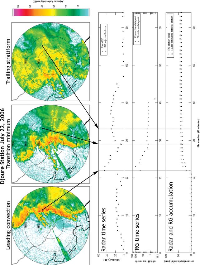
small pockets of high reflectivity (>50 dBZ). These long ing a Ze –R relationship. Figure 5 illustrates why this
radials of low stratiform reflectivity originating behind the strategy was workable only for the stratiform rainfall.
most intense leading convective cells are useful indicators Shown here is the characterization of each such radial
of whether reflectivities through long paths of widely var- (considering every 10-minute interval of the storm that
ied reflectivity are being over- or under-corrected. Thus the low-level sweep crosses a rain-gauge location) in
it was concluded that the Bénichou (1995) method was one squall line storm (22 July 2006) as a combination
over-correcting for high values, and the Battan (1973) of the estimated attenuation along the radial from radar
method was both over-correcting for low to moderate to gauge and the adjusted reflectivity in the range bin
reflectivity values, and under-correcting for high reflec- directly over the gauge. The points are further distin-
tivity values. guished as ‘convective’ (left plot) and ‘stratiform’ (right
To overcome this problem, a reflectivity–attenuation plot) following the rules noted earlier. All storm days
relationship close to Bénichou (1995), but providing for exhibited similar behaviour to that shown in Figure 5.
less attenuation at high reflectivity paths (>50 dBZ), and Note that the great majority of stratiform ray paths are
more attenuation at low to moderate reflectivity paths, characterized by path loss less than 1 dB. Even though
was applied to the data. It was observed that this rela- the stratiform region is large, the reflectivity there tends
tionship did not cause the instabilities seen using the two to be modest and so the corresponding attenuation, fol-
previous methods, but was still not adequately correcting lowing the procedure described earlier, is also modest.
for attenuation in very high reflectivity (>50 dBZ). Substantially larger path attenuations, up to 10 dB or
With the proper balance established between attenua- more, are experienced in the convective regime, and the
tion through high and low reflectivities, the prefactor of larger attenuations are particularly conspicuous for reflec-
the relationship was then increased in small increments tivities >40 dBZ. The impact of these large attenuations
(∼10%) until under-corrected attenuation in large strati- will be apparent when the radar/gauge comparisons are
form regions behind convective cells >50 dBZ was no discussed in section 4, but the main result is that attenu-
longer obvious and calculations for all paths in the dataset ation needed to be considered toward achieving accurate
Copyright
c 2010 Royal Meteorological Society Q. J. R. Meteorol. Soc. 136(s1): 289–303 (2010)RADAR/RAIN-GAUGE COMPARISONS ON SQUALL LINES 295
Figure 5. Characterization of radar-to-gauge paths for all sample pairs in the storm on 22 July 2006 based on radar scans at 0.57◦ elevation angle.
The attenuation-corrected reflectivity value over each gauge is paired with the attenuation correction along this path. Paths in the convective
regime are on the left and paths in the stratiform regime are on the right.
comparisons between radar and gauges for the convec- the error-free independent variable. Alternatively, one
tive phase. This procedure not only gives a more accurate can treat both variables symmetrically, in a so-called
reflectivity value Ze to compare with a rain-gauge read- total least squares (Nievergelt, 1994) and minimize the
ing, but it often provided a 2- to 5-fold increase in the sums of the squares of the deviations perpendicular
number of convective data pairs for deriving a Ze –R rela- to the line of best fit. The recognition of the general
tion compared with the same process without adjusting problem of representativeness in this kind of comparison
reflectivities for path attenuation is tantamount to assigning errors to both variables. All
power-law fitting in this paper makes use of the total
least squares approach to calculate a Ze –R power-law
3.4. Exclusion of reflectivity measurements with rain on
exponent (bconvective , bstratiform ). The prefactors of the
the radome
Ze –R power laws are then calculated using the following
One of the most debilitating forms of attenuation for equations to assure unbiased rainfall totals (section 3.7):
a C-band radar comes from heavy precipitation falling
Ze Ze
directly on the radome itself. In dry conditions, we expect Aconvective = bconvective , Astratiform = bstratiform ,
the radome attenuation to be a fraction of 1 dB, but during R convective R stratiform
heavy rainfall events, the layer of water running down The Ze –R relationships used for this analysis can then
the sides of the radome could be a millimetre or more be calculated using the following equations:
thick. This greatly attenuates all radar observation made
during this condition. To exclude measurements made
under these conditions from the calculation of Ze –R Zeconvective = Aconvective R bconvective ,
relationships, an average of the reflectivity value of the
Zestratiform = Astratiform R bstratiform .
first gate in each ray (all radar data within a 1 km radius)
is calculated for each 10-minute data sample. When this A is typically only slightly different than the prefactor
average value exceeds 36 dBZ (a value observed to be a calculated using the total least squares approach, but
clear indicator of overhead convection), the correspond- serves to provide unbiased rainfall totals using the
ing data time is excluded from the Ze –R calculation. following equation for integrated bias (Steiner et al.,
Typically, this ‘dead’ period amounts to 10–20% of the 1999), where Ri is the total:
radar/gauge data processing period for a given storm.
n
Ri
3.5. General regression methods i=1
B= .
n
In arriving at power-law fits in Ze –R plots generated Gi
i=1
in this study, one is faced with three options. One
can regress reflectivity Z against R, with R the error- In this equation, Ri is the total rainfall estimated for a
free independent variable (the traditional approach in gauge by the radar for an entire event, and Gi is the total
radar meteorology), or regress R against Z, with Z rainfall measured by said gauge for the entire event.
Copyright
c 2010 Royal Meteorological Society Q. J. R. Meteorol. Soc. 136(s1): 289–303 (2010)296 B. RUSSELL ET AL.
3.6. Development of Ze –R scatter plots Two measures of success were computed for each
of these plots: the mean accuracy between radar and
Scatter plots of radar-measured Ze versus gauge– gauge (‘Error’ below), and the mean absolute value of the
measured R were prepared at the finest time resolution accuracy of each gauge (e.g. Smith and Krajewski, 1991;
of the radar samples – 10 minutes. In such plots that Steiner et al., 1999) between radar and gauge (‘|Error|’
included all data pairs, the conspicuous presence of out- below). These quantities are defined as follows:
lier points was predominantly (though not exclusively)
an indication that the radar estimates of rainfall were Error = 1 Ri − Gi 1 Ri − Gi
n n
|Error| = | |
low in comparison to the gauges. These outlier points n Gi n Gi
i=1 i=1
were notably more frequent in the convective regime
than the stratiform regime. These points were tenta-
tively attributed to the presence of reflectivity gradients where Ri and Gi are the rainfall determinations by radar
and heterogeneously populated pulse resolution volumes and gauge, respectively.
(Rogers, 1971; Rosenfeld et al., 1992), and in many cases
this assumption was later confirmed by the detailed exam-
ination of outlier points in both the radar observations 4. Results
(full scan analysis) and rain-gauge records. A filter was The procedures discussed in the foregoing section 3
developed to eliminate these extreme outliers from the have been applied to squall line storms in 2006 and
Ze –R fits. 2007. Separate Ze –R scatter plots, total least-squares fits,
For every reflectivity–rainfall rate data pair considered and radar/rain-gauge comparisons are produced for each
for inclusion in the Ze –R calculation, the change in rain- day, for both the convective and stratiform regimes. A
fall rate measured by the rain-gauge since the previous summary of all the days examined is shown in Table II.
data pair (10 minutes ago) was calculated by first con- Three individual days, one from each month in 2006
verting the two rainfall rates to dBZ equivalents using the (22 July, 18 August and 8 September) have been selected
Z –R relationship of Z = 239R 1.45 derived by Chamsi for more detailed illustration, and are all included in
(1992) based on disdrometer measurements made earlier Figure 6. These cases tend to be the stronger, longer-
in Niamey in the convective phase. Points with a jump or lived squall lines, but serve to represent both the suc-
drop of more than 10 dBZ in 10 minutes were classified cesses and limitations of our approach. Figure 6 shows
as gradient-region points, and not included in the final the Ze –R scatter plots for the convective and stratiform
Z –R calculation. In many cases these were clear outliers periods (two left-hand panels), and the radar/gauge com-
in the unfiltered Ze –R diagram. Following the rejection parisons for storm-integrated rainfall for the convective
of the ‘gradient’ points, a total least squares fit was per- (third panels) and stratiform (right-hand panels) regimes.
formed on the remaining points for the convective and The individual points in the Ze –R scatter plots represent
stratiform regions independently to determine power-law radar/gauge pairs at 10-minute resolution. The scatter is
relations between Ze and R. manageable and the correlation coefficients (with num-
To assure a strong signal-to-noise ratio on the radar bers of points in the fits in the range ∼150–300, owing
measurements, all values less than 20 dBZ were excluded in large part to the large number of rain-gauges available),
2
from the comparisons, for both the convective and the r values for best fit are in the range 0.70 to 0.85. The
stratiform fits. For typical Z –R relations (summarized power-law fits tend to follow the trends observed in Z –R
in Table III) this 20 dBZ cut-off is equivalent to about fits based on disdrometer measurements, to the extent that
0.5 mm/h of rainfall rate, a modest level even in stratiform the prefactor in the power law for the stratiform regime
rain. It is also customary in published disdrometer results is larger than that for the convective regime. At the same
to exclude the values in very light rain, and one should time, both prefactors extracted by these methods tend to
also keep in mind that the lower the rain rate the less be low (by a factor of ∼2, or 3 dB relative to typical
reliable the rain estimation from tipping-bucket gauges disdrometer analyses of power-law fits on Z –R scatter
for 5-minute time steps. plots, see also Table III).
When the radar/gauge comparisons are considered (two
right-hand panels), it is clear that the stratiform cases
3.7. Radar–gauge comparisons for storm totals for all days show a tighter grouping of points and
a greater accuracy. Each plotted point represents the
To assess the accuracy with which the single power- comparison at a specific rain-gauge for the accumulated
law relationships developed from the Ze –R fits could rainfall for the entire storm. The convective cases show
work for the entire collection of rain-gauges, comparisons considerably greater scatter around the diagonal line of
were made between radar and gauge for the entire gauge perfect agreement. It is important to note that a systematic
accumulation for individual storms. This test provided bias (radar reading low) was present in earlier calculations
some measure of how well one could determine rainfall (not shown) for which attenuation corrections along the
over an area substantially larger than that covered by the ray paths to gauges were not implemented.
gauge network on the basis of the radar measurements The radar/gauge comparisons for all convective
alone. In these plots, the diagonal line represents perfect regimes in all storms showed pronounced outlier points in
agreement between gauge (abscissa) and radar (ordinate). the radar/gauge comparison plots, and considerable atten-
Copyright
c 2010 Royal Meteorological Society Q. J. R. Meteorol. Soc. 136(s1): 289–303 (2010)Copyright
Table II. Ze –R relationships for convective and stratiform regimes for selected Niamey squall lines from 2006 and 2007. Values for rainfall accuracy are also shown.
Date 1 2 3 4 5 6 7 8 9 10 11 12 13 14
14/07/2006 186 1.35 0.806 191 37 16% 53% 299 1.46 0.620 172 10 −10% 36%
19/07/2006 56 1.71 0.804 152 27 15% 46% 305 1.24 0.763 314 10 14% 47%
22/07/2006 96 1.32 0.705 162 44 29% 59% 278 1.24 0.589 250 3 23% 52%
31/07/2006 471 0.98 0.844 110 31 20% 52% 272 1.73 0.681 92 7 −9% 36%
03/08/2006 109 1.47 0.804 122 36 11% 45% 171 1.80 0.672 52 5 25% 48%
c 2010 Royal Meteorological Society
06/08/2006 67 1.51 0.806 357 53 15% 35% 219 1.05 0.737 274 4 16% 36%
18/08/2006 63 1.46 0.851 150 35 0.9% 35% 181 1.49 0.709 208 4 1% 36%
08/09/2006 143 1.36 0.760 209 38 9.1% 45% 256 1.22 0.765 295 11 9% 45%
24/09/2006 85 1.37 0.729 149 12 21% 51% 228 1.28 0.599 568 15 22% 52%
22/07/2007 234 1.07 0.756 286 52 45% 87% 212 1.33 0.566 494 32 26% 76%
02/08/2007 21 1.73 0.710 169 23 15% 36% 165 0.97 0.705 277 10 15% 38%
14/08/2007 125 1.30 0.751 284 44 2.5% 35% 221 1.47 0.649 429 37 0.4% 35%
14/09/2007 263 1.21 0.775 55 21 46% 84% 330 1.00 0.541 64 3 21% 43%
1 Convective Z e –R prefactor
2 Convective Z e –R exponent
3 Convective Z e –R correlation coefficient (r2)
4 Total points used in convective Z e –R calculation
5 Total points filtered from convective Z e –R calculation
6 Mean convective accuracy
7 Mean magnitude of convective accuracy
8 Stratiform Z e –R prefactor
9 Stratiform Z e –R exponent
RADAR/RAIN-GAUGE COMPARISONS ON SQUALL LINES
10 Stratiform Z e –R correlation (r2)
11 Total points used in stratiform Z e –R calculation
12 Total points filtered from stratiform Z e –R calculation
13 Mean stratiform accuracy
14 Mean magnitude of stratiform accuracy
Q. J. R. Meteorol. Soc. 136(s1): 289–303 (2010)
297298 B. RUSSELL ET AL.
tion was devoted to scrutinizing these cases. It is clearly (2) Radar measurement occurs through a long path
visible from examining the accumulation plots for the (10–20 km) of high reflectivity (dBZ > 50). This
convective and stratiform regions in Figure 6 that there leads to a positively biased outlier
is much more scatter in the convective regime than the
stratiform regime. This is expected since the stratiform The outliers in the convective regimes in Figure 6 are
regime is generally free of the large reflectivity gradients all examples of these phenomena, with more than 90% of
found in the convective regime. Examination of the data them being caused by measurements made in regions of
time series containing large, positive outliers showed that large spatial gradients, or at times during large temporal
they originate from data samples when the rain-gauge gradients in rainfall (cause (1) above).
was on the outer edge of a small pocket of very high
reflectivity(>60 dBZ). The outliers with very large bias
from 22 July 2006 in Figure 6 are good examples of 5. Discussion
this phenomenon. Examination of the 5-minute rainfall The abundance of squall lines during the AMMA cam-
rates used in those cases often showed a pair of one paign, underlain by more than fifty rain-gauges (Figure 1),
relatively low rainfall rate, and one very high rainfall rate has enabled a good characterization of Ze –R power laws
(>100 mm/h). Outliers with large negative bias originate for the convective and stratiform regions of individual
from large path attenuation, either a long path through storms. The challenging aspect here is that C-band atten-
moderate reflectivity, or a path passing through a very uation, substantial reflectivity/rainfall gradients and the
high reflectivity (>60 dBZ). general radar representativeness of the ‘point’ rain-gauge
In general, the stratiform region exhibits many fewer measurement must all be contended with in interpreting
outliers than the convective, and is much more tightly the results. (Despite the large number of gauges, the mean
clustered. The few outliers that do occur are attributed distance between gauges in the AMMA network is of the
to data points being incorrectly classed as stratiform order of a thunderstorm diameter, and perhaps an order
when in fact they are convective data. The algorithm of magnitude greater than the size of strong precipitation
used to classify these points works well, but is not 100% shafts in the cores of the storms.) Because the attenua-
accurate. The fact that outliers in the stratiform regime tion and sampling factors in the radar measurements are
tend to be negative instead of positive supports the idea often superimposed, it is not always possible to identify
that positive outliers originate from gradient regions, uniquely the origins of specific discrepancies.
and negative outliers tend to come from insufficient The attenuation problem has been successfully treated
adjustment of path attenuation. by an iterative approach, and the treatment of attenua-
The conspicuous outliers in the Ze –R scatter plots tion ‘shadows’ cast on the stratiform region by strong
came from measurements in regions with reflectivity convective cells in the leading line lends considerable
gradients, and thus were excluded from the evaluations confidence to earlier estimates by Battan (1973) and
for best fit. These points represent more often than not Bénichou (1995), though a slightly improved relationship
a low reading of the radar relative to the gauge, and we was derived here. It was found necessary to correct all
have no easy means to correct the Z values. If these ‘bad’ reflectivity measurements over gauges, both to assure an
points are left in the radar/gauge comparison plots, then adequate number of data points for the regressions, but
they result in anomalously large rainfall estimates. also to assure more accurate radar rainfall estimates in
After analysing the outliers from the convective events, the radar/gauge comparisons.
it is clear that the discrepancy in rainfall between the The expectation discussed in the Introduction for an
radar estimate and gauge measurement for these points approximate matching of fits for disdrometer comparisons
originates from one or two data points in the time series and for the Ze –R scatter plots is not upheld in this study.
of that gauge. The data pairs causing these errors always A comparison of power-law relations from the literature
involve one or the other of the following: is shown in Table III. Comparison with the Ze –R fits in
Table II show a clear tendency for the prefactors produced
here to be low. To be more quantitative here, we have
(1) Radar measurement coincides with a large gradient computed the mean power-law prefactors for the Ze –R
in rainfall directly over the gauge. This circum- relations for 13 cases in Table II with the mean prefactors
stance results in one of two things: for the Z –R power-law relations in Table III. The result
is 3.0 dB for the convective regions and 1.5 dB for the
• The rain-gauge is recording extremely high stratiform regions, with the Ze –R on the prefactor low
rainfall rate (100–200 mm/h and higher), and side in both cases. The explanation for this discrepancy
the radar reads a relatively low reflectivity. is not well understood at present. Evidence that the radar
This leads to a positively biased outlier. is absolutely calibrated at the 1 dB level is presented in
• The rain-gauge is recording relatively low the Appendix, yet the Ze –R prefactors are low relative
rainfall rate and the radar reads high reflec- to traditional Z –R fits, even ones made earlier with
tivity (small cells of high reflectivity within disdrometers in Niamey, Niger. Evidence has been found
the PRV but missed by the rain-gauge). This more recently (through comparisons of reflectivity at two
causes a negatively biased outlier. tilts over the same gauges) that the use of the lowest beam
Copyright
c 2010 Royal Meteorological Society Q. J. R. Meteorol. Soc. 136(s1): 289–303 (2010)RADAR/RAIN-GAUGE COMPARISONS ON SQUALL LINES 299
Table III. Summary of disdrometer Z –R relationships from the literature.
Convective Z-R Stratiform Z-R Investigator Measurement location
Z = 139R 1.43
Z = 367R 1.3
Tokay and Short (1996) Kapingamarangi Atoll, Pacific Ocean
Z = 766R 1.14 Z = 233R 1.01 Atlas et al. (1999) Kapingamarangi Atoll. Pacific Ocean
Z = 99R 1.47 Z = 252R 1.61
Z = 588R 1.08 Z = 88.7R 1.9
Z = 334R 1.19 Z = 278R 1.44
Z = 233R 1.39 Z = 532R 1.28 Maki et al. (2001) Darwin, Australia
Z = 315R 1.38 Z = 463R 1.4 Uijlenhoet et al. (2003) Mississippi, USA
Z = 205R 1.43 Z = 405R 1.28 Nzeukou et al. (2004) Senegal
Z = 144R 1.51 Z = 351R 1.24
Z = 146R 1.53 Z = 387R 1.25
Z = 153R 1.46 Z = 352R 1.22
Z = 162R 1.48 Z = 385R 1.21 Nzeukou et al. (2004) Senegal
Z = 289R 1.43 Z = 562R 1.44 Moumouni et al. (2008) Benin
Z = 343R 1.38 Z = 468R 0.9 Top Z-R: squall lines only
Bottom Z-R: all types of system
Figure 6. Ze –R scatter diagrams for selected storms for convective and stratiform regimes (left-hand column), radar/gauge comparisons for
convective storm totals (centre column), and radar/gauge comparisons for stratiform storm totals (right-hand column).
tilt (0.57◦ ) in all of the gauge comparisons may be causing read low relative to the radar measurement of reflectivity
a 1–2 dB degradation in the reflectivity estimates for the at higher altitude. We have also thought earlier that a
radar, and this may account for part of the discrepancy larger C-band attenuation, such as that found by Atlas
here. This discrepancy does not find an explanation in the et al. (1993) in Darwin, Australia, could possibly account
evaporation of rain or raindrop break-up in the boundary for the prefactor discrepancy, but as noted earlier, the
layer, both of which would tend to cause the gauges to attenuation was checked carefully here and found to be
Copyright
c 2010 Royal Meteorological Society Q. J. R. Meteorol. Soc. 136(s1): 289–303 (2010)300 B. RUSSELL ET AL.
broadly consistent with the more modest levels reported storms, was made for both a physical reason and a
in the literature (Battan, 1973; Bénichou, 1995). Recent practical one. The practical choice enables a clear-cut
measurements by Rickenbach et al. (2009), also making separation of convective and stratiform for subsequent
use of MIT radar data in Niger in the AMMA context (see digital analysis.
Appendix), indicate agreement in absolute calibration at
the 1 dB level for the majority of the pixel comparisons
with the NASA TRMM radar in space, but the difference 6. Conclusions
histogram is skewed toward positive differences, with the
The main results of this study can be summarized as
MIT radar reading low by a mean of ∼1–2 dB These
follows:
results by themselves do not account for the prefactor
discrepancy, but together with the beam loss effect, may (1) Ze –R power-law fits have been determined for the
explain the observed differences. convective and stratiform regions of squall lines
The existence of pronounced negative deviations (out- in West Africa on a number of days. Methods
liers) in the Ze –R plots which were clearly associated for bias adjustment have been successfully imple-
with either pronounced temporal changes in the gauge mented. Considerably variability is noted case-to-
observations, or with spatial gradients in the PPI scans case, consistent with drop size measurements dur-
in the vicinity of the gauge, have been associated with ing AMMA. These relationships enable radar eval-
the systematic errors predicted for non-uniformly popu- uations of rainfall and attendant latent heat release
lated pulse resolution volumes and logarithmic receivers over areas substantially larger than covered by the
(Rogers, 1971). These sometimes notable outliers were gauges.
removed from the Ze –R scatter plots prior to fitting. Such (2) Comparisons of radar and gauge measurements of
effects are difficult if not impossible to correct for because storm total rainfall show substantially better agree-
one lacks detailed information on gradient structure. In ment for the stratiform regime than the convective
other circumstances, the radar was found to be reading regime.
low when rain-gushes of order 100 mm/h gauge rates (3) Correction for attenuation at C-band is essential
were observed for some of these outliers, or a temporal for satisfactory results. Workable iterative methods
aliasing problem was evident, with the rain arriving at a have been developed to implement these correc-
gauge near the middle of the 10-minute interval between tions.
radar sweeps over that gauge. The only way to remedy (4) The prefactors in the Ze –R power-law fits
the loss of such events to the accumulated rainfall is to (Table II) are systematically smaller than prefac-
sacrifice on volume scans, and increase the repetition fre- tors for published Z –R fits on disdrometer data
quency of the low-level radar sweeps. Such a procedure (Table III). The reasons for this discrepancy are
was not undertaken during AMMA because of the interest tentatively attributed to partial loss of beam energy
in the vertical development of the convection. in the use of the lowest radar tilt (0.57◦ , less than
The most notable contrast between convective and half the 3 dB beam width), and to the radar reading
stratiform regimes in the analysis considered here was 1–2 dB low (based on the TRMM comparisons).
found in the radar/gauge comparison plots. The substan- This discrepancy fortunately does not impair the
tially tighter behaviour of the stratiform regime on all rainfall estimates using the radar data, and in this
days examined is attributed to the greater spatial unifor- context it is important to emphasize that future
mity and more modest reflectivity of the stratiform region users of the MIT radar data for quantitative rain-
that served to suppress gradient effects and which also fall estimates are advised to use the Ze –R relations
required substantially smaller attenuation correction (Fig-
for specific days of interest in Table II, and also to
ure 5). Another intriguing question raised by this study
make use of reflectivity measurements at the low-
pertains to what physical processes are causing such large
est elevation angle (0.57◦ ) from which the Ze –R
variance in Ze –R relationship values from storm to storm
relations were derived.
(Table II).
(5) The Ze –R relationships derived here are limited
Some guidance is in order for the use of these
in application to MIT radar data from its operation
results in producing quantitative rainfall estimates for
in 2006 and 2007, and should not be applied to
the convective and stratiform regimes of the squall lines
reflectivity data from other AMMA radars such as
investigated. First of all, the reflectivity data need to
those in Benin.
be corrected for attenuation following the procedure
in section 3.3 before the Ze –R relation is applied.
The regime definition here is based on the analyses
Acknowledgements
of individual reflectivity time series over individual
gauges (Figures 2 and 3). It is not recommended that Discussions with D. Rosenfeld, D. Atlas, C. Ulbrich,
the same procedure be followed in transforming the R. Cifeli and S. Rutledge on the treatment of C-band
substantially larger field of radar reflectivity at all other attenuation are appreciated. R. Boldi provided important
locations to rainfall or latent heating. The choice of assistance on the different approaches to least-squares fit-
minimum reflectivity in the transition region, a location ting. Discussions of a more general nature on radar/gauge
usually clearly identified in individual PPI scans of these comparisons with D. Atlas, P.Austin, S.Geotis (deceased),
Copyright
c 2010 Royal Meteorological Society Q. J. R. Meteorol. Soc. 136(s1): 289–303 (2010)RADAR/RAIN-GAUGE COMPARISONS ON SQUALL LINES 301
R. Lhermitte, D. Rosenfeld, H. Sauvageot, M. Steiner and Values for the relevant radar parameters are given
I. Zawadzki are also acknowledged. Eyal Amitai provided below.
valuable advice on the calculation of bias-free Ze –R rela-
tionships. The ARM team in Niamey (K. Nitschke and λ = 5.37 cm
M. Alsop) provided helium and balloons for sphere cal- 2πr/λ = 8.9 (7.6 cm diameter sphere)
ibrations in Niamey. J. Lutz, A. Siggia, J. Seltzer, S. 2πr/λ = 17.8 (15.2 cm diameter sphere)
Copeland and the late M. Couture prepared the radar
h = 300 m (1 µs pulse length)
for shipment and installation in Africa. S. Salou, M.
Abdoulaye and C. Owbandowaki hosted the radar oper- ϕ = 1.62◦ = 0.0283 rad
ation at l’Armée de l’Air, the Niger Air Force Base. θ = 1.52◦ = 0.0265 rad
Support for the radar operation in Africa came from
NASA Hydrology (Jared Entin) and from RIPIECSA Equating expressions (A1) and (A2), with the use of
(Arona Diedhiou). Chris Thorncroft provided enthusias- (A3) and the values for the radar parameters, enables a
tic support for the radar funding. We also thank the many determination of the radar reflectivity Z (in conventional
AMMA and RIPIECSA participants for their contribu- units for reflectivity, mm6 /m3 ) expected from the full
tion in the round-the-clock operation of the radar for radar equation for a calibration sphere at an arbitrary radar
two wet seasons. E.R. Williams and B. Russell were sup- range R, and yields the prediction
ported in this study by a grant from the Climate Dynamics
Program of the US National Science Foundation (ATM Z = 105 r 2 /R2 mm6 /m3 (A4)
0734806).
with sphere radius r in centimetres and radar range R in
kilometres.
Appendix
A2. Radar Measurements on Tethered Metal Spheres
Calibration of Mit Radar with Metal Spheres
Calibration measurements on metal spheres raised with
A1. Theoretical Basis tethered hydrogen-filled neoprene balloons, at heights
of several hundred metres, were attempted on multiple
The radar is absolutely calibrated with a metal sphere occasions in both the 2006 and 2007 field campaigns in
whose radar cross-section (σ with units m2 ) is accurately Niamey.
known. The dimensionless scattering parameter for a The absolute pointing of the radar antenna had been
sphere of radius r is 2πr/λ, and when this number is reliably established earlier in each field campaign with
large, the cross section σ becomes the geometrical cross- Sun-tracking procedures enabled by SIGMET radar
section of the sphere, πr 2 . The calibration sphere is a software. For each sphere calibration measurement, a
point target for the radar, unlike the volume target η (with theodolite was set up on the radar tower directly beneath
units m2 /m3 ) of raindrops whose accurate reflectivity Z the antenna, and was used in manual mode throughout
is desired for the measurement of rainfall. For a volume the measurements to establish the azimuth and elevation
target whose spherical scatterers conform to the Rayleigh angles of the calibration sphere to aid in the pointing
regime (diameter D small in comparison to a wavelength of the radar antenna, and the maximization of the radar
λ), the volume reflectivity η is given by (Battan, 1973; return.
equation 4.24): The most successful radar calibration was performed
on 22 September 2007, when measurements were made
π 5 |k|5 Z on both 6 diameter (r = 7.62 cm) and 12 diameter (r =
η= m2 /m3 (A1) 15.2 cm) aluminium calibration spheres (manufactured
λ4 by Carlstrom Pressed Metals, Worcester, Massachusetts).
The best estimate of the radar range R is 2.97 km. A
It is convenient to form a range-dependent volume target
comparison of predictions based on equation (4) with
for the calibration sphere, given simply by
the radar measurements using the SIGMET A-Scope
program, in which the range-normalized return from the
η = σ/P RV m2 /m3 (A2) metal sphere target is given in dBZ units, are shown
below
where PRV is the range-dependent pulse resolution
volume, given by (Battan, 1973; equation 4.7) Predicted Measured
6 sphere 28.4 dBZ 28.3 +/− 0.5 dBZ
12 sphere 34.4 dBZ 35.5 +/− 0.5 dBZ
P RV = π θ ϕ h/8 m3 (A3)
Agreement between theory and measurement on the 6
in which ϕ is the horizontal (3 dB) beamwidth of the sphere is excellent. For reasons we do not understand,
radar antenna, θ is the vertical beamwidth, and h is the the clean 6 dB difference in radar cross-section expected
radar pulse length. for 6 and 12 spheres was not exactly realized, and the
Copyright
c 2010 Royal Meteorological Society Q. J. R. Meteorol. Soc. 136(s1): 289–303 (2010)302 B. RUSSELL ET AL.
Battan LJ. 1973. Radar observation of the atmosphere. University of
Chicago Press.
Bénichou H. 1995. ‘Utilisation d’un radar météorologique bande
C pour la mesure des pluies au Sahel: Étude du phénomène
d’atténuation’. Univ. J. Fourier: Grenoble.
Calheiros RV, Zawadzki II. 1987. Reflectivity-rain rate relationships
for radar hydrology in Brazil. J. Clim. Appl. Meteorol. 26:
118–132.
Chamsi N. 1992. ‘Estimation des précipitations à partir de la
réflectivité radar dans les systèmes convectifs tropicaux ’. Doctoral
thesis, Université Paul Sabatier, Toulouse, France, 110 pp.
Delrieu G, Hucke L, Creutin JD. 1999. Attenuation in rain for X- and
C-band weather radar systems: Sensitivity with respect to the drop
size distribution. J. Appl. Meteorol. 38: 57–68.
Engholm CD, Williams ER, Dole RM. 1990. Meteorological and
electrical conditions associated with positive cloud-to-ground
lightning. Mon. Weather Rev. 118: 470–487.
Geotis SG. 1975. ‘Some measurements of the attenuation of 5-
cm radiation in rain’. Pp 63–66 in Preprints, 16 th Conf. on
Radar Meteorology, Houston, Texas, 22–24 April 1975. American
Meteorological Society.
Hildebrand PH. 1978. Iterative correction for attenuation of 5 cm radar
in rain. J. Appl. Meteorol. 17: 508–514.
Hitschfeld W, Bordan J. 1954. Errors inherent in the radar measurement
of rainfall at attenuating wavelengths. J. Meteorol. 11: 58–67.
Le Barbé L, Lebel T. 1997. Rainfall climatology of the HAPEX-
Figure A1. Histogram comparison of point comparisons of TRMM Sahel region during years 1950–1990. J. Hydrol. 188–189:
precipitation radar in space and the MIT radar in Niamey, Niger for 46–73.
ground-based observations in the lowest radar tilt (0.57◦ ). Maki M, Keenan TD, Sasaki Y, Nakamura K. 2001. Characteristics
of the raindrop size distribution in tropical continental squall
lines observed in Darwin, Australia. J. Appl. Meteorol. 40:
larger sphere was systematically larger than expected. 1393–1412.
Nevertheless, the measured cross-section for the larger Moumouni S, Gosset M, Houngninou E. 2008. Main features of
rain drop size distributions observed in Benin, West Africa,
sphere is still within 1.1 dB of the prediction, about as with optical disdrometers. Geophys. Res. Lett. 35: L23807,
good as one can expect in typical calibration measure- DOI:10.1029/2008GL035755.
ments of this kind. Calibration measurements of a similar Nievergelt Y. 1994. Total least squares: State-of-the-art regression in
kind performed in 2006 were also found to agree at the numerical analysis. SIAM Review 36: 258–264.
Nzeukou A, Sauvageot H, Ochou AD, Kebe CMF. 2004. Raindrop size
nominal +/−1 dB level. distribution and radar parameters at Cape Verde. J. Appl. Meteorol.
An additional check on the calibration of the MIT 43: 90–105.
radar has been afforded by detailed comparisons with Rickenbach TM, Rutledge SA. 1998. Convection in TOGA COARE:
Horizontal scale, morphology, and rainfall production. J. Atmos. Sci.
the 2A25 dataset from the TRMM precipitation radar 55: 2715–2729.
in space (Rickenbach et al., 2009). These comparisons Rickenbach TM, Nieto Ferreira R, Guy N, Williams ER. 2009.
involved point-to-point comparisons between the three- Radar-observed squall line propagation and the diurnal cycle of
dimensional volume scan information from the radar convection in Niamey, Niger during the 2006 African Monsoon and
Multidisciplinary Analyses Intensive Observing Period. J. Geophys.
and the ground track data from the TRMM precipitation Res. 114: D03107, DOI:10.1029/2008JD010871.
radar. Figure A1 shows the comparisons on 14 August Rogers RR. 1971. The effect of variable target reflectivity on
2006. The most likely offset is 0 dB, but the distribution weather radar measurements. Q. J. R. Meteorol. Soc. 97:
154–167.
is noticeably skewed to positive values, with a mean Rosenfeld D, Atlas D, Wolff DB, Amitai E. 1992. Beamwidth effects
point-to point difference of 3.1 dB, suggesting that the on Z–R relations and area-integrated rainfall. J. Appl. Meteorol. 31:
radar is reading low in the upper tilts by 1–2 dB. This 454–464.
may also provide some explanation for the discrepancy Rosenfeld D, Wolff DB, Atlas D. 1993. General probability-matched
relations between radar reflectivity and rain rate. J. Appl. Meteorol.
in power-law prefactors addressed in the Discussion 32: 50–72.
section. Smith JA, Krajewski WF. 1991. Estimation of the mean
field bias of radar rainfall estimates. J. Appl. Meteorol. 30:
397–412.
References Steiner M, Smith JA, Burgess SJ, Alonso CV, Darden RW.
Ali A, Lebel T, Amani A. 2005. Rainfall estimation in the Sahel. Part 1999. Effect of bias adjustment and rain gauge data quality
I: Error function. J. Appl. Meteorol. 44: 1691–1706. control on radar rainfall estimation. Water Resour. Res. 35:
Atlas D, Rosenfeld D, Wolff DB. 1993. C-band attenuation by tropical 2487–2503.
rainfall in Darwin, Australia using climatologically tuned Ze –R Tokay A, Short DA. 1996. Evidence from tropical raindrop spectra of
relations. J. Appl. Meteorol. 32: 426–430. the origin of rain from stratiform versus convective clouds. J. Appl.
Atlas D, Ulbrich CW, Marks Jr FD, Amitai E, Williams CR. 1999. Meteorol. 35: 355–371.
Systematic variation of drop size and radar-rainfall relations. J. Uijlenhoet R, Steiner M, Smith JA. 2003. Variability of raindrop size
Geophys. Res. 104: 6155–6169. distributions in a squall line and implications for radar rainfall
Austin PM. 1987. Relation between measured radar reflectivity and estimation. J. Hydrometeorol. 4: 43–61.
surface rainfall. Mon. Weather Rev. 115: 1053–1070. Williams ER, Weber ME, Orville RE. 1989a. The relationship between
Balme M, Vischel T, Lebel T, Peugeot C, Galle S. 2006. Assessing lightning type and convective state of thunderclouds. J. Geophys.
the water balance in the Sahel: Impact of small scale rainfall Res. 94: 13213–13220.
variability on runoff. Part 1: Rainfall variability analysis. J. Hydrol. Williams ER, Geotis SG, Bhattacharya AB. 1989b. A radar study of
331: 336–348. the plasma and geometry of lightning. J. Atmos. Sci. 46: 1173–1185.
Copyright
c 2010 Royal Meteorological Society Q. J. R. Meteorol. Soc. 136(s1): 289–303 (2010)You can also read