RC8021 Indoor Camera - Installation Guide
←
→
Page content transcription
If your browser does not render page correctly, please read the page content below
RC8021
              Indoor Camera

          Installation Guide
P/N: 957YL502GJ Document Version: 1.0
Copyright 2011. All Rights Reserved.
All trademarks and trade names are the properties of their respective
owners

                                   i
Package Contents
The following items should be included: If any of these items are
damaged or missing, please contact your service provider immediately.

1.   Indoor Camera

2.   Antenna

3.   6 feet long Power Adapter

4.   Camera Stand

5.   Mounting Screw

6.   Ethernet Cable

                                 ii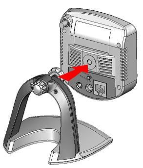
1
Chapter 1
Introduction
This Chapter provides details of the Indoor Camera's
features, components and capabilities.
Overview
The Indoor Camera has an Integrated Microcomputer and a high quality
digital-Image-Sensor, enabling it to display high quality live streaming
video.
Features
Standalone Design: The Indoor Camera is a standalone system
with a built-in CPU and Video encoder. It requires only a power
source and a connection to your Router.
Dual Video Support: The Indoor Camera can support both MPEG4
and MJPEG video for different image compression.
Wired and Wireless Network Support: The Indoor Camera
supports either wired or wireless transmission.
Motion Detection: The Indoor Camera can detect motion in its field
of view. Motion detection is achieved by comparing consecutive
frames to detect movement of large objects. This function only
works indoors due to the sensitivity of the sensor. When motion is
detected, an alert can be sent, or some other action may be
triggered.
Wireless Features
Standards Compliant: The Indoor Camera complies with the
IEEE802.11g (DSSS) specifications for Wireless LANs.
Supports both 802.11b and 802.11g Standards: The Indoor
Camera supports both 802.11b and 802.11g standards.
Speeds up to 54Mbps: All speeds up to the 802.11g maximum of
54Mbps are supported.
Security Support: Full WEP (64/128 Bit), WPA and WPA2
Personal standards are supported on the Wireless interface,
allowing advanced encryption of wireless data.
1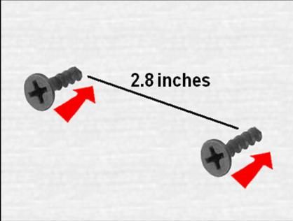
2
Chapter 2
Basic Setup
This Chapter provides details on how to setup and mount
the Indoor Camera.
System Requirements
To use the Wired Interface, a standard router and network cable are
required.
To use the Wireless interface, other Wireless devices must be
compliant with the IEEE802.11b or IEEE802.11g specifications. All
Wireless stations must use compatible settings.
Physical Details – Indoor Camera
Front Panel - Indoor Camera
Figure 1: Front Panel – Indoor Camera
1. Lens No physical adjustment is required or possible for
the lens, but you should ensure that the lens cover
remains clean. Image quality is degraded if the lens
cover is dirty or smudged.
2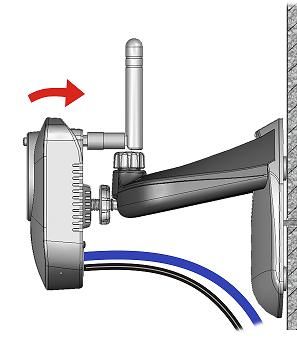
2. Microphone      The Indoor Camera comes with a built-in
                   microphone.
  (Not currently
  supported)
3. Power LED       On - Powered on
                   Off - No power
                   Blinking - The Power LED blinks during start up.
                   This can take up to 20 seconds
4. Reset           The reset button is located at the bottom of the
   Button          indoor camera. This button is recessed; a pin or a
                   paper clip can be used to push it. It can be
                   activated at any time when the camera is powered
                   on.
                   Reset to default manufacturer values and
                   reboot: When pressed and held for over 10
                   seconds, settings of the Indoor Camera will be set
                   to their default manufacturer values.
                   Note: After this procedure is completed, the Power
                   LED will blink three times to confirm that the reset
                   was successfully completed.
5. Privacy         When the privacy feature is enabled, live video
   Button          cannot be accessed.
                   On (Green) - The privacy feature is activated
                   Off - The privacy feature is not in use
6. Network         The Network LED displays the current status of the
   LED             Indoor Camera’s connection to the Network via
                   either the Wired or Wireless interface.
                   On (Green) – Indoor camera is connected to
                   network.
                   Off – Indoor Camera is not connected to the
                   Network
                   Blinking (Green) - Data is being transmitted.
                   On (Amber) - If the LED is on for 5 seconds, the
                   WPS is not processing successfully
                   Blinking (Amber) - WPS function is being
                   processed successfully.

                                    3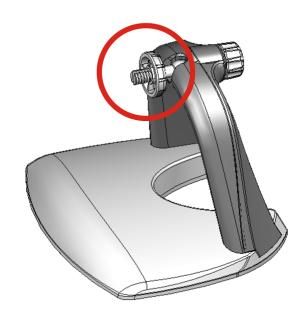
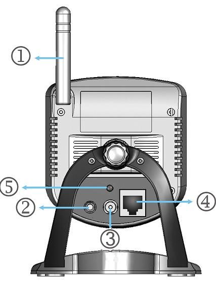
Rear Panel - Indoor Camera

                 Figure 2: Rear Panel – Indoor Camera

1. Antenna       The antenna is adjustable; best results are usually
                 obtained with the antenna positioned vertically.
2. Speaker Out An external speaker can be plugged in here.
   (Not currently
   supported)
3. Power Port    The supplied 5V power adapter plugs in here to
                 power on the Indoor Camera.
                 Note: Do not use any other power adapters since
                       doing so may damage the Indoor Camera.

                                  4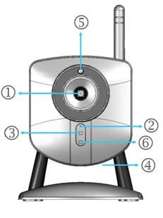
4. Ethernet The supplied Ethernet cable plugs in here enabling
Port you to connect your Indoor Camera to your router.
Note:
Plugging in the Ethernet cable will disable the
Wireless interface. Only one (1) interface can be
active at any time.
The Ethernet cable should only be connected or
disconnected when the camera is powered
OFF. Attaching or detaching the Ethernet cable
while the camera is powered on does NOT
switch the interface between wired and wireless.
Detaching the Ethernet cable when the camera
is powered ON will disconnect the indoor
camera from the network.
5. WPS Button The WPS feature when used with other WPS
(Not currently enabled wireless devices automatically creates an
supported) encryption-secured wireless connection. The
gateway is not enabled for WPS connectivity.
Setup the Indoor Camera
Please follow the steps below to assemble and connect your camera.
Once complete, you have the option to utilize your camera in a wired or
wireless fashion.
Go to http://monitoringcontrol.verizon.com and follow the steps provided
in the online setup wizard. This will enable you to setup and connect
your camera to the Home Control Network.
You may also follow the steps below to assemble your camera and then
visit the online setup wizard to connect your camera.
Connect the Indoor Camera’s Stand
Step 1: Connect the Indoor Camera’s Stand
a. Hold the metal screw up.
5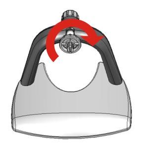
b. On the back of the stand, turn the plastic knob clockwise to
     tighten the metal screw into position.

  c. Face the back of the indoor camera to the stand and turn the
     Indoor Camera clockwise to attach it to the stand.

Step 2: Attach the Antenna
  a. Attach the antenna to the Indoor Camera by turning it clockwise
     onto the back of the camera.
  b. Put the antenna in the upright position to improve wireless
     reception.

                                  6
Step 3: Visit the Online Portal
Go to http://monitoringcontrol.verizon.com and follow the steps provided
in the online setup wizard. This will enable you to setup and connect
your camera to the Home Control Network.
*Optional: Mount the Indoor Camera
*Note: The Indoor Camera can also be placed on a table using the
stand provided.
Note: Please ensure the Indoor Camera is configured and added to the
network before permanent mounting.
Step 1: Install Mount Screws
a. Mark two points at the same height from the ground and 2.8
inches apart, where you would like to mount your Indoor
Camera.
b. Screw in 2/3 of the length of the mounting screws into the wall.
7Step 2: Mount the Camera
a. Hook the mounting holes located at the bottom of the Indoor
Camera’s stand into the mounting screws.
Step 3: Complete the Camera’s Mount
a. Make sure the Indoor Camera is firmly fixed on the wall.
b. Adjust the Indoor Camera to the preferred position
c. Plug in the Power cord and the Ethernet cord (if wired connection
preferred).
8Appendix A
Specifications A
Indoor Camera
Model Indoor Camera
Dimensions 90mm (W) * 35mm (H) * 90mm (D)
Operating 0 C to 40 C
Temperature
Storage Temperature 10 C to 80 C
Network Protocols TCP/IP, DHCP, SMTP, NTP, HTTP, FTP, RTP, RTSP,
UPnP (Discovery/Traversal)
Network Interface 1 Ethernet 10/100BaseT (RJ45) LAN connection
Wireless interface IEEE 802.11b/802.11g compatible, Infrastructure/Ad-hoc
(Wireless Model Only) mode, WEP/WPA Personal/WPA2 Personal security
support, roaming support
LEDs 3
Power Adapter 5V DC External
Regulatory Approvals
FCC Statement
This equipment generates, uses, and can radiate radio frequency energy and, if not
installed and used in accordance with the instructions, may cause harmful interference
to radio communications. However, there is no guarantee that interference will not
occur in a particular installation. If this equipment does cause harmful interference to
radio or television reception, which can be determined by turning the equipment off
and on, the user is encouraged to try to correct the interference by one of the following
measures:
Reorient or relocate the receiving antenna.
Increase the separation between the equipment and receiver.
Connect the equipment into an outlet on a circuit different from that to which the
receiver is connected.
Consult the dealer or an experienced radio/TV technician for help.
To assure continued compliance, any changes or modifications not expressly
approved by the party responsible for compliance could void the user's authority to
operate this equipment. (Example - use only shielded interface cables when
connecting to computer or peripheral devices).
10FCC Radiation Exposure Statement
This equipment complies with FCC RF radiation exposure limits set forth for an
uncontrolled environment. This equipment should be installed and operated with a
minimum distance of 20 centimeters between the radiator and your body.
This device complies with Part 15 of the FCC Rules. Operation is subject to the
following two conditions:
(1) This device may not cause harmful interference, and
(2) This device must accept any interference received, including interference that may
cause undesired operation.
This transmitter must not be co-located or operating in conjunction with any other
antenna or transmitter.
CE Approvals
The Indoor Camera and the Ethernet Indoor Camera meet the guidelines of the
European Union and comply with the 99/5/EEC and RTTE 99/5EG directives,
including the following standards:
EN60950
EN300 328-2
EN301 489-1
EN301 489-17
This is a Class B product. In a domestic environment this product may cause radio
interference in which case the user may be required to take adequate measures.
This product is UL and cUL certified and comply with UL60950-1 Information
Technology Equipment applicable requirement.
10You can also read