Real-Time Highlight Removal From a Single Image - Vítor Saraiva Ramos - Natal 2021 - UFRN
←
→
Page content transcription
If your browser does not render page correctly, please read the page content below

UNIVERSIDADE FEDERAL DO RIO GRANDE DO NORTE
 CENTRO DE TECNOLOGIA
 PROGRAMA DE PÓS-GRADUAÇÃO EM ENGENHARIA ELÉTRICA E DE COMPUTAÇÃO

 Vítor Saraiva Ramos

Real-Time Highlight Removal From a Single Image

 Natal
 2021

UNIVERSIDADE FEDERAL DO RIO GRANDE DO NORTE
 CENTRO DE TECNOLOGIA
 PROGRAMA DE PÓS-GRADUAÇÃO EM ENGENHARIA ELÉTRICA E DE COMPUTAÇÃO

 Vítor Saraiva Ramos

Real-Time Highlight Removal From a Single Image

 Master’s Dissertation submitted to the
 Electrical and Computer Engineering
 Graduate Program of the Federal Uni-
 versity of Rio Grande do Norte in par-
 tial fulfillment of the requirements for
 the degree of Master of Science.

 Adviser: Luiz Felipe de Queiroz Silveira

 Natal
 2021

Universidade Federal do Rio Grande do Norte - UFRN
 Sistema de Bibliotecas - SISBI
 Catalogação de Publicação na Fonte. UFRN - Biblioteca Central Zila Mamede

Ramos, Vítor Saraiva.
 Real-time highlight removal from a single image / Vítor
Saraiva Ramos. - 2021.
 66f.: il.

 Dissertação (Mestrado) - Universidade Federal do Rio Grande
do Norte, Centro de Tecnologia, Programa de Pós-Graduação em
Engenharia Elétrica e de Computação, Natal, 2021.
 Orientador: Dr. Luiz Felipe de Queiroz Silveira.

 1. Image color analysis - Dissertação. 2. Image enhancement -
Dissertação. 3. Image processing - Dissertação. 4. Image texture
analysis - Dissertação. I. Silveira, Luiz Felipe de Queiroz. II.
Título.

RN/UF/BCZM CDU 621.3

 Elaborado por Raimundo Muniz de Oliveira - CRB-15/429

Acknowledgements

 First, I would like to acknowledge my advisers, professor Luiz Felipe de Q. Silveira
and professor Luiz Gonzaga de Q. Silveira Júnior, for helping me navigate uncharted waters
in academia. They have followed this work since its inception and have equally contributed
several improvements. In addition, fellow professors in the defense committee, professor Rafael
B. Gomes and professor Francisco M. Bernardino Júnior, also provided valuable discussions that
contributed towards the conclusion of this work.
 I also wish to express my thanks to the anonymous referees of our first paper. Their
comments have objectively directed the development towards a better work. Thanks also go
to Lawrence Medeiros and Ozias Filho for valuable insight when I was drafting the patent
application for the method we have developed, and to the institutional innovation agency team
for filing the application. I am also grateful to professor Daniel Pontes for helping us pursue how
to bring our work to real-world applications.
 I would also like to recognize the electrical and computer engineering graduate program
staff and coordinators, and the institutional office of graduate studies staff for diligently assisting
me through many administrative processes.
 Acknowledgment is also due to Atif Anwer for introducing and discussing domain-
specific scientific literature with me via correspondence, and for independently reviewing my
implementations of works from the scientific literature. Acknowledgement is likewise due to João
Lucas C. B. de Farias for sending me a draft of his multidisciplinary dissertation in mechatronics
engineering which inspired the overall structure of this work, and to all peers who contributed
to this work, including friends and colleagues.
 Last, but not least, special and warm thanks go to my parents, Anatália S. M. Ramos and
Rubens E. B. Ramos, to my brothers, Eugênio S. Ramos e Pedro S. Ramos, and to my better half,
Helena T. A. da Silva. I would not be able to achieve new heights if not for them. The support
that our families provide is immeasurable and cannot be understated. Thank you.
 This study was financed in part by the Coordenação de Aperfeiçoamento de Pessoal de
Nível Superior – Brasil (CAPES) – Finance Code 001.
Abstract
The problem of highlight removal from image data refers to an open problem in computer vision
concerning the estimation of specular reflection components and the removal thereof. In recent
applications, highlight removal methods have been employed for the reproduction of specular
highlights on high dynamic range (HDR) displays; to increase glossiness of images in specular
reflection control technologies; to improve image quality in display systems such as TVs; and
to enhance the dynamic range of low dynamic range (LDR) images. However, the underlying
processing required by state-of-the-art methods is computationally expensive and does not meet
real-time operational requirements in image processing pipelines found in consumer electronics
applications. In addition, these applications may require that methods work with a single frame
in imaging or video streams. Thus, this work proposes a novel method for the real-time removal
of specular highlights from a single image. The essence of the proposed method consists in
matching the histogram of the luminance component of a pseudo-specular-free representation
using as reference the luminance component of the input image. The operations performed by
the proposed method have, at most, linear time complexity. In experimental evaluations, the
proposed method is capable of matching or improving upon state-of-the-art results on the task
of diffuse reflection component estimation from a single image, while being 5× faster than the
method with the best computational time and 1500× faster than the method with the best results.
The proposed method has high industrial applicability, and targeted use cases can take advantage
of contributions of this work by incorporating the proposed method as a building block in image
processing pipelines.

Keywords: image color analysis. image enhancement. image processing. image texture analysis.

Resumo
O problema da remoção de realces especulares em dados de imagem refere-se a um problema
em aberto em visão computacional relativo à estimativa dos componentes de reflexão especular
e à remoção dos mesmos. Em aplicações recentes, métodos de remoção de realces especula-
res têm sido empregados para a reprodução de realces especulares em monitores de alta faixa
dinâmica (HDR); para aumentar o brilho das imagens em tecnologias de controle de reflexão
especular; para melhorar a qualidade da imagem em dispositivos de visualização como TVs;
e para melhorar a faixa dinâmica de imagens de baixa faixa dinâmica (LDR). No entanto, o
processamento subjacente exigido pelos métodos do estado da arte é computacionalmente dis-
pendioso e não atende aos requisitos operacionais de processamento em tempo real de pipelines
de processamento de imagem encontrados em aplicações em eletrônica de consumo. Além disso,
essas aplicações podem exigir que os métodos trabalhem com um único quadro em circuitos de
processamento de imagens ou de vídeos. Assim, este trabalho propõe um novo método para a
remoção em tempo real de realces especulares em uma única imagem. A essência do método
proposto consiste em casar o histograma do componente de luminância de uma representação
pseudolivre de especularidades, usando como referência o componente de luminância da imagem
de entrada. As operações realizadas pelo método proposto têm, no máximo, complexidade de
tempo linear. Nas avaliações experimentais, o método proposto é capaz de alcançar ou superar os
resultados do estado da arte na tarefa de estimativa do componente de reflexão difusa a partir de
uma única imagem, sendo 5× mais rápido do que o método com o melhor tempo computacional
e 1500× mais rápido do que o método com os melhores resultados. O método proposto tem alta
aplicabilidade industrial, e as aplicações visadas podem usufruir das contribuições deste trabalho,
incorporando o método proposto como um componente básico em pipelines de processamento
de imagem.

Palavras-chave: análise de cor de imagem. melhoria de imagem. processamento de imagem.
análise de textura de imagem.

List of Figures

Figure 1 – Illustration of the decomposition of an input image into diffuse and specular
 reflection components . . . . . . . . . . . . . . . . . . . . . . . . . . . . . 13
Figure 2 – Illustration of the decomposition of an input image into diffuse and specular
 weight maps and chromaticities . . . . . . . . . . . . . . . . . . . . . . . . 15
Figure 3 – Illustration of the generation of a pseudo-specular-free representation . . . . 17
Figure 4 – [A] diagram showing one exemplary configuration of an image processing
 apparatus . . . . . . . . . . . . . . . . . . . . . . . . . . . . . . . . . . . . 21
Figure 5 – [A] diagram showing a configuration of another image processing apparatus 22
Figure 6 – [A] diagram showing a configuration of still another image processing apparatus 22
Figure 7 – Dichromatic editing examples. © 2006, Springer . . . . . . . . . . . . . . . 23
Figure 8 – Video processing outline to improve apparent gloss. © 2012, IEEE . . . . . 24
Figure 9 – Two examples of histogram matching . . . . . . . . . . . . . . . . . . . . . 35
Figure 10 – One example of a masking operation by thresholding . . . . . . . . . . . . 39
Figure 11 – Diagram of the proposed method . . . . . . . . . . . . . . . . . . . . . . . 42
Figure 12 – Montage of each block comprising the diagram of the proposed method . . 43
Figure 13 – Results for the Shen and Zheng [1] dataset . . . . . . . . . . . . . . . . . . 49
Figure 14 – Results for Tan and Ikeuchi [2] and Shen and Zheng [1] test images . . . . . 50
Figure 15 – Results for public domain photography . . . . . . . . . . . . . . . . . . . . 51
Figure 16 – Dataset artifact in the fruit image from the Shen and Zheng [1] dataset . . . 53
Figure 17 – Results for the lady image . . . . . . . . . . . . . . . . . . . . . . . . . . . 56

List of Tables

Table 1 – PSNR evaluation of the recovered diffuse component . . . . . . . . . . . . . 46
Table 2 – SSIM evaluation of the recovered diffuse component . . . . . . . . . . . . . 46
Table 3 – CIE76 color difference evaluation of the recovered diffuse component . . . . 47
Table 4 – CIE94 color difference evaluation of the recovered diffuse component . . . . 47
Table 5 – CIEDE2000 color difference evaluation of the recovered diffuse component . 47
Table 6 – PSNR evaluation of the recovered diffuse component in presence of AWGN . 48
Table 7 – Runtime evaluation . . . . . . . . . . . . . . . . . . . . . . . . . . . . . . . 49
List of Symbols

 Input image

 Diffuse reflection component

 Specular reflection component

 D Diffuse weighting factor

 S Specular weighting factor

 Diffuse chromaticity

 Specular chromaticity

 min Dark (minimum) channel

 Pseudo-specular-free representation

 Histogram matching reference

 Histogram matching output

( ) Two-dimensional image coordinates

⋅R Red channel

⋅G Green channel

⋅B Blue channel

⋅Y Luminance component

⋅Cb Blue difference chroma component

⋅Cr Red difference chroma component
Contents

1 INTRODUCTION . . . . . . . . . . . . . . . . . . . . . . . . . . . . . . 11
1.1 Aims and Objectives . . . . . . . . . . . . . . . . . . . . . . . . . . . . . 12
1.2 Concepts . . . . . . . . . . . . . . . . . . . . . . . . . . . . . . . . . . . . 13
1.2.1 Dichromatic Reflection Model . . . . . . . . . . . . . . . . . . . . . . . . . 14
1.2.2 Dark Channel Prior . . . . . . . . . . . . . . . . . . . . . . . . . . . . . . 15
1.2.3 Pseudo-Specular-Free Representation . . . . . . . . . . . . . . . . . . . . . 16
1.2.4 YCbCr Color Space . . . . . . . . . . . . . . . . . . . . . . . . . . . . . . 17
1.2.5 Histogram Matching . . . . . . . . . . . . . . . . . . . . . . . . . . . . . . 18
1.3 Applications . . . . . . . . . . . . . . . . . . . . . . . . . . . . . . . . . . 19
1.3.1 Early Computer Vision . . . . . . . . . . . . . . . . . . . . . . . . . . . . 20
1.3.2 Image Processing Pipelines . . . . . . . . . . . . . . . . . . . . . . . . . . 20
1.3.3 Image Enhancement . . . . . . . . . . . . . . . . . . . . . . . . . . . . . . 23
1.4 Related Work . . . . . . . . . . . . . . . . . . . . . . . . . . . . . . . . . 25
1.4.1 Single-Image Methods . . . . . . . . . . . . . . . . . . . . . . . . . . . . . 25
1.4.2 Real-Time Methods . . . . . . . . . . . . . . . . . . . . . . . . . . . . . . 26
1.4.3 Contributions . . . . . . . . . . . . . . . . . . . . . . . . . . . . . . . . . 27

2 METHODOLOGICAL PRELIMINARIES . . . . . . . . . . . . . . . . 28
2.1 Notation . . . . . . . . . . . . . . . . . . . . . . . . . . . . . . . . . . . . 28
2.2 Dichromatic Reflection Model . . . . . . . . . . . . . . . . . . . . . . . . 28
2.3 Dark Channel Prior . . . . . . . . . . . . . . . . . . . . . . . . . . . . . 29
2.4 Pseudo-Specular-Free Representation . . . . . . . . . . . . . . . . . . . 30
2.4.1 Decomposition With Respect to the Diffuse Reflection Component . . . . . 31
2.5 YCbCr Color Space . . . . . . . . . . . . . . . . . . . . . . . . . . . . . 32
2.5.1 Dichromatic Reflection Model YCbCr Components . . . . . . . . . . . . . 32
2.5.2 Dark Channel YCbCr Components . . . . . . . . . . . . . . . . . . . . . . 33
2.5.3 Pseudo-Specular-Free Representation YCbCr Components . . . . . . . . . . 34
2.6 Histogram Matching . . . . . . . . . . . . . . . . . . . . . . . . . . . . . 34
2.6.1 CDF-Matching Algorithm . . . . . . . . . . . . . . . . . . . . . . . . . . . 35
2.6.2 Sort-Matching Algorithm . . . . . . . . . . . . . . . . . . . . . . . . . . . 36
2.6.3 Exact Histogram Specification . . . . . . . . . . . . . . . . . . . . . . . . . 37
2.6.4 Reference Histogram . . . . . . . . . . . . . . . . . . . . . . . . . . . . . . 37
2.6.4.1 Energy-Based Reference . . . . . . . . . . . . . . . . . . . . . . . . . . . . . 38
2.6.4.1.1 Large Images . . . . . . . . . . . . . . . . . . . . . . . . . . . . . . . . . . . 39
2.6.4.2 Inequality-Based Reference . . . . . . . . . . . . . . . . . . . . . . . . . . . 39
3 PROPOSED METHOD . . . . . . . . . . . . . . . . . . . . . . . . . . . 41
3.1 Diagram . . . . . . . . . . . . . . . . . . . . . . . . . . . . . . . . . . . . 41
3.2 Montage . . . . . . . . . . . . . . . . . . . . . . . . . . . . . . . . . . . . 43
3.3 Sample Implementation . . . . . . . . . . . . . . . . . . . . . . . . . . . 44

4 EXPERIMENTAL RESULTS . . . . . . . . . . . . . . . . . . . . . . . . 45
4.1 Quantitative Results . . . . . . . . . . . . . . . . . . . . . . . . . . . . . 45
4.2 Qualitative Results . . . . . . . . . . . . . . . . . . . . . . . . . . . . . . 49
4.3 Discussion . . . . . . . . . . . . . . . . . . . . . . . . . . . . . . . . . . . 50
4.3.1 Quantitative Results Analysis . . . . . . . . . . . . . . . . . . . . . . . . . 51
4.3.2 Qualitative Results Analysis . . . . . . . . . . . . . . . . . . . . . . . . . . 53

5 CONCLUSION . . . . . . . . . . . . . . . . . . . . . . . . . . . . . . . . 55
5.1 Limitations . . . . . . . . . . . . . . . . . . . . . . . . . . . . . . . . . . 55
5.1.1 Chromatic Pixel Assumption . . . . . . . . . . . . . . . . . . . . . . . . . 55
5.1.2 Linear Light Assumption . . . . . . . . . . . . . . . . . . . . . . . . . . . 56
5.1.3 Normalized Illumination Assumption . . . . . . . . . . . . . . . . . . . . . 57
5.2 Future Work . . . . . . . . . . . . . . . . . . . . . . . . . . . . . . . . . 58
5.3 Final Remarks . . . . . . . . . . . . . . . . . . . . . . . . . . . . . . . . 60

 BIBLIOGRAPHY . . . . . . . . . . . . . . . . . . . . . . . . . . . . . . 61
11

1 Introduction

 This work deals with the problem of specular highlight removal, an open problem in
computer vision [3]. This master’s dissertation details and extends to a great degree findings that
we initially published in a research article [4]. In the article, we disclose our initial findings in a
succinct manner, whereas, in this dissertation, we will describe in greater detail our contributions
in a didactic manner; extend methodological developments; include complementary aspects of
the proposed method; present new results; and include topics not previously discussed.
 Accordingly, we have structured our presentation in order to best introduce the core
concepts involved in describing the problem being solved, the specific methodological develop-
ment, the proposed solution for the problem at hand, the experimental results thereof, and the
conclusions. The chapters that comprise this dissertation are enumerated as follows.
 In chapter 1 (Introduction), we begin by defining the objective of this work and how
it may be categorized in regard to current scientific literature. We then present the definition
and historical context regarding key concepts related to the method proposed in this work. We
provide a high-level account of each concept that will subsequently be extended in the following
chapter. We punctuate legacy applications and contemporary use cases that require qualities
pertinent to the proposed method (that of being single-image and real-time). Keep in mind that
these qualities greatly narrow the number of works presenting fast single-image solutions. We
conclude this chapter by surveying the state of the art of single-image specular highlight removal
methods.
 In chapter 2 (Methodological Preliminaries), we look further into the physical reflection
model adopted, the dichromatic reflection model [5], particularly its normalized diffuse and
specular chromaticities extension [2], from which we will present useful results that simplify the
treatment of this problem. The main result is that, based on an intermediate pseudo-specular-free
representation that is fully contained in the diffuse component [6], we can show that it is possible
to propose an effective diffuse estimation mechanism based on an intensity transformation of the
pseudo-specular-free representation.
 In chapter 3 (Proposed Method), based on the results obtained in the previous chapter,
we propose a method to estimate the diffuse reflection component from a single input image.
The main idea is that of matching the histogram of the luminance component of the pseudo-
specular-free representation to the histogram of the luminance component of the input image,
thereby transforming the intensities of the pseudo-specular-free luminance. Because the pseudo-
specular-free representation is demonstrably free of the specular reflection component, the output
of histogram matching will also be so. Furthermore, histogram matching presents linear time
complexity [7], and thus our strategy may be implemented in real-time (constant time per pixel).
Chapter 1. Introduction 12

We present a diagram overviewing the proposed approach accompanied by a descriptive account
of each block.
 In chapter 4 (Experimental Results), we present to a great extent quantitative and qual-
itative results for the proposed method. Regarding quantitative results, we analyze the task
of diffuse reflection component estimation from a single image by state-of-the-art methods
[1, 2, 8, 9, 10, 11, 12, 13, 14] and by the proposed method with several metrics. First with peak
signal-to-noise ratio (PSNR), a traditional estimation error metric based on the mean-squared
error (MSE); next with structural similarity (SSIM) [15], a robust metric that additionally con-
siders perceived change in structural information; then with color difference based on the ISO
11664-4 (CIE76) [16], CIE 116 (CIE94) [17], and ISO 11664-6 (CIEDE2000) [18] standards;
after that with PSNR in presence of additive white Gaussian noise (AWGN); and finally with
computational runtime. Regarding qualitative results, we present images processed by state-of-
the-art real-time methods alongside images processed by the proposed method. We include two
sets of standard test images and one set of photographic images.
 In chapter 5 (Conclusion), we conclude this work by providing an account of the limi-
tations of the proposed method alongside possible remedies for known limitations. Some limi-
tations may be treated in future works, for which we propose research leads that may provide
novel solutions or enhance existing solutions for the problem of specular highlight removal. In
the last section of this chapter, we present our final remarks, summarizing this work.

1.1 Aims and Objectives
 The problem of separating diffuse and specular reflection components from images (both
analog and digital) dates as far back as 1985, when, in a seminal work, Shafer introduced a
practical reflection model to describe how light is formed with respect to body (diffuse) and
illumination (specular) reflection components [5]. In his work, he summarized the physics re-
garding the reflection of observed light by a linear model of these two reflection components, the
diffuse and the specular reflection components. (Precisely what constitutes a diffuse or a specular
reflection component is deferred to following section.)
 This theoretical advancement greatly simplified the analysis of images with respect to
these two components. In brief, he presented a dichromatic reflection model where these two
components are linearly additive. For instance, we may decompose (analyze) an observed image
into these two linear components, and those two components separately may also reconstruct
(synthesize) an observed reflection.
 In computer graphics, it is not uncommon to rely on reflection models to render views.
There, we often have access to necessary intrinsic information with respect to given objects in a
scene, and thus synthesizing a view is as straightforward as evaluating a reflection model given
known parameters [19].
Chapter 1. Introduction 13

 In image analysis, the configuration is exactly the opposite. That is, we assume no in-
formation whatsoever and we deal with already formed, generated, or synthesized images. To
better illustrate, we may think of synthesis as the process of rendering an image given a scene,
an object, and an illumination, whereas we may think of analysis as the process of (often blindly)
decomposing an image that has been already formed, digitally or not.
 In this context, the work herein is best aligned with image analysis. We will deal with
a single frame (image), and the objective of our analysis is to decompose a single input frame
into its diffuse reflection component. This operation is also known in practice under the name of
specular highlight removal, since we may obtain the diffuse component by simply subtracting
the specular component.

Figure 1 – Illustration of the decomposition of an input image into diffuse and specular reflection
 components

 Source: author

 We also wish to perform this decomposition with as cheap computational cost as possible
in order to accommodate real-time application use cases. That is to say, in order to provide appli-
cations with an image processing building block that does not impact the overall computational
efficiency of a given system.
 In summary, the general objective of this work is to contribute to the most current sci-
entific literature on single-image specular highlight removal, and the specific objective of this
work is to propose a real-time method to achieve this effect.

1.2 Concepts
 Throughout this work, we will refer to concepts well established in the literature of single-
image specular highlight removal methods. This section seeks to provide a concise reference for
each concept at a high level. The concepts presented are the dichromatic reflection model; the
dark channel prior; pseudo-specular-free representations; the YCbCr color space; and histogram
matching. We have put great effort into illustrating these concepts to complementarily offer a
visual summary.
Chapter 1. Introduction 14

1.2.1 Dichromatic Reflection Model
 The first in a series of concepts that we will define is the dichromatic reflection model [5].
The dichromatic reflection model is a general reflection model of light reflected from inhomo-
geneous materials based on a physical description of the reflection process. The dichromatic
reflection model is widely used for image color analysis, intrinsic image decomposition in com-
puter vision, and image rendering in computer graphics [20].
 The dichromatic reflection model represents the total radiance of reflected light from an
inhomogeneous object as the sum of two independent parts, the radiance of light reflected at the
interface between the air and the surface medium, and the radiance of light reflected from the
surface body of the material.
 Put differently, the dichromatic reflection model distinguishes between two types of
reflection, namely the body (diffuse) and the interface (specular) reflection. The model effec-
tively defines that, upon formation, an observed image is composed of a linear weighted sum of
functions corresponding to each of these two types of reflection.
 Furthermore, according to the dichromatic reflection model, an observed lightness can
be decomposed into a linear composition of body color that is independent of imaging geometry
scaled by a magnitude scale factor that depends only on geometry and is independent of body
color, and an interface color that is independent of imaging geometry scaled by a magnitude
factor that depends only on geometry and is independent of interface color.
 Specific quantities that each of these components contribute to the composition of the
final lightness of a picture element in an observed image are unknown, not identical, and typically
differ from one element to another in the image.
 It is now worth making the point that, for the purpose of image analysis, the dichromatic
reflection model by Shafer [5] introduces computational tractability that is otherwise unavailable.
For instance, given an already formed digital image, i.e., a multidimensional array, a great amount
of detail is largely unknown a priori, such as reflection coefficients (magnitude scale factors, i.e.,
weights), chromaticities (i.e., colors), and photometric angles (i.e., imaging geometry). Thus,
the separation of diffuse and specular reflection components is an ill-posed problem of intrinsic
image decomposition [21] where adopting the dichromatic model yields better tractability.
 To help define the contemporary concepts of diffuse and specular reflections components
with respect to the dichromatic reflection model, particularly in the context of computer vision,
we may directly consult reference work entries corresponding to each concept, namely, “Diffuse
reflectance” [22, p. 209], and “Specularity, specular reflectance” [3, p. 750].
 In light of the definitions in the reference work entries, we remark that these concepts
have largely acquired loose definitions depending on the particular field of scientific literature
in which they are used. For instance, Shafer himself, in choosing the correct terminology for
the development of his work, noted that the meaning surrounding the terms diffuse and specular
Chapter 1. Introduction 15

reflection changes according to the field of scientific literature in which it is used [5].
 Further, we remark that, even in contemporary scientific works, the meaning surrounding
the dichromatic reflection model changes according to usage. In the latter case, the dichromatic
reflection model is commonly used interchangeably in reference to the decomposition of an
image into diffuse and specular components.
 In this work, the terminology employed will be aligned with the contemporary usage
of specular and diffuse terms, particularly with the literature of specular highlight removal
methods. To be specific, the meaning of employed terminology draws from the Tan and Ikeuchi
[2] interpretation of the dichromatic reflection model by Shafer in the context of digital color
image formation.
 In Figure 1, we include an illustration of the decomposition of an input image into its
diffuse reflection component and its specular reflection component . (In fact, we include this
illustration inspired by Tan [3, Fig. 1].)
 In Figure 2, we include an illustration of the decomposition of an input image into its
diffuse weight map D and diffuse chromaticity and its specular weight map S and specular
chromaticity , where “⊙” denotes element-wise product, according to the Tan and Ikeuchi [2]
normalized chromaticities interpretation of the dichromatic reflection model.

Figure 2 – Illustration of the decomposition of an input image into diffuse and specular weight
 maps and chromaticities

 Source: author

1.2.2 Dark Channel Prior
 In our work, we rely on the concept of a dark channel, denominated after an image prior
called dark channel prior. There are two distinct image priors called dark channel prior.
 The first occurrence of this image prior (precisely under this denomination) comes from
an impactful work in single image haze removal. In the context of haze removal, He et al. [23,
Section 3] define the concept of a dark channel, the outcome of two (commutative) minimum
operators. The first minimum operator is the minimum along color channels, performed on each
pixel. The second operator is a minimum filter. He et al. [23] employ the dark channel to improve
atmospheric light estimation.
Chapter 1. Introduction 16

 The second occurrence of this image prior comes from industry work in single-image
specular reflection separation. In the context of specular reflection separation, Kim et al. [24,
Section 4], motivated by He et al. [23], define the dark channel as the lowest intensity value among
RGB channels at each pixel. Kim et al. [24] utilize this definition to obtain a pseudo specular-free
image, obtained by subtracting the dark channel from all color channels. The definition of Kim
et al. [24] relates to that of He et al. [23] by not employing an order-statistic minimum filter.
 However, as far as the historical context about this concept is concerned, the definition
of Kim et al. [24] appears in earlier work, also on separation of reflection components. Yoon et
al. [6, Section 3] define a specular-free two-band image obtained by subtracting the minimum
along color channels from all color channels. Although Yoon et al. [6] did not explicitly assign
a denomination to the minimum along color channels, the definition is the same in both works.
Nevertheless, we adopt the nomenclature by Kim et al. [24] because it has been recently employed
in other relevant industry work [14].
 Particular to this work, the dark channel is simply the minimum operator along the three
linear RGB color channels, performed for each pixel in an image, per Yoon et al. [6] or Kim et
al. [24].
 The usefulness of the dark channel has a straightforward derivation based on how it is
decomposed with respect to the dichromatic reflection model (see, e.g., Yoon et al. [6]). In the
next chapter, we show this derivation and extend it to YCbCr color space.

1.2.3 Pseudo-Specular-Free Representation
 The concept of a pseudo-specular-free representation refers to an easily obtainable
specularity-invariant color image representation, typically employed in the process of obtaining
the diffuse component. It is an intermediate representation used in specular highlight removal
methods.
 Particular to methods that work with a single input image, this representation is broadly
employed as a geometrical profile reference for the diffuse reflection component, or as an initial
estimate of the diffuse reflection.
 The pseudo-specular-free representation is likewise called the specular-free image [2],
the specular-free two-band image [6], the modified specular-free image [8, 25], or the pseudo
specular-free image [24]. Each denomination is associated with a proposed definition.
 Tan and Ikeuchi [2] generate a specular-free image by setting the diffuse maximum chro-
maticity equal to an arbitrary scalar value. This definition provides a specular-free representation
that preserves hue but distorts the saturation of the image.
 Yoon et al. [6] generate a specular-free two-band image by subtracting, for each pixel,
the minimum along color channels from all color channels. (It will be shown in this work that
Chapter 1. Introduction 17

this definition provides a specularity-invariant representation that preserves chroma.) Kim et
al. [24] generate a pseudo specular-free image using the same definition.
 Shen and Cai [8] and Shen et al. [25] generate a modified specular-free image by ex-
tending the specular-free two-band image [6]. In [8], the authors propose adding a scalar value
to offset the specular-free two-band image. This increases the robustness of the specular-free
chromaticity with respect to imaging noise. In [25], the authors further extend the proposal of
Shen and Cai [8] by making the offset pixel dependent.
 In this work, the definition of the employed pseudo-specular-free representation is by
Yoon et al. [6], the same as Kim et al. [24]. We illustrate in Figure 3 how to obtain this represen-
tation, wherein illustrates an input image, min illustrates its dark (minimum) channel, and
illustrates its pseudo-specular-free representation.
 We will leverage the demonstrably specular-free geometric profile of the pseudo-specular-
free representation by transforming the intensity values of the luminance component of the two-
band specular-free image through histogram matching to the luminance component of the input
image.

 Figure 3 – Illustration of the generation of a pseudo-specular-free representation

 Source: author

1.2.4 YCbCr Color Space
 YCbCr refers to a family of color spaces that is especially common in digital image and
video signal processing pipelines [26]. The Y component refers to luminance, the Cb component
refers to blue color difference, and the Cr component refers to red color difference. The Cb
and Cr components are likewise called chroma components. The direct transformation from
RGB primaries to YCbCr components is composed of a linear transformation. That is, the
transformation consists in a series of scalar multiplications of the RGB channels by coefficients
followed by offset additions. (Together, coefficients and offsets parametrize a specific YCbCr
color space definition.) In addition, much like the direct transformation, the inverse transformation
is also linear.
 We can find definitions of parameters for the direct and inverse transformation from the
YCbCr color space to RGB included in the ITU-R BT.601 [27] for the digital coding of standard
Chapter 1. Introduction 18

definition television (SDTV) video signals; in the ITU-R BT.709 [28] for the production and
international exchange of high definition television (HDTV) programmes; and in the ITU-R
BT.2020 [29] for the production and international exchange of ultra-high definition television
(UHDTV) programmes.
 In practice, the YCbCr color space is constructed for encoding perceptual uniformity
while maintaining desirable qualities such as that of being a computationally cheap linear trans-
formation from and to. In the context of image and video signal coding, it is useful e.g., for data
compression. Most commonly, chroma components may be heavily compressed without loss
of perceptual quality, leveraging our decreased visual acuity for color in contrast to lightness.
Thus, chroma is often more heavily subsampled (spatially), quantized, or bandwidth-reduced
(temporally) than luminance is.
 Therefore, practical applications often process luminance and chroma components inde-
pendently (see, e.g., [26, pp. 528-529]). In this work, we will precisely do that. In fact, one of the
main results of this work is that we show that the chroma components are specular-free under a
few assumptions.
 To summarize the reason of adopting the YCbCr color space in this work, other than the
fact that it encodes color separately from lightness and that it is widely standardized in image and
video signal processing pipelines, it is first and foremost a linear coordinate transformation from
and to RGB. Therefore, as will be clear in the next chapter, we will be able to naturally extend
the dichromatic reflection model by simply evaluating the underlying coordinate transformation
(i.e., the matrix multiplication plus offsetting term) and analyzing diffuse and specular weight
maps and chromaticities in the resulting luminance and chroma components.
 To further complement our reasoning, remark that other color spaces that aspire to encode
for perceptual uniformity, most notoriously CIELAB [16], do so in a bijective nonlinear mapping
manner. Therefore, pixel-wise value transformation of perceptually encoded luminosity values in
CIELAB will not be linear in RGB domain. Thus, the dichromatic reflection model linear light
assumption would be violated.

1.2.5 Histogram Matching
 In order to better introduce the concept of histogram matching, we begin by introducing
the concept of histogram equalization. The technique of histogram equalization first appeared
in the context of real-time image enhancement for cockpit display systems [30]. Histogram
equalization refers to the task of adjusting the histogram of an input image such that its empirical
distribution of intensity values (i.e., its histogram) best approximates a uniform distribution.
 Now, what if we wanted to specify another distribution? Such technique would generalize
the technique of histogram equalization since we would be able to specify any distribution
arbitrarily, including the uniform distribution. Such technique is called histogram matching.
Chapter 1. Introduction 19

Histogram matching refers to the task of adjusting the histogram of an input image such that its
empirical distribution of intensity values best approximates (i.e., matches) a reference distribution.
The technique of histogram matching is likewise known as histogram specification, modeling,
or transfer [31].
 In a widely adopted digital image processing textbook, Gonzalez and Woods [32] mention
that histogram manipulation is a fundamental tool in image processing; that histogram manipu-
lation is amenable to fast hardware implementations; and that histogram-based techniques are
common in real-time image processing.
 Indeed, later practical research papers such as Rolland et al. [7] remark the high computa-
tional speed of histogram matching. Rolland et al. [7] show that histogram matching approaches
based on look-up tables (LUTs) have linear time complexity in number of pixels and discrete
intensity values, and approaches based on sorting have linear times logarithmic time complexity
in number of pixels (irrespective of the number of discrete intensity values).
 In one remarkably interesting example, we can find a histogram matching program in ISIS
(Integrated System for Imagers and Spectrometers), a digital image processing software package
developed by the USGS (United States Geological Survey) for NASA (National Aeronautics and
Space Administration).1 It is used in equalization and tone matching applications for radiometric
and photometric correction (e.g., to generate tone-matched mosaics).
 In other interesting examples, histogram matching has been applied to compensate light
attenuation in microscopy [33]; to match colors in twin cameras in stereoscopic cinema [34];
and to extend signal strength in tomography images in ophthalmic imaging [35].
 In this work, we will employ a histogram matching block to match the intensity of the
luminance component of a pseudo-specular-free representation (input) to the intensity of the
luminance component of the input image (reference).

1.3 Applications
 It is important to precisely locate which applications stand to benefit the most from the
contributions of this work. For that, first we briefly overview how diffuse and specular reflections
relate to legacy applications in computer vision, next we introduce the applied concept of an
image processing pipeline, and after that we highlight the most current applications of diffuse
and specular reflection components in image enhancement.
1 USGS: ISIS histmatch Application Documentation. Accessed: Feb. 05, 2021. [Online]. Available:
 https://web.archive.org/web/20210205042108if_/https://isis.astrogeology.usgs.gov/
 Application/presentation/PrinterFriendly/histmatch/histmatch.html
Chapter 1. Introduction 20

1.3.1 Early Computer Vision
 Here, what we refer to as early computer vision in fact is a denomination we employ to
refer to classic low-level vision works, in general, before the advent of learning-based praxes (of
which they paved the way to).
 In early computer vision works, to ensure computational tractability or complexity re-
duction of ill-posed problems, algorithms typically considered that the reflection of observed
objects could be described by a low-parametric model of perfectly diffuse reflection such as the
Lambertian model [36]. In the Lambertian model, reflectance does not depend on viewing direc-
tion. A surface presenting Lambertian reflectance reflects incident light equally in all directions
(i.e., appears equally bright in all directions).
 In a seminal work in low-level vision, Woodham [37] employed a perfectly diffuse model
of surface reflectance in order to propose a technique for inferring scene geometry, which he
called photometric stereo, a reflectance map determining surface orientation at each point by
varying the direction of incident illumination between successive views.
 However, the Lambertian model does not account for specular reflections [36]. Indeed,
in a reference work entry, Tan [3, p. 752] remarks that many existing algorithms in computer
vision assume perfect diffuse surfaces; and that such algorithms regard specular reflections as
outliers. Hence, it is not unusual to find computer vision algorithms that employ methods for the
separation of reflection components in preprocessing steps.
 In contrast, information conveyed by specular reflections is usually employed directly
in other computer vision algorithms. In [38], Tan et al. have proposed estimating illumination
chromaticity by analyzing specular reflections. In [39], Adato et al. have investigated at great
length the problem of specular shape reconstruction from specular flow.

1.3.2 Image Processing Pipelines
 Before advancing, we shall make a small detour. We should now define the concept of an
image processing pipeline. An image processing pipeline loosely refers to a sequence of image
signal processing steps employed for a specific function. We highlight two relevant resources to
help us grasp this concept more precisely. First, a magazine article by Ramanath et al. [40] that
surveys the digital still camera processing pipeline. (On a side note, this particular article dates
before the advent of smartphones. Unsurprisingly, it still is by and large relevant! The digital
still camera has merely miniaturized since.) Second, a reference work entry by Corcoran and
Bigioi [26] that discusses in great depth practical considerations of image processing pipelines
in the consumer digital imaging industry.
 In short, processing steps in consumer digital imaging systems include, and are by no
means limited to, demosaicing, sensor and lens compensation, color processing, autofocus, expo-
sure, and compression. These steps refer to functional blocks. Associated with a sequence, they
Chapter 1. Introduction 21

define an image processing pipeline, which in turn is typically implemented in an image signal
processor.
 Admittedly, the above definition is very generic. Indeed, the set (and sequence) of blocks
involved in an image processing pipeline differs from manufacturer to manufacturer and addi-
tionally differs from application to application [40]. In this case, the above definition refers to
an image processing pipeline in consumer digital imaging. To better understand this concept in
other applications, we turn to industry applications to provide concrete examples.
 We present in Figure 4, 5, 6 exemplary pipelines describing underlying image processing
of a projector, a display device, and an imaging device, respectively. These figures are excerpted
from the patent [41], which, in brief, discloses an image processing apparatus for correcting an
image. Specifically, the inventors disclose a strategy to adaptively control influence of illumina-
tion light in devices capable of image processing to the effect of image enhancement. We note
that Figure 4, 5, 6, and the accompanying discussion that follows are merely included for the
sole purpose of exemplifying typical image processing pipelines found in industry. We intend
no judgment on the underlying invention.
 In Figure 4, the inventors describe a projector. The described apparatus includes an input
signal processor (e.g., to allow for analog, digital, or mixed-signal input), an image corrector,
a timing controller (e.g., to generate a display control signal), and an optics unit. Summarily, a
projector receives an input signal, preprocesses it into an intermediate signal, corrects it, generates
a display control signal, and projects it.

Figure 4 – [A] diagram showing one exemplary configuration of an image processing apparatus

 Source: U.S. Patent 9,053,539 [41, Fig. 1]

 In Figure 5, the inventors describe a display device. The display device includes an input
signal processor, an image corrector, a timing controller, and a (display) panel. In short, an
electronic visual display receives an input signal, converts it to an intermediate signal, corrects
Chapter 1. Introduction 22

it, generates a display control signal, and visually displays it. (If you are reading this document
electronically, chances are that your display device has a similar architecture.)

 Figure 5 – [A] diagram showing a configuration of another image processing apparatus

 Source: U.S. Patent 9,053,539 [41, Fig. 13]

 In Figure 6, the inventors describe an imaging device. The described apparatus includes an
imaging optics unit, an image corrector, and an imaging display unit. One recording/reproducing
unit is included to additionally confer input/output functionality to a storage medium. Summarily,
an imaging device acquires (senses) an image, transforms it into digital data, corrects it, and
optionally displays or reproduces it.

 Figure 6 – [A] diagram showing a configuration of still another image processing apparatus

 Source: U.S. Patent 9,053,539 [41, Fig. 14]

 Whereas in Figure 4, 5, 6 the image corrector block refers to the specific innovative
disclosure of [41], we may abstract it and notice that an image corrector may be simply considered
as one processing step in a larger image signal processing system, which in turn may be composed
of multiple underlying processing steps.
 The qualities set forth as the specific objective of this work, i.e., that of proposing a single-
image real-time method, should be clearer given the discussion of this application. In what was
presented in this subsection, we add that apparatuses such as projectors, display devices, and
imaging devices not only are required to work with a single image buffer but are also required to
provide timely processing, otherwise there is a risk of violating the functional requirements of
the entire image processor system due to untimeliness.
 To conclude this subsection, we remark that the two underlying categories of devices,
that of image signal reproduction apparatuses (e.g., projectors, display devices) and image sig-
Chapter 1. Introduction 23

nal recording apparatuses (e.g., imaging devices), are useful in distinguishing real-time image
enhancement applications in consumer electronics.

1.3.3 Image Enhancement
 In general, image enhancement refers to methods and applications that seek to provide
aesthetic improvements and corrections to the projection, viewing, and sensing of images. For
instance, in the context of tone mapping in visual display technologies, image enhancement
refers to the key image signal processing task involved with enhancing the readability and the
perceived image quality of displays under the influence of the ambient light [42].
 To this end, diffuse and specular reflection components can be employed by applications
both directly and indirectly to achieve image enhancement effects. Examples of direct applications
include dichromatic editing [43], while examples of indirect applications include tone mapping
for high dynamic range (HDR) displays [44], apparent gloss improvement [45, 46], and inverse
tone mapping of low dynamic range (LDR) images [47, 48, 49, 50].

Figure 7 – Dichromatic editing examples. In each case a visual effect is simulated by indepen-
 dent processing of the recovered specular and diffuse components. (a) Input image.
 (b) Wetness effect by sharpening the specular component. (c) Skin color change by
 varying the intensity of the diffuse component. (d) Effect of make-up by smoothing
 the diffuse component and removing the specular component. (e) Input image. (f)
 Sharpened specular lobe, as would occur if the surface was more smooth. This is
 achieved by eroding the specular component using a disk-shaped structuring element
 and amplifying it. (g) Effect of an additional light source obtained by exploiting the
 object symmetry and reflecting the specular component about the vertical axis. (h)
 Avocado-like appearance by modulating the specular component. © 2006, Springer

 Source: Mallick et al. [43, Fig. 6]
Chapter 1. Introduction 24

 In an exemplary direct application, Mallick et al. [43] introduced the concept of dichro-
matic editing, an application stemming from the independent processing of separated diffuse
and specular reflection components to produce a variety of visual effects. Mallick et al. [43]
depict applications in photo editing and e-cosmetics, where examples of simulated visual effects
include make-up, surface roughening, and wetness. In Figure 7, we excerpt a figure from Mallick
et al. [43] to illustrate dichromatic editing examples.
 An indirect application consists in tone mapping for HDR displays. In [44], Meylan et al.
proposed a piecewise linear scale function to tone map standard dynamic range (SDR) images
based on first segmenting the input image into diffuse and specular components and then scaling
them differently. Meylan et al. [44] propose detecting specular highlights by applying low-pass
filters and morphological operators. Then, a piecewise linear function composed of two different
slopes scales the diffuse and the specular segmented regions separately.
 Another indirect application refers to gloss enhancement. In industry-led research and
development (R&D) papers, Hasegawa et al. [45] propose a video processing method to im-
prove apparent gloss by first detecting specular highlight areas, then enlarging differences of
brightness between specular highlight and surrounding areas, and finally expanding highlight
areas by visual highlight enhancement (e.g., adding controlled glare). Kobiki et al. [46] propose
a specular reflection control technology to increase glossiness for next-generation displays by
emphasizing/suppressing the specular reflection image and recombining it with the diffuse re-
flection image. In Figure 8, we excerpt a figure from Hasegawa et al. [45] to illustrate their video
processing method.
 Still another indirect application is inverse tone mapping to convert LDR content to HDR.
In [48], Huo and Yang propose a dynamic range expansion method that consists in detecting,
linearly boosting, and recombining highlight areas separately; and in [50], Saha et al. propose a
method to obtain an HDR-like image from a single LDR image by combining specular highlight
removal and low-light image enhancement techniques.
 We strongly believe that, equipped with a computationally efficient image processing
block that provides fast and high-quality specular highlight removal, products of the above image
enhancement applications can be greatly powered. Particularly considering that these applications
by and large target systems that are typically implemented in image processing pipelines.

 Figure 8 – Video processing outline to improve apparent gloss. © 2012, IEEE

 Source: Hasegawa et al. [45, Fig. 1]
Chapter 1. Introduction 25

1.4 Related Work
 Plentiful methods have been proposed for the task of specular highlight removal. It is
worth mentioning that these methods observe a common classification scheme with respect to
key underlying characteristics. In an important survey, Artusi et al. [51] propose classifying spec-
ularity removal methods in terms of techniques used, number of images requires, user interaction
(e.g., segmentation), light requirement (e.g., illuminant compensation, dichromatic reflection
model, flash model), and hardware [51, Table 2].
 Of particular interest to our problem setting, we are concerned with methods that are
single-image, automatic, and most importantly, real-time. The requirement for multiple input
images precludes a number of applications, particularly applications where the input image is
already in digital form. Therefore, since the work of Tan and Ikeuchi [2] most of the proposed
methods have used only a single input image. In addition, such applications naturally have
real-time operational requirements. Furthermore, to the best of our knowledge, besides being
automatic, all real-time methods use a single input image. In what follows, we will survey single-
image methods and real-time methods.

1.4.1 Single-Image Methods
 Tan and Ikeuchi [2] should be greatly acknowledged in regard to their contributions for
the automatic separation of reflection components from a single image. Prior to their work, all
methods using a single input image required manual color segmentation. They have introduced the
concept of chromaticity analysis based on a normalized chromaticity extension of the dichromatic
reflection model. Their proposed method is fully automatic and uses a single colored image. Their
formulation proposed that diffuse pixels propagate their chromaticity to specular regions, detected
by logarithmic differentiation with respect to a specular-free image.
 Kim et al. [24] incorporated the concept of the dark channel prior and were the first
to approach the specular reflection separation problem from an optimization standpoint. They
proposed a maximum a posteriori (MAP) approach that incorporates desirable image priors such
as smoothly varying specular reflection and edge-preserving diffuse chromaticity. The MAP
optimization framework consists in minimizing TV- 2 and TV- 1 subproblems, making it a
high computational complexity method.
 Akashi and Okatani [10] introduced a framework that incorporated non-negative matrix
factorization (NNMF) with a sparsity constraint that limited the number of colors used to compose
the image, taking advantage of the fact that natural images have a limited number and composition
of colors. One of the bases of the factorization was the illuminant itself, and a cost function was
formulated to penalize the use of illuminant color.
 Suo et al. [11] extended the dichromatic reflection model in terms of 2 -normalized chro-
maticities and additionally formulated the highlight removal problem such that the illuminant is
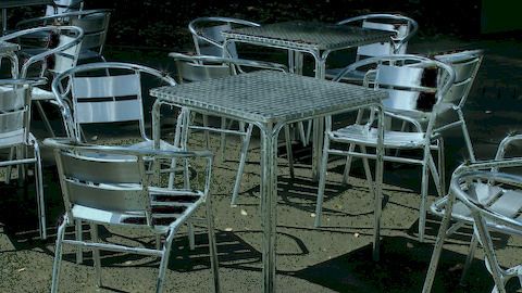
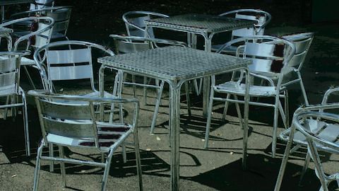
Chapter 1. Introduction 26

orthogonal to one subspace in their 2 chromaticity definition. Their approach required adaptive
clustering for the estimation of region-specific purely diffuse colors.
 Ren et al. [12] introduced a method based on color-lines that jointly estimated illumi-
nant color and recovered diffuse colors by first clustering the image using a modified nearest
neighbor technique and recovering the diffuse coefficient by searching along the radius in a
polar-formulated coordinate system.
 Guo et al. [13] introduced a sparse and low-rank formulation related to the sparse non-
negative matrix factorization approach initially formulated by Akashi and Okatani [10]. They
propose that diffuse weights are few in number and in composition (i.e., that diffuse weights are
both sparse and low rank), and that specular weights are likewise sparse. They introduce two
auxiliary variables to incorporate these formulations and iteratively solve a constrained nuclear
norm and 1 -norm minimization of an augmented Lagrangian function.
 Son et al. [14] modeled the general properties of diffuse and specular reflections in a
convex optimization framework. The authors additionally attack a limitation of specular removal
based on the dichromatic reflection model, specifically that of failing to remove specular reflec-
tions from achromatic regions, by explicitly including generic image priors applicable to natural
images.

1.4.2 Real-Time Methods
 Yoon et al. [6] were the first to introduce the two-band specular-free image, obtained
by subtracting the minimum among the three RGB channels from the input image. They pro-
posed comparing neighbor intensity ratios to corresponding ratios in the two-band specular-free
representation and propagating diffuse ratios. They were also the first to be concerned with the
timeliness of the underlying method for separation of reflection components.
 Shen et al. [8] modified the two-band specular-free image by Yoon et al. [6] to make
its chromaticity more robust to noise by adding an offset. They treated the highlight removal
problem by solving the dichromatic reflection model least-square problem for mixed specular-
diffuse regions with regions that are purely diffuse and have the least distance in chromaticity
coordinates.
 Shen and Cai [25] solved the removal problem by first segmenting into mixed specular
and diffuse and purely diffuse, then correcting the values of specular regions by solving for a
constant adjustment gain under the criterion of smooth color transition along the boundary of
highlight and surrounding regions.
 Yang et al. [9] introduced a real-time method rooted in the chromaticity analysis work
of Tan and Ikeuchi [2]. They proceeded by employing a joint bilateral filter to smooth out the
maximum chromaticity of the observed image, using a specular-free guide that has no specular
geometry features. Specular phenomena are considered noise in this filtering approach. At the
You can also read