RED HILL FUEL STORAGE TANKS - J. David Rogers, Ph.D., P.E., R.G. Karl F. Hasselmann Chair in Geological Engineering
←
→
Page content transcription
If your browser does not render page correctly, please read the page content below
RED HILL FUEL
STORAGE TANKS
  J. David Rogers, Ph.D., P.E., R.G.
 Karl F. Hasselmann Chair in Geological Engineering
             University of Missouri-Rolla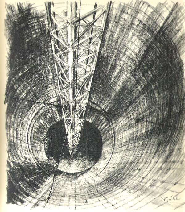
Facts About the Red Hill Storage Tanks
Construction began Christmas 1940,
completed September 1943
Project included 20 cylindrical tanks 100 feet
diameter, 250 feet high
Design capacity of 6 million barrels fuel oil
(255 million gallons)
Final cost: $42 million
16 men died during construction
Project also pumps 30 millions gallons per
day of drinking water to surrounding area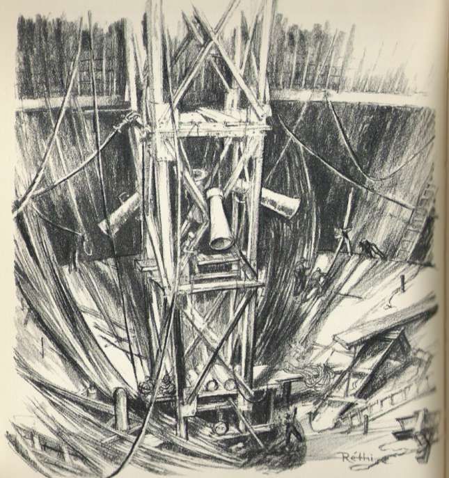
Factors Leading to Construction
Prior to the attack on Pearl Harbor all of the
Navy’s fuel was stored in unprotected above
ground tanks at Pearl Harbor, next to the
submarine base
When RADM Chester Nimitz was
Commander of the Bureau of Yards & Docks
(in 1940) he wanted the Navy’s 2-1/2 year
supply of fuel oil protected from aerial attack
Standard practice was to dig a trench and
bury the tanks, but this was impractical to
store 255 million gallons of fuel oil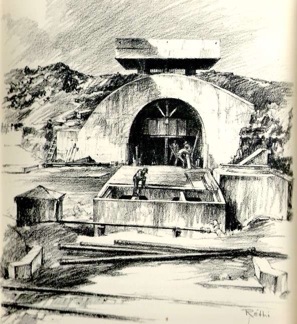
Initial Plan
The Navy’s plan was to dig a series of
tunnels and insert the tanks
Finding a suitable site was problematic,
Oahu is underlain by the Koolau
Volcanic series, and these flows are full
of vugs, clinker, underground streams,
and pools
Navy engineers finally settled on Red
Hill, about two miles from Pearl Harbor,
as it was mostly homogeneous basalt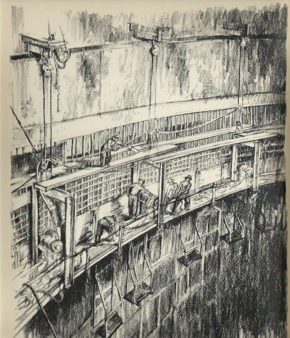
Location of Red Hill and Pearl Harbor
Red Hill
Red Hill was not owned by the Navy, it
was then under cultivation for sugar
cane and pineapple plantations
The Navy leased the land, cleared and
leveled it, then began construction of
temporary work camps
Eventually the plantation owners were
forced to sell out to the Navy through
direct condemnation.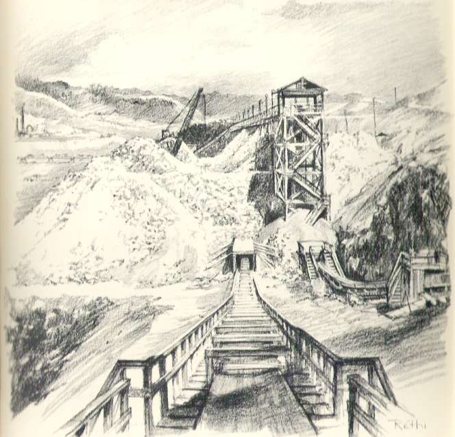
Planning and Development
Consultanting engineer James P.
Growden came up with excavating
large vertical tank chambers instead of
horizontal tunnels
This would increase the volume of
material that could be excavated
simultaneously and decrease the
number of heavy equipment needed for
hauling muck. It also decreased the
unit cost for rock removal substantially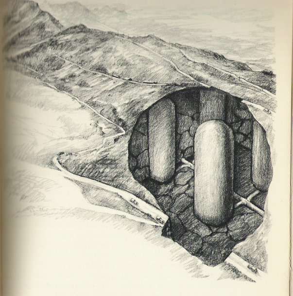
Design
 Concept for
the vertically
   arrayed
storage tanks
Nothing like this
had ever been
attempted
previously
The contractor
used gravity to
“flow” rock muck
to the base of
each cavity
Vertically Aligned Cylinder Tanks
The tanks were set up in two parallel rows
with two main access tunnels, one above the
other, bisecting the rows
Smaller tunnels, or adits, branched from
these main axis tunnels to the tank cavities.
To determine the depth necessary to protect
the fuel from Japanese aerial attack, the
engineers gathered data from the Army,
multiplied it four-fold and rounded the figure
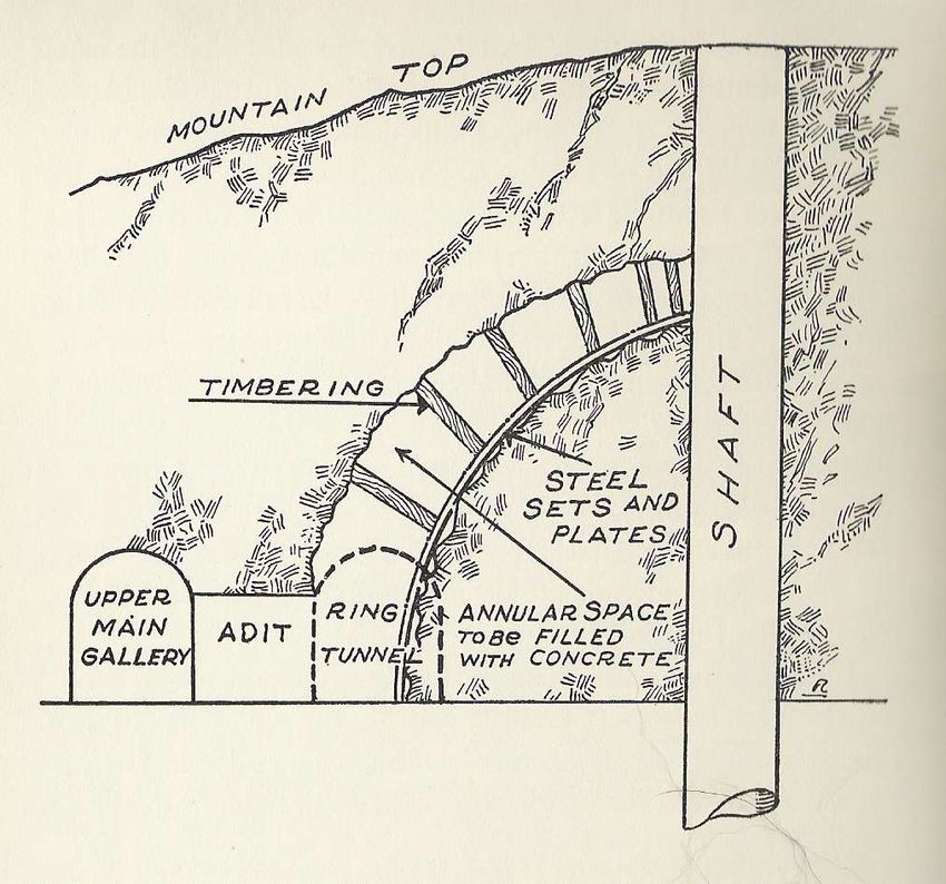
off to 100 feet of rock coverSidehill
entrance to
the tank
excavations
and lower
access
tunnel, as
sketched
during
constructionAccess Tunnels
Once the tank invert level and radius of
curvature were determined digging could
commence.
Both the upper and lower access tunnels
were excavated simultaneously
They were constructed like the horseshoe
shape of railroad tunnels, flat floors and
walls, with an arched ceiling
The tunnels were rough hewn then lined with
concrete for increased strengthChamber Adits
As the main access tunnels moved past the
location of an proposed storage chamber,
more workers began digging the branch
lines, or horizontal adits
The adits were smaller, man sized, and were
shored with steel H-beams bolted together
and sprayed with cement
The lower adit was excavated as far as the
center point of the tank and the upper adits
were stopped when they reached the outer
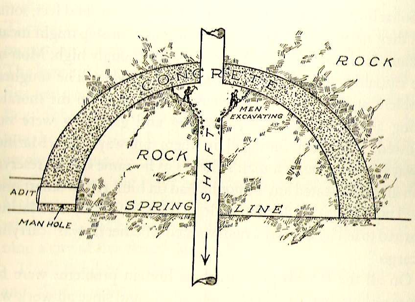
radiusBeginning Tank Chamber Excavation
In the upper adit, once the outer radius of the
tank had been reached, a ring tunnel was
dug around the radius of the tank chamber
Upon completing the ring tunnel, the miners
dug upwards in a hemisphere from all points
around the ring, narrowing as they reached
the central shaft
Meanwhile, a central shaft 8 feet in diameter
was excavated through the central axis of the
chamber, down to the lower aditHow Each Chamber Excavation Began The upper dome of each fuel chamber was excavated first, starting with a ring tunnel, then working upward, towards the central shaft
Forming the Upper Dome
(1 of 2)
Each section of the dome had to be
braced with timber, prefabricated above
ground in the exact curvature of the
dome
This allowed the miners to dig to a
template reducing time of excavation
I beams were then sent down and
assembled to form ribs around the
dome
Sections of steel plate cut to piece
together and form the dome were sent
down and welded togetherForming the Upper Dome
(2 of 2)
The wood shoring had to be shortened
and replaced to account for the H-beam
steel sets and liner plates
A pipe network extending down the
central shaft and radiating around the
dome was constructed for placing
concrete to line the tank chambers
Each chamber dome required 70 hours
of continuous pouring for 5000 cubic
yards of concreteAfterthe upper hemisphere dome was concreted, miners could begin mucking the upper tank chamber, dropping muck by gravity through the central shaft, as shown
Tank Excavation
(1 of 2)
As soon as the upper hemisphere concrete
had set, workers were lowered down the
central shaft to begin excavation of the tank
chamber
The miners dug outwards in all directions
under the dome, keeping a 30 – 45 degree
slope to the center of the shaft, so muck
would slide into the shaft by gravity, greatly
reducing mucking labor and transport for the
project
At the bottom of the vertical shaft rock
screens (grizzlies) broke up falling rock so it
could be transported on conveyorsTank Excavation
(2 of 2)
In the lower adits an elaborate
conveyer belt system was constructed
to carry mucked rock out of the
excavations
The central tank shafts were expanded
in a cone under the upper dome until
the desired diameter was reached
Following the deaths of a few workers
falling down the central shaft, planks
were rigged to the dome for them to
stand onSketch of a
tank’s lower
hemisphere
under
construction
being lined
with concrete
with an inner
steel liningFinishing Excavation
The miners continued to dig
downwards in a cone until they reached
the lower hemisphere of the tank
chamber
The lining for the lower hemisphere
was placed similarly to the top
Any cracks or holes found during
excavation were grouted and sealedLining the
walls of the
tank chamber
Reinforced
concrete was
placed against
the rock and
smooth
continuously
welded steel
plate formed
the inner linerConstructing the Tank Liner
Rings of steel ribs were constructed
above ground and sent into the shaft
for assembly
Once a skeleton was assembled
through the entire shaft, steel plate was
welded around the ribs to form the
tank’s inside liner
Concrete was poured into the space
between the tank liner and the rockConstruction
of the Tank
Walls
This view
shows the
concrete liner
being poured
against the
rock face near
the bottom of a
chamberFinishing the Tank Chambers
Once the concrete had set, high
pressure grout was injected into the
tension cracks and spaces remaining
between the concrete and the tank
The Navy filled each tank with water to
perform leak tests
If there was more than a ½ inch drop in
24 hours from a pipe on top the tank
chamber, they failed the testChecking for
Leaks
This sketch
shows water
being fed
into the tank
chamber for
a leak testFixing Leaks
In order to locate the leaks, the tanks were
filled very slowly with water, as high
pressure air was injected outside the tank
Welders in boats on the slowly rising pool of
water would look for the bubbles of air
entering the tank’s steel lining, signal for the
water level to be lowered and then weld the
seam
Two men drowned when the water level was
raised too quickly and their boat capsizedProtected Entrance to one of the Permanent Access Tunnels
Finishing Construction
When each tank was complete the top was
closed and the access shafts above the tank
chambers were filled with concrete
The Navy also had constructed a tunnel from
the Red Hill Fuel Storage Facility to Pearl
Harbor and installed a high pressure pipe
line to handle the flow of oil to the harbor
The entrance to these tunnels are all
hardened, being concrete encased with blast
doors. Additional doors are also installed
throughout the portal tunnels to prevent
accidental discharge of fuelEnvironmental Problems
Despite all the leak testing during
construction (60+ years ago), leaks still
occur
Several sites have been used over the
years for storage of waste
Environmental remediation is
underway to remove contaminated soil
and create a leak proof spill siteReferences
Builders for Battle: How the Pacific
Naval Air Bases Were Constructed,
David O. Woodbury, E.P. Dutton & Co.,
New York, 1946, 415 pages.
http://www.asce.org/history/build_redhi
ll.swf
Dr. Rogers’ consultations for Navy
Facilities Engineering Command
Western DivisionYou can also read