REDOX FLOW BATTERIES - Sandia National ...
←
→
Page content transcription
If your browser does not render page correctly, please read the page content below
CHAPTER 6
REDOX FLOW BATTERIES
Leo J. Small, Cy H. Fujimoto, Harry D. Pratt III, Travis M. Anderson, Sandia National
Laboratories
Abstract
Redox flow batteries (RFBs) offer a readily scalable format for grid scale energy storage. This
unique class of batteries is composed of energy-storing electrolytes, which are pumped through a
power-generating electrochemical cell and into large storage tanks. Despite this common
underlying design, a myriad of different electrolyte chemistries and electrochemical cell designs
have been investigated, some of which have been successfully commercialized. This chapter
reviews state-of-the-art flow battery technologies, along with their potential applications, key
limitations, and future growth opportunities.

Key Terms
anolyte, catholyte, flow battery, membrane, redox flow battery (RFB)

1.   Introduction
Redox flow batteries (RFBs) are a class of batteries well-suited to the demands of grid scale energy
storage [1]. As their name suggests, RFBs flow redox-active electrolytes from large storage tanks
through an electrochemical cell where power is generated [2, 3]. The electrolytes are specifically
designed such that they can be electrochemically reduced (accept electrons) or oxidized (provide
electrons) [4]. One tank of the flow battery houses the cathode (catholyte or posolyte), while the
other tank houses the anode (anolyte or negolyte). Figure 1 is a schematic of a typical, single cell
flow battery used for research and development. Here the catholyte (green) is housed in the tank
on the left, while the anolyte (blue) is housed in the tank on the right. These electrolytes are flowed
through the serpentine flow field of the electrochemical cell at the center of the figure. The flow
field is commonly made from carbon and serves as the current collector as the electrolytes are
oxidized and reduced. Adjacent to the flow fields reside porous carbon electrodes, maximizing the
contact area with the liquid electrolyte. Between the porous carbon electrodes resides a separator.
Typically, the separator is an ion-selective membrane such as Nafion [5, 6] Such membranes
enable transport of inert ions necessary to charge-balance the electrochemical reactions, while
preventing electronic shorting of the opposing carbon electrodes and physical mixing of anolyte
and catholyte.

                                                  1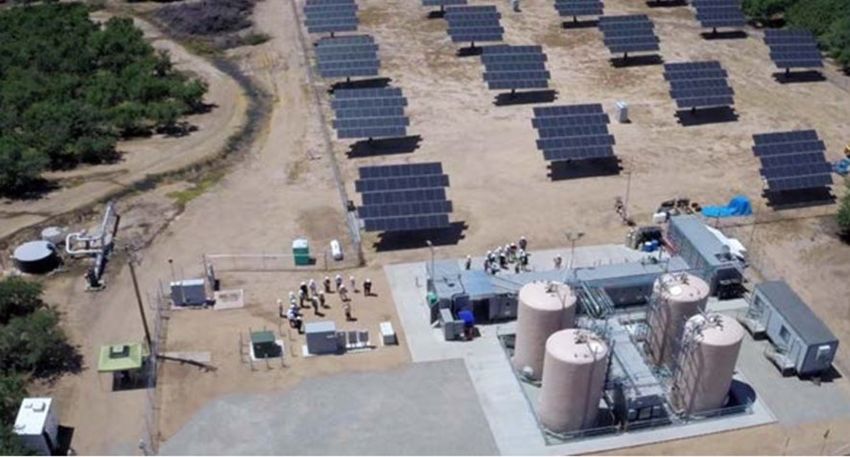
Chapter 6 Redox Flow Batteries
Figure 1. Schematic of a single cell RFB, depicting electrolyte flowing from storage tanks through
the serpentine flow field within the electrochemical cell
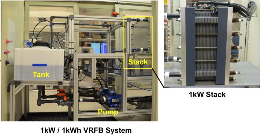
To generate higher power necessary for practical applications, many flow cells are strung together.
Figure 2 shows a photograph of a 1 kW/1 kWh vanadium RFB test bed used at Pacific Northwest
National Laboratory (PNNL) [7]. An enlarged view is provided of the 1 kW cell stack, consisting
of 15 cells strung together between the thick steel plates. Here, the 15 cell electrodes are placed in
series, increasing the stack voltage by a factor of 15, while the anolyte and catholyte are pumped
in parallel through each cell individually.
2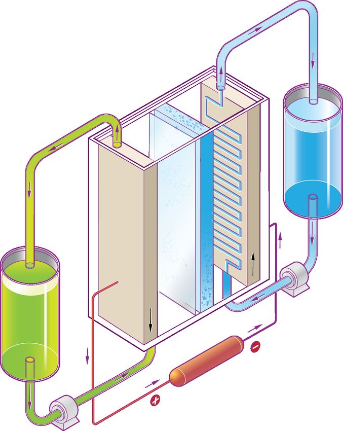
Chapter 6 Redox Flow Batteries

 Figure 2. Photograph of vanadium RFB (VRFB) test bed developed at Pacific Northwest National
Laboratory for RFB evaluation. A zoomed in image of the electrochemical cell stack is provided at
                                             right.

Flow batteries are particularly attractive for their ability to decouple energy and power. The
specific choice of catholyte and anolyte chemistry will dictate the voltage of an individual cell and
the energy density of the system. Therefore, the overall energy of a flow battery may be controlled
by varying the volume of electrolyte. On the other hand, the power can be effectively manipulated
through design of the electrochemical cell. Thus, a high energy flow battery aimed at long duration
discharge might couple large volumes of electrolyte with a modestly sized electrochemical cell,
whereas a high power, short duration flow battery might only require smaller volumes of
electrolyte but leverage a significantly larger electrochemical cell.
Flow batteries offer several potential safety features compared to regular, nonflowing batteries.
Unlike traditional batteries, the bulk of the anolyte and catholyte are spatially separated from each
other in large tanks. Thus, it is considerably harder to release all the stored energy under
nonstandard or emergency conditions. Even if the electrochemical cell were to rupture, valves
could be closed and the anolyte and catholyte would remain separated. Moreover, most flow
batteries commercialized today use aqueous-based electrolytes, rendering them nonflammable.
Depending on the exact electrolyte chemistry employed, flow batteries can also be non-toxic and
non-corrosive.

2.   State of Current Technology
2.1. Current Implementation

2.1.1. Electrolyte Chemistries
A variety of different electrolyte chemistries exist in the flow battery market. Currently
commercialized electrolytes almost exclusively use aqueous (water-based) electrolytes. The exact
electrolyte formulation largely dictates the cell voltage, energy density, and operating temperature
range of the RFB. The following discussion outlines several classes of electrolyte chemistries that
have been commercially evaluated. This discussion is not meant to be an exhaustive list. As of the

                                                 3
Chapter 6 Redox Flow Batteries
time of writing, over 100 different companies are developing RFBs, each with their own electrolyte
formulations.
2.1.1.1. Iron-Chromium
Originally invented by NASA in the late 1970s, the iron chromium (Fe-Cr) system was the first
RFB electrolyte system developed [8, 9]. It consists of an Fe2+/3+ catholyte coupled with a Cr2+/3+
anolyte in an acidic aqueous electrolyte. On discharging, the following redox reactions occur:
Catholyte: Fe3+ +e- Fe2+ E0= 0.77 vs. SHE (1)
Anolyte: Cr2+ Cr3+ + e- E0= -0.41 vs. SHE (2)
A cell voltage of 1.2 V is typical, with metal ions dissolved at ~1 M concentrations. In general, the
Cr2+/3+ redox reactions are sluggish compared to other chemistries, requiring use of a catalyst [3].
Moreover, the dissimilar catholyte and anolyte mean that transport of catholyte to anolyte, and
vice versa, leads to permanent loss in battery capacity. Nevertheless, NASA has demonstrated this
chemistry on a 1kW/13kWh scale, and even larger scale by others, as described later in this
chapter.
2.1.1.2. All-Vanadium
Currently, the most widely commercialized RFBs all use vanadium-based electrolytes. The basis
for this chemistry was first developed by Skyllas-Kazacos and coworkers in 1984 [10, 11] Here,
the anolyte and catholyte both consist of aqueous acidic solutions of vanadium. Using the same
electrolyte for anolyte and catholyte is beneficial in that if transport of one to another occurs it
does not permanently damage RFB capacity. Upon discharge, the following redox reactions occur
in a vanadium RFB:
Catholyte: V5+ + e- V4+ (3)
Anolyte: V2+ V3+ + e- (4)
Note that the V5+ and V4+ are typically oxo-complexes such as VO2+ and VO2+, respectively.
Vanadium concentrations are typically on the order of 1-3 M. Coupled with a nominal cell voltage
of 1.6 V, an energy density of around 20 Wh/L is observed. The exact composition of the
electrolyte is the focus of much research, with various groups experimenting with different acid
types, complexing agents, and vanadium purities, leading to improvements in operating
temperature and energy density, among others [2, 12, 13].
2.1.1.3. All-Iron
To decrease the cost of RFBs, researchers have developed all-iron systems. There are several
variations of this chemistry, though fundamentally all employ the Fe2+/3+ couple in the anolyte.
The catholyte may contain the Fe2+/0 couple or the Fe2+/3+ complexed with different ligands from
those in the anolyte. Use of the Fe2+/0 couple requires electroplating solid Fe metal on the anode
while charging. Sometimes the use of a solid electrode in an RFB is referred to as a “hybrid redox
flow battery.” The catholyte chemistry can be fairly sophisticated, with various Fe-complexes
(e.g., Fe(CN6)3-/4-) tailored to enhance RFB cell voltage and stability [14-16]. The exact cell
voltage depends on the chemistry employed but is typically in the 0.75-1.2 V range.
4
Chapter 6 Redox Flow Batteries
2.1.1.4. Zinc-Bromine
Perhaps the most complicated of all the commercialized RFB electrolyte chemistries is Zinc-
Bromine (Zn-Br). Here, metallic zinc is plated and stripped on the anode, while liquid bromine is
evolved and reduced from the cathode. Like the all-Fe RFB, the Zinc-Bromine RFB can be
considered a “hybrid flow battery.” Upon discharge of the RFB, the following redox reactions
occur:
Catholyte: Br2 + 2e- 2Br- (5)
Anolyte: Zn0 Zn2+ + 2e- (6)
The relatively high theoretical cell voltage of 1.82 V, coupled with the high electrolyte
concentrations, enable an energy density of 60-70 Wh/L. This chemistry is more complicated than
others in that multiple phase-change reactions occur. Whereas with most of the previous electrolyte
chemistries all reagents remain in the liquid phase, here zinc is electroplated out as a solid and
bromine is evolved into the liquid phase. Advanced complexing agents are added to the electrolytes
to stabilize Br- and Zn-containing species and minimize the Br2 vapor pressure and Zn dendritic
growth [17, 18, 19].
2.1.2. Separators
The primary role of the membrane separator is to allow the flow of electrolyte between the positive
and negative compartments for charge balance, while preventing the transport of electroactive
species, which leads to capacity decay. Other key attributes of the membrane are high
oxidative/reductive stability, flexible mechanical properties, and low cost. The membrane
separator is a critical component to flow battery performance, durability, and cost. However, a
membrane that satisfies all the mentioned requirements does not exist, thus current research efforts
are focused on a variety of membrane composition and morphology to optimize flow battery
performance.
There are two broad categories of flow battery membranes: 1) ion exchange membranes: dense
film with ionic moieties that are tethered to a hydrocarbon or perfluorinated backbone, which
instills hydrophilic character, and 2) porous membranes with nonionic polymer backbone and
engineered pore size/density. Both types of membranes have positive attributes, but also have
properties that need to be further improved, which will be discussed in Section 2.3.2 Membranes.
There are two types of ion exchange membranes that are differentiated by the type of bound charge
in the polymer backbone. The bound charges in the polymers develop a Donnan potential, which
determines the ion selectivity of the membrane.
Cation exchange membranes (CEM) have fixed negative charges with a negative Donnan potential
that predominantly allows cation mobility through the membrane. The opposite is found in anion
exchange membranes [20, 21]. The attached negative charge is typically a sulfonate moiety, due
its stability and high ion dissociation values. However, carboxylate and phosphonate groups have
also been investigated. The state-of-the-art of cation exchange membranes are perfluorinated
sulfonic acid (PFSA) such as Nafion (Chemours), Aciplex (Asahi) or Flemion (AGC). These types
of membranes are industrially employed in the chloro-alkali process and used in large
demonstration-size acidic vanadium and Fe-Cr flow batteries due to low proton resistance and
superior chemical durability. The primary downside to PFSA membranes is high cost, which
accounts for up to 30-40% of the stack hardware [22, 23]. Sulfonated hydrocarbon polymers are
being developed as low cost alternatives to PFSA due to inexpensive chemical feedstock and
5
Chapter 6 Redox Flow Batteries

benchtop preparation [24]. The wide diversity of hydrocarbon backbones—poly(arylene ether
ketone), poly(styrene), poly(phenylene oxide), poly(phenylene), etc.—and precise control of ion
content levels allow for chemically engineered membranes with low proton resistance and high
ion transport selectivity. The key deficiency, and what R&D efforts seek to improve, is the
oxidative durability of sulfonated hydrocarbon membranes compared to PFSA type material.
Anion exchange membranes (AEMs) contain fixed positive charges and have positive Donnan
potentials. The positive charge is typically a variant of an ammonium moiety, however
imidazolium, phosphonium and guadindium are also being developed. Unlike CEMs, there is no
large end user (such as with the chloro-alkai process) that employs AEMs, which have primary
use in membrane-based water treatment [25]. However, AEMs have been employed in vanadium
RFB by Kashim-Kita Electric Power Corporation and Sumitomo Electric Industries in a 200kW x
4 h demonstration system [26, 27]. The advantage of AEMs in vanadium RFBs is lower vanadium
permeability through the membrane due to the Donnan exclusion effect, however, concerns over
lower proton conduction and long-term stability are valid [28]. Other opportunities for AEMs are
in neutral and high pH environments that are being developed in aqueous organic flow batteries
[29, 30]. Unlike CEMs, there is no state-of-the-art material (such as PFSA) in AEMs because of
three different durability concerns in alkaline media that current R&D efforts seek to improve:
1) backbone stability 2) positive moiety stability, and 3) oxidative stability [31, 32].

2.1.3.    Integration with the Electric Grid
RFBs come in a range of sizes, from small 1 kWh residential systems, to multi-MWh industrial
systems. While significant variability in form-factor and enclosure design exists at the smaller
scale, large industrial systems are usually packaged in shipping containers. These containers
typically house all RFB systems—electrolyte storage tanks, pumps, electrochemical cell stack—
along with power electronics necessary to connect the DC power of the flow battery to the AC
power of the residential, commercial, or industrial-level electric grid. Details on power electronics
can be found in Chapter 13: Power Conversion Systems.

2.1.4. Major Players
Of the more-than 100 RFB companies currently working in the industry, most are start-ups
developing new RFB technologies, particularly electrolytes. Large established corporations such
as Sumitomo Electric Industries, a large Japanese multinational corporation, and Dalian Rongke
Power Co. dominate large utility scale projects. Other manufacturers include UniEnergy
Technologies, Primus Power, StorEn, Redflow, RedT Energy, and Avalon, among others. Many
large industrial companies conduct research into RFBs and license their technologies to startups,
such as the relationship with United Technologies and the startup Vionx. Other large corporations,
such as Lockheed Martin, have also directly entered the RFB business, recognizing that energy
storage will become a ubiquitous part of the national electrical grid and a strategic asset in defense
applications.

2.1.5.    Deployment Examples
Over the past decade, many different RFB systems have been deployed throughout the world.
While their total capacity pales in comparison to overall electrical power consumption, these RFB
installations provide pertinent use-case information and demonstrate how RFBs can successfully
be integrated with the electric grid.

                                                  6
Chapter 6 Redox Flow Batteries
At the small-to-medium scale, Australian company RedFlow has achieved success deploying their
Zn-Br based systems on residential (~20-60 kWh) to commercial and industrial customers (~100
kWh). When coupled with solar power, these systems have enabled customers to operate off-grid.
At the commercial level, these systems provide flexibility in power time of use and allow
companies to keep the lights on during blackouts [33].
RFBs have been successfully coupled with industrial agriculture in the Central Valley of
California. In 2014, EnerVault Corp. successfully demonstrated a 250kW/1MWh Fe-Cr RFB that
was charged by a 150 kW PV system or the grid and used to run a ground water irrigation pump.
An aerial photo of this installation is provided in Figure 3. EnerVault leveraged several proprietary
designs to improve RFB technology and successfully deploy this Fe-Cr RFB [34]. While the
project was a technical success, EnerVault filed for restructuring in 2015.
Figure 3. Photograph of EnerVault Corp.’s 250kW/1MWh Fe-Cr RFB in Turlock, California.
Electrolyte is held in the four tanks in the lower right [34].
UniEnergy Technologies has integrated several RFBs into the electrical grids across Washington
State. A 1MW/4MWh system was installed in Pullman, WA, using both grid-tied and islanding
operations. A 2MW/8MWh vanadium RFB installed in Everett, WA was successful in shifting
peak demand, improving electrical power distribution, and enhancing grid voltage control [35].
The largest RFB built to date resides in Dalian, China, where Rongke Power is constructing a
200MW/800MWh vanadium RFB, with completion scheduled in 2020. The RFB is targeted at
peak-shaving applications, easing grid strain under extreme weather conditions. Despite the RFB
large capacity, this represents about 8% of total projected electrical grid load in Dalian [36].
2.2. Challenges
The main challenges facing RFBs are related to cost and energy density. Decreasing the cost of
electrolyte and membrane materials would go a long way toward increasing RFBs’
competitiveness against other energy storage technologies on a $/kWh scale. However, the active
ingredient in many RFBs, vanadium, is costly, as are the ion exchange membranes used as
7Chapter 6 Redox Flow Batteries
separators (Nafion). Additionally, these separators often provide less than ideal electrochemical
performance, decreasing battery performance over time.
While flammability is often not a hazard for RFBs, as most electrolytes are aqueous-based, many
of the electrolytes are toxic and corrosive. Coupled with RFBs’ low energy density, this implies a
large volume of hazardous material is required to store energy. This hazardous material may limit
installation sites and require special permitting.
Last, some RFB chemistries are sensitive to extreme temperatures (e.g., >40°C, 1 M are
achievable and might allow these technologies to be viable if long term stability can be proven
[39, 40]. While nonaqueous electrolytes promise more energy-dense RFBs, membranes tailored
for specific nonaqueous electrolytes will need to be developed to enable their long-term success
[41]. Moreover, electrolytes will need to be carefully chosen to satisfy safety requirements.
2.3.2. Membranes
To improve the transport selectivity of ion exchange membranes, CEM and AEM can be combined
either by spray coating or electro spraying to form a bipolar membrane [42]. This type of
asymmetric membrane improves flow battery performance by reducing capacity fade and
excessive electro osmosis, however R&D will need to focus on improving ion
conductivity/membrane interface, durability, and cost of production [43, 44].
Porous membranes are films with specific pore size and pore density and are commonly used in
lead acid, zinc and Li-ion batteries. Well known examples of porous, commercially available
membranes are Celgard and Daramic. These films are composed of uncharged polymers such as
poly(ethylene) or poly(propylene) that are either extruded then stretched to form pores (dry
8Chapter 6 Redox Flow Batteries
process) or the polyolefin resin is mixed with a hydrocarbon liquid; the melt is extruded, oriented,
and the liquid phase extracted (wet process). The advantage of these materials is their relatively
low costs, compared to PFSA and their durability in electrochemical environments. The
disadvantage of these materials in flow batteries, however, is transport selectivity, because the
permeation of species through the membrane is regulated only by size exclusion. R&D in this area
seeks to control pore size/density synthetically; recent review papers provide more details [45, 46].
3. Concluding Remarks
RFBs offer a unique, adaptable solution to meet a wide range of energy storage requirements of
the future. By decoupling energy and power, RFBs can be designed for a range of energy storage
and power demands. The near limitless possibilities for electrolyte chemistries further play to
RFBs advantage, allowing them to stay at the cutting edge while other more traditional chemistries
(e.g. Pb-acid) rise and fall. Moreover, several key features of RFBs can make them significantly
safer than other electrochemical energy storage technologies. In sum, the push toward longer
duration energy storage, firming up wind and solar resources, coupled with the drive for safer,
less-flammable energy has put flow batteries in a unique position to increase market share in the
near future.
Leo J. Small is a materials scientist and electrochemist at Sandia National
Laboratories in Albuquerque, New Mexico. His work focuses on
understanding and manipulating ion movement in electrochemical and
energy storage systems. Dr. Small received his bachelors from Cornell
University and PhD from Rensselaer Polytechnic Institute, both in
Materials Science.
Cy H. Fujimoto is a polymer chemist at Sandia National Laboratories in
the Nanoscale Sciences Department. His work has been developing
membranes for electrochemical systems. Dr. Fujimoto obtained his PhD in
inorganic chemistry from the University of California, Irvine in 2001.
Harry D. Pratt III is a distinguished technologist in the Advanced Power
Sources R&D group at Sandia National Laboratories. Since 2011, Harry
has assembled, tested, and optimized hundreds of flow batteries across a
wide variety of chemistries.
9Chapter 6 Redox Flow Batteries
Travis M. Anderson is a distinguished staff member in Sandia National
Laboratories’ Advanced Power Sources Research and Development
group. Travis obtained his PhD in inorganic chemistry from Emory
University in 2002. He has over 10 years’ experience in advanced energy
materials research and development. His research interests focus around
the synthesis and characterization of redox-active coordination complexes,
flow batteries, and thermal battery aging.
10Chapter 6 Redox Flow Batteries
References
[1] B.R. Chalamala, T. Soundappan, G.R. Fisher, M.R. Anstey, V. V. Viswanathan, and M.
L. Perry, “Redox Flow Batteries: An Engineering Perspective.” Proc. IEEE. DOI:
10.1109/JPROC.2014.2320317
[2] M. Skyllas-Kazacos, M. H. Chakrabarti, S. A. Hajimolana, F. S. Mjalli, and M. Saleem.
“Progress in Flow Battery Research and Development.” J. Electrochem. Soc. 158 R55-
R79 (2011).
[3] A. Z. Weber, M. M. Mench, J. P. Meyers, P. N. Ross, J. T. Gostick, and Q. Liu. “Redox
flow batteries: a review.” J. Appl. Electrochem. 41 1137-1164 (2011).
[4] M. Park, J. Ryu W. Wang, and J. Cho. “Material design and engineering of next-
generation flow-battery technologies.” Nat. Rev. Mater. 2 16080-16098 (2017).
[5] S. Maurya, S.-H. Shin, Y. Kim, S.-H. Moon. “A review on recent developments of anion
exchange membranes for fuel cells and redox flow batteries.” RSC Adv. 5 37206-37230
(2015).
[6] B. Schwenzer, J. Zhang, S. Kim, L. Li, J. Liu, and Z. Yang. “Membrane Development for
Vanadium Redox Flow Batteries.” ChemSusChem 4 1388-1406 (2011).
[7] V. Sprenkle, W. Wang, D. Reed, E. Thomsen, Z. Nie, B. Li, X. Wei, B. Koeppel, B.
Chen, A. Crawford, and V. Viswanathan, ‘‘Next generation redox flow battery
development at PNNL.’’ in Proc. Mater. Res. Soc. Fall Meeting, Boston, MA, USA, Dec.
2, 2013, pp. 11–18.
[8] L.H. Thaller (1974) NASA TM-X-71540.
[9] L.H. Thaller (1979) NASA TM-79143, DOE/NAA/1002-79/3.
[10] M. Skyllas-Kazacos and R. Robins, U.S. Pat. 4,786,567 (1986).
[11] M. Skylass-Kazacos, R. Robins, M.A. Green and A. J. Fane, “Final Report for NERDDC
Grant No. 788.” (Dec. 1986).
[12] L. Li, S. Kim, W. Wang, M. Vijayakumar, Z. Nie, B. Chen, J. Zhang, G. Xia, J. Hu, G.
Graff, J. Liu, and Z. Yang. “A Stable Vanadium Redox-Flow Battery with High Energy
Density for Large-Scale Energy Storage.” Adv. Energ. Mater. 1 394-400 (2011).
[13] M. L. Perry and A. Z. Weber. “Advanced Redox-Flow Batteries: A Perspective.” J.
Electrochem. Soc. 163 A5064-5067 (2016).
[14] K. L. Hawthorne, J. S. Wainright, and R. F. Savinell. “Studies of Iron-Ligand Complexes
for an All-Iron Flow Battery Application.” J. Electrochem. Soc. 161 A1662-A1671
(2014).
[15] K. Gong, F. Xu, J. B. Grunewald, X. Ma, Y. Zhao, S. Gu, and Y. Yan. “All-Soluble All-
Iron Aqueous Redox-Flow Battery.” ACS Energy Lett. 1 89-93 (2016).
[16] B. S. Jayathilake, E. J. Plichta, M. A. Hendrickson, and S. R. Narayanan. “Improvements
to the Coulombic Efficiency of the Iron Electrode for an All-Iron Redox-Flow Battery.”
J. Electrochem. Soc. 165 A1630-A1638 (2018).
11Chapter 6 Redox Flow Batteries
[17] P. C. Butler, P. A. Eidler, P. G. Grimes, S. E. Klassen, and R. C. Miles. “Advanced
Battery Systems.” Sandia National Laboratories. Report SAND2000-0893. (2000).
[18] D. J. Eustace. “Bromine Complexation in Zinc-Bromine Circulating Batteries.” J.
Electrochem. Soc. 528 528-532 (1980).
[19] A. Leo. “Zinc Bromide Battery Development.” Energy Research Corporation for Electric
Power Research Institute, Project 635-3, EM-4425, (1986).
[20] H. Strathmann, Ion-Exchange Membrane Separation Processes, Elsevier B.V,T.
Amsterdam, San Diego, Oxford, London, 2004.
[21] Luo et al. J. Membrane Sci. 555 429–454 (2018).
[22] V. Viswanathan, A. Crawford, D. Stephenson, S. Kim W. Wang, B. Li, G. Coffey, E.
Thomsen, G. Graff, P. Balducci, M. Kintner-Meyer and V. Sprenkle. “Cost and
Performance Model for Redox Flow Batteries.” J. Power Sources 247 1040-1051 (2014).
[23] C. Minke, U. Kunz, T. Turek. “Techno-economic assessment of novel vanadium redox
fow batteries with large-area cells.” J. Power Sources 361 105-114 (2017).
[24] M. A. Hickner, H. Ghassemi, Y. S. Kim, B. R. Einsla, and J. E. McGrath. “Alternative
Polymer Systems for Proton Exchange Membranes.” Chem. Rev. 104 4587-4612 (2004).
[25] T. Davis, D. Genders, and D. Pletcher. A First Course in Ion Permeable Membranes.
Romsey, England: Electrochemical Consultancy, 1997.
[26] A. Shibata and K. Sato. “Development of vanadium redox flow battery for electricity
storage.” Power Eng. J. 13 130-135 (1999).
[27] H. Prifti, A. Parasuraman, S. Windari, T. M. Lim, and M. Skyllas-Kazacos. “Membranes
for Redox Flow Battery Applications.” Membranes 2 275-306 (2012).
[28] T. Mohammadi and M. Skyllas-Kazacos. “Evaluation of the chemical stability of some
membranes in vanadium solution.” J. Appl. Electrochem. 27 153-160 (1997).
[29] J. Luo, B. Hu, C. Debruler, and T. L. Liu. “A π-Conjugation Extended Viologen as a
Two-Electron Storage Anolyte for Total Organic Aqueous Redox Flow Batteries.”
Angew. Chem. Int. Ed. 57 231-235 (2018).
[30] K. Lin, Q. Chen, M. R. Gerhardt, L. Tong, S. B. Kim, L. Eisenach, A. W. Valle, D.
Hardee, R. G. Gordon, M. J. Aziz, and M. P. Marshak. “Alkaline Quinone Flow Battery.”
Science, 349 1529-1532 (2015).
[31] E. J. Park and Y. S. Kim. “Quaternized aryl ether-free polyaromatics for alkaline
membrane fuel cells: synthesis, properties, and performance – a topical review.” J.
Mater. Chem. A 6 15456-15477 (2018).
[32] C. G. Arges and L. Zhang. “Anion Exchange Membranes’ Evolution toward High
Hydroxide Ion Conductivity and Alkaline Resiliency.” ACS Appl. Energy Mater., 1 2991-
3012 (2018).
[33] “Zcell - Residential” https://redflow.com/products/redflow-zcell/. Accessed July, 20,
2020.
12Chapter 6 Redox Flow Batteries
[34] C. Horne, R. Mosso, T. Smith and B. Adams. “Demonstration of EnerVault Iron-
Chromium Redox Flow Battery.” California Energy Commission. Energy Research and
Development Division, Final Project Report. (2015) CEC-500-2015-051.
[35] “Unienergy Technologies” www.uetechnologies.com. Accessed July, 20, 2020.
[36] Z. Gary Yang. “Is this the ultimate grid battery?” IEEE Spectrum. Nov. 2017.
[37] S. R. Narayan, A. Nirmalchandar, A. Murali, B. Yang, L. Hoober-Burkhardt, S.
Krishnamoorthy, and G. K. Surya, Prakash. “Next-generation aqueous flow battery
chemistries.” Current Opin. Electrochem. 18 72-80 (2019).
[38] J. Luo, B. Hu, M. Hu, Y. Zhao, and T. L. Liu. “Status and Prospects of Organic Redox
Flow Batteries towards Sustainable Energy Storage.” ACS Energy Lett. 4 2220-2240
(2019).
[39] R. W. Hogue and K. E. Toghill. “Metal coordination complexes in nonaqueous redox
flow batteries.” Current Opin. Electrochem. 18 37-45 (2019).
[40] K. Gong, Q. Fang, S. Gu, S. F. Y. Li, Y. Yan. “Nonaqueous redox-flow batteries: organic
solvents, supporting electrolytes, and redox pairs.” Energ. Environ. Sci. 8 3515-3530
(2015).
[41] S.-H. Shin, S.-H. Yun, and S.-H. Moon. A review of current developments in non-
aqueous redox flow batteries: characterization of their membranes for design perspective.
RSC Adv. 3 9095-9116 (2013).
[42] F. J. Oldenburg, E. Nilsson, T. J. Schmidt, and L. Gubler. Tackling Capacity Fading in
Vanadium Redox Flow Batteries with Amphoteric Polybenzimidazole/Nafion Bilayer
Membranes. ChemSusChem 12 2620- (2019).
[43] F. J. Oldenburg, T. J. Schmidt, and L. Gubler. “Tackling capacity fading in vanadium
flow batteries with amphoteric membranes.” J. Power Sources, 368 68-72 (2017).
[44] L. Gubler. “Membranes and separators for redox flow batteries.” Current Opin.
Electrochem., 19 31-36 (2019).
[45] Z. Yuan, H. Zhang, and X. Li. “Ion conducting membranes for aqueous flow battery
systems.” ChemComm., 54 7570-7588 (2018).
[46] X. Wei, B. Li, and W. Wang. “Porous Polymeric Composite Separators for Redox Flow
Batteries.” Polymer Reviews 66 247-272 (2015).
13You can also read


