REMOTE CONTROL MODULE BIENEREMOTE128GM-METEO BIENEREMOTE128GM-WS FOR ULTIMETER WEATHER STATION PEET BROS CO., WWW.PEETBROS.COM WITH INTERNAL ...
←
→
Page content transcription
If your browser does not render page correctly, please read the page content below
BieneRemote128GM Data Sheet

                                             Remote Control Module
                                       BieneRemote128GM-METEO
(                                          BieneRemote128GM-WS)
                                  for ULTIMETER® Weather Station
                                  (Peet Bros Co., www.peetbros.com)

                                          with internal GSM modem
                                                     Board Rev.: GM128
                                                     Document Rev.: 1.2
                                               Revision Date: 09.12.2006

                                               www.bieneelectronics.com
                                                 info@bieneelectronics.com

                              1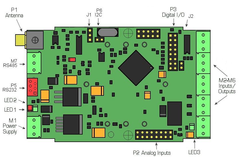
BieneRemote128GM Data Sheet

Introduction

BieneRemote128GM-METEO (BieneRemote128GM-WS) is module with built-in GSM modem for
meteo information monitoring with data logging function.
BieneRemote128GM-METEO designed to be used for Weather Station ULTIMETER 100 (Peet Bros.
Company Inc. - http://www.peetbros.com) remote monitoring.

Features

•   Communication via GSM
•   GSM band -
    900/1800, 900/1800/1900, 850/900/1800/1900
•   GSM receiver and transmitter - internal GSM modem Telit GM862-QUAD
•   Embedded Software
•   Meteo information with SMS
•   Meteo information to FTP server
•   Event notification via SMS
•   GPRS Data Logger
•   Remote control via SMS (turn equipment on and off at any location via GSM)
•   Simple for installation via PC serial port or via SMS.

Applications
   • Remote control
   • Remote monitoring
   • Remote telemetry

                                                 2
BieneRemote128GM Data Sheet

Technical Specification

BieneRemote128GM-METEO Hardware Specification
                                                     BieneRemote128GM-METEO
 Communication                                        GSM850/900/1800/1900
 Command and data transmission                            SMS, GPRS/FTP
 Internal GSM modem                                     Telit GM862-QUAD
 SIM card reader                                                Yes
 SIM card type                                       Phase 2 GSM11.14 - SIM 3V
 Firmware                                                       Yes

 Weather Station Compatibel                      ULTIMETER® 100 Weather Station
                                                 (Peet Bros. Co., www.peetbros.com)
 Meteo information format                                         text
 Transfer meteo information to                                SMS, FTP

 Digital inputs
 Number of digital inputs                                        4
  - Transistor digital input       4 ("0": 0...+1V; "1": +1.5…+12V without external limited resistor)
  - Events digital inputs                                        4
 Analog inputs
                                   Without analog adapter #4A              With analog adapter #4A
 Number of analog inputs                                           2
   - Input                             0…+5V; 100Mom                                0..+16V
   - Battery control                        No                                        Yes
   - Protection                             No                                        Yes
 - Analog event inputs                                            2
 ADC resolution                                                 10 bits
 Battery control                               No                                      Yes
                                                                           (if Battery output connect
                                                                                to analog input 1)

 Outputs
 Number of outputs                                                5
   - MOSFET Open Drain                                            4
 outputs                                         (MOSFET SST5NF20V, 20V max)
   - Relay outputs                                               1
                                         (NO, NC, COM; 24VDC/1A max 120VAC/0.5A max)
 Data Source                                      Weather Station ULTIMATE 100
 Timing Interval                                               1 min
 Data port                                                  RS232 port
 Baud rate                                                      2400
 Weather data                          From ULTIMETER® 100 Weather Station (Peet Bros Co.)
 Power Supply
 Required Power supply                              External +12 VDC stabilized
 Power requirement                     70mA typ, 800mA(rms) max, 2A peak during transmission
 Voltage regulator                                    Internal voltage regulator
 Power protection                            Reverse-polarity and overvoltage protection
 Environmental Conditions
 Normal operational temp.range                               -10…+55°C
 Extreme operational temp. range                             -20…+70°C
 Physical parameter
 Board dimension                                              100x62mm

                                                 3
BieneRemote128GM Data Sheet

BieneRemote128GM-METEO Firmware Specification
                                                                BieneRemote128GM-METEO

 Weather information                                        Wind Speed, Wind Direction, Temperature,
                                                                          Humidity, Rain
 Meteo Data scan period (min)                                      1, 2,, 3, 4, 5, 10, 15, 20, 30
 Data Logger length (records)                                                 1, 2, 4, 8
 Data Logger EEPROM size                                                    128 records
 Records size (max)                                                       512 characters
 Meteo info transfer with                                                SMS, GPRS/FTP

 Digital signal alarming with                                                SMS
 Analog signal alarming                                                      SMS

 Number of controlled outputs                                                  5
 Number of digital event inputs                                                4
 Number of readable digital inputs                                             4
 Number of analog event inputs                                                 2
 Number of readable analog data                                                2
 Minimum levels                                                                2
 Maximum levels                                                                2

 Authorization cell phone numbers                                              4
 Cell phone numbers for alarm SMS                                              4

 SMS data format                                                         Text message
 SMS message format for analog data                            In % from Reference level: 00 – 99

Remote programming by SMS or programming with serial cable from PC

To remote module programming, you need
• send SMS message.
• from PC via serial port

Weather text example:

ULTIMETER WEATHER REPORT
11/05/06 12:24P
Wind      Cur             0.0MPH 340Deg, 1mAvg 0.0MPH, 1mPeak 0.0MPH 0Deg
          Hi              3.3MPH 340Deg
Wchill    Cur             49.8F, Lo 28.8F
Temp Out: Cur             49.8F, Hi 50.0F, Lo 28.8F
Temp In: Cur              67.9F, Hi 71.3F, Lo 66.5F

ULTIMETER WEATHER REPORT
11/05/06 12:24P
Wind:     Cur            0.0MPH 340Deg, 1mAvg 0.0MPH, 1mPeak 0.0MPH 0Deg
          Hi             3.3MPH 340Deg
Wchill:   Cur            49.8F, Lo 28.8F
Temp Out: Cur            49.8F, Hi 50.0F, Lo 28.8F
Temp In: Cur             67.9F, Hi 71.3F, Lo 66.5F
Hum Out: Cur             48.8%, Hi 99.6%, Lo 47.2%
Hum In: Cur              27.0%, Hi 34.3%, Lo 22.4%
Baro:     Cur            30.53inHg, Hi 30.58inHg, Lo 30.53inHg, 3hr chg -0.03inHg
Dewpt:    Cur            31.3F
Heatx:    Cur            49.8F
Rain:     Today          0.02in, Since 06/25/06: 8.06in

                                                        4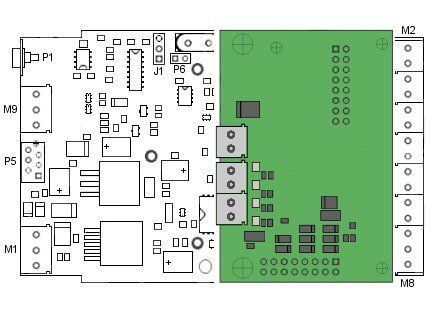
BieneRemote128GM Data Sheet

Hardware

The BieneRemote128GM module consists of the microprocessor, voltage regulator, inputs and outputs
drivers, relay, built-in GSM modem with SIM-card holder, GSM antenna connector and connectors for
external power supply and for input and output signals from external equipment connection.

                                                                                           -

                                                 5
BieneRemote128GM Data Sheet
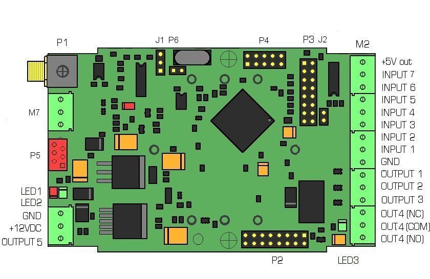
Connectors
• Screw terminal block for power supply connection (M1)
• Screw terminal blocks for Inputs and Outputs connection (M2...M6)
• 2x8 pin header for analog inputs connection (P2)
• SMA female connector for GSM antenna connection (P1)
• Serial Port RS232 (P5)
Power Supply
• On-board voltage regulation
• Reverse-polarity protection
• Required Power supply: external power supply +12VDC/2A stabilized (2A peak)
Antenna
• External GSM (900/1900 or 900/1800/1900 or 850/900/1800/1900) antenna with SMA male
connector
SIM Card
• Small SIM-card with 3V technology
LED indicators
• Module status indication - RED LED (LED1)
• GSM Modem status indication - GREEN LED (LED2)
• Relay output indication - GREEN LED (LED3)
Module LED indication (Red LED)
LED status Modem status
Permanently off Device off
Short blinking after power on and after 2 min periodic blinking SIM card read process
Blinking Module in work
Permanently on Module work with modem
GSM Modem LED indication (Green LED)
LED status Modem status
Permanently off Device off
Fast blinking (period 1s, ton 0,5s) Net search / Not registered / Turning off
Slow blinking (period 3s, ton 0,3s) Registered full service
Permanently on A call is active
6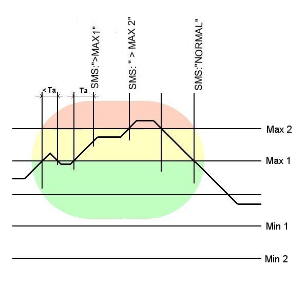
BieneRemote128GM Data Sheet

   Installation

Preparation of SIM card
   1. Delete any SMS messages from SIM.
   2. Disable PIN code request so it will not prompt for a PIN code on turning on.
   3. Write 7 authorized numbers to Phone Book (location 1,2,3…7) or write 999 to location 1 in SIM
      phone book (all numbers enabled)

   Note:
   1. The BieneRemote128GM can only be used with small SIM-cards with 3V technology.
   2. For SIM card preparation you can use cell phone or external GSM modem.
   3. SIM card change if power turn off.

External devices connection
   1.   Screw terminal blocks (M1) - for power supply connection
   2.   Screw terminal blocks (M2-M6) - for controlled equipment inputs and outputs connection
   3.   2x8 pin header (P2) - for analog signals connection
   4.   SMA female connector (P1) - for GSM antenna connection

                                                  7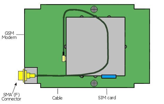
BieneRemote128GM Data Sheet

Power Supply Connection

+12VDC stabilized Power Supply must be connected with screw terminal block.
We recommend use stabilized +12VDC/2A power supply (2A peak).
Power supply input has negative voltage and over voltage protection.

Antenna connection

External GSM antenna must be connected to SMA connector (P1).
Use only the 50Om antenna of the necessary frequency range: 900/1800Mhz or 900/1900Mhz or tree
band antenna (900/1800/1900) or four-band antenna (850/900/1800/1900).

Note: It is very important that the antenna is installed on a location where the GSM-network coverage is
sufficient. Please also check carefully that antennas are not installed nearby technical devices, cables etc
which could influence the GSM-radiation.

                                                     8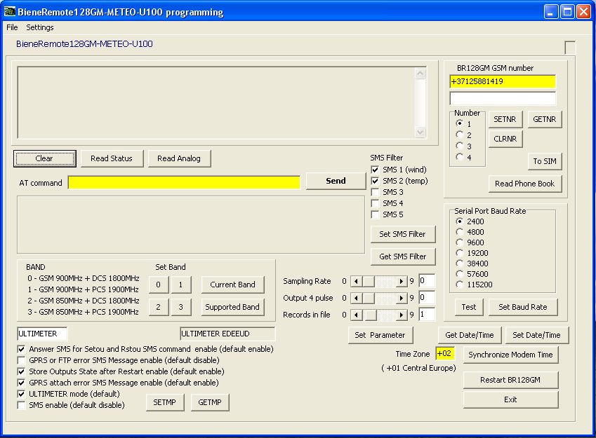
BieneRemote128GM Data Sheet

Inputs and Outputs connection

Digital inputs and outputs must be connected with screw terminals blocks.
Analog inputs must be connected with IDC16 flat cable connector.
Module has:
1. Transistor inputs
2. NO/NC relay output
3. MOSFET Open Drain outputs

Note: See also "Inputs and Outputs schematic".

Screw terminal blocs for Inputs and Outputs connection:

                    Function                                 Description
   1          +5V(output, 50mA max)
   2            INPUT 7 (optional)                     Digital Transistor Input
   3                INPUT 6                            Digital Transistor Input
   4                INPUT 5                            Digital Transistor Input
   5                INPUT 4                            Digital Transistor Input
   6                INPUT 3                            Digital Transistor Input
   7                INPUT 2                            Digital Transistor Input
   8                INPUT 1                            Digital Transistor Input
   9                  GND                                       GND
  10               OUTPUT 1                              Open Drain Output
  11               OUTPUT 2                              Open Drain Output
  12               OUTPUT 3                              Open Drain Output
  13               OUTPUT 4                               Relay Output NC
  14               OUTPUT 4                            Relay Output Common
  15               OUTPUT 4                              Relay Output NO

                                                   9
BieneRemote128GM Data Sheet
2x8 pin header (P2) for analog inputs connection
Pin Function
1 AVCC (+5V, 50mA max) Output
2 AREF Output
3 Analog Input 1 Input
4 Analog Input 2 Input
5
6 GND
7
8 GND
Note:
Microcontroller inputs not protected !
see " Microcontroller Inputs and Outputs Electrical Characteristics"
Serial Port
RS232 Serial Port
RS232 serial port used for direct PC serial port connection for module programming or monitoring.
RTS and CTS signals not used in this application.
J1 - select RS232-RS485
- select RS232
1BieneRemote128GM Data Sheet
Wather Station connection and jumper installation
Weather Station ULTIMETER 100 you can connected with serial cable to serial cable of ULTIMETER
100 (DB9 connector). Baud rate 2400 baud.
BieneRemote-WS include two Serial Cable
Serial Cable 1 – for PC connection (in programming/setting mode)
Serial Cable 2 – for ULTIMETER connection.
You can set two work mode:
programming/setting mode (you can connect to serial port Serial Cable 1 for from PC software
programming/setting)
work mode (to serial port with Serial Cable 2 connected ULTIMETER weather station)
Programming mode
P2 pin header
1BieneRemote128GM Data Sheet
Input and Output Schematic
Inputs
0-5V Analog Inputs
Connector: Pin Header P2
Input type: CMOS
Input Voltage: 0 to VCC (+5V)
Max input voltage: -0.5V...VCC+0.5V
Protection: No
Input resistance: 100 Mom typ.
ADC resolution: 10-bit
Digital Transistor Inputs
Connector: Screw terminal blocks M3, M4, M5
Inversion: yes
Protection: 2.7kOm serial resistor
Max input voltage: +12V without external limited resistor.
Free Input: logic "0"
Logic "0": 0V…+1V
Logic "1": +1.5V…+12V
1BieneRemote128GM Data Sheet
Outputs
MOSFET Open Drain Outputs
Connector: Screw terminal blocks M6, M7, M1
MOSFET transistor: STM STT5NF20V
Max. Voltage: 20V
Relay Outputs
Connector: Screw terminal blocks M7, M8
Outputs: NC (normal closed), NO (normal open), COM (common)
Relay: Tyco OEG TSC112, Omron G5V-1-12VDC or equivalent
Max. Voltage: 24VDC/1A; 120VAC/0.5A
Microcontroller Inputs and Outputs Electrical Characteristics
Absolute Maximum Ratings
Voltage on any Microcontroller Pin with respect to Ground: -0.5V to VCC+0.5V
DC Current per I/O Pin: 40 mA
DC Characteristics
Input Low Voltage: -0.5V to 0.2VCC
Input High Voltage: 0.6VCC to VCC+0.5V
Output Low Voltage: 0.7V max (20mA)
Output High Voltage: 4.2V min (20mA)
1BieneRemote128GM Data Sheet
Microcontroller Input protection
Supply Voltages Partially Switched Off
If BieneRemote module power supplies switched Off and connected sensors power supplies in On state,
use current limiting resistors for microcontroller inputs and outputs protection.
For over current protection can use current limiting resistor. For over voltage protection can use diode.
Microcontroller Digital Inputs Protection
Note:
Not use microcontroller pin for digital signal connection. Use digital transistor inputs for digital signal
connection. Digital transistor input connected to screw terminal blocks and also has serial resistor for
protection.
1BieneRemote128GM Data Sheet
Microcontroller Analog Inputs Protection
Note:
If you use microcontroller inputs for analog signal connection, use one of protection schematic.
We recommended used Analog Adapter Board with analog signal protection and with screw terminal
block. See "Analog Adapter Board #4A" or "Temperature & Analog Adapter Board #PT1000".
1BieneRemote128GM Data Sheet
Connection Example
Connection example to Input Driver (Input 1-6 on terminal block)
Relay connection example to Output Driver (Output 1, 2 and 3 on terminal block)
Electromechanical relay and Solid-state-relay (SSR) connection.
1BieneRemote128GM Data Sheet
Analog Adapter Board #4A
Analog Adapter Board used for connection BieneRemote128GM-METEO module with up to two 0-16V
analog signals.(input 1 for Battery Output connection – battery voltage level control)
Adapter has screw terminal blocks for analog signal connection. Each input has diode protection.
This board has schematic for 0…+16V (+5V reference) analog signal connection with diode protection.
-
Adapter has two 2x8 sockets P2 and P3 for insertion in P2 and P3 2x8
pin header on BieneRemote128GM.
BieneRemote128GM with Analog adapter board connection show on
figure below.
1BieneRemote128GM Data Sheet
BieneRemote128GM with inserted Analog Adapter Board #4A
Analog input schematic:
Diode and serial resistor used for microcontroller analog input protection.
Input analog signal divide to 2.
BieneRemote16 and BieneRemote128 analog signal measurement.
Reference set to +5V.
0-10V: 0V – 0%; 12V – 75%; 16V – 99%
1BieneRemote128GM Data Sheet
Module programming
For module programming:
1. SIM card preparation
2. Programming with send control SMS (see paragraph 'SMS Control Command List')
or via RS232 serial cable with software on PC (see " Programming software ").
SIM card preparation
1. Delete any SMS messages from SIM.
2. Disable PIN code request so it will not prompt for a PIN code on turning on.
3. Write 4 authorized numbers to Phone Book (position 1,2,3,4)
Note:
1. The BieneRemote128GM can only be used with small SIM-cards with 3V technology.
2. For SIM card preparation you can use cell phone or external GSM modem.
Programming with SMS
See " SMS Control Command List "
Module work without programming. But if you will use data logger function, you can set GPRS and FTP
setting. As optional you can use alarm SMS function and output control with SMS from your cell phone
1. Send SMS SETNR1 from your cell phone to BieneRemote128GM (store your number)
Setnr2 - for send SMS to two cell phone ...
2. You can set analog signal level
Programming via serial port
See " BieneRemote128GM-METEO setting up software "
1BieneRemote128GM Data Sheet
Alarm SMS message in SIM card
Set phone numbers from which management is authorized (number in SIM phone book)
Phone Book
1 A1 1)
2 A2 1)
3 A3 1)
4 A4 1)
Note 1: full phone number with country code
Example - enable 3 phone numbers for BieneRemote management
Phone Book
1 A1 +3719106159
2 A2 +3716149759
3 A3 +3718398597
Example - enable all phone numbers (disable authorization numbers)
Phone Book
1 A1 99
2 A2
Outgoing numbers memory
You can send SMS command Setnr1 from first cell phone.
You can send SMS command Setnr2 from second cell phone.
...
You can send SMS command Setnn1 [number] from your cell phone; where number = full cell phone
number with international code (for example, +37129106159).
Cell phone / GSM modem / BR module
Nr.1 Phone number Nr.1
Nr.2 Phone number Nr.2
Nr.3 Phone number Nr.3
Nr.4 Phone number Nr.4
2BieneRemote128GM Data Sheet
SMS text memory
Write with SMS command Settx and Setti or via serial port.
position SMS text message
External (up to 32 character)
01 Digital input 1 0-1 events
02 Digital input 2 0-1 events
03 Digital input 3 0-1 events
04 Digital input 4 0-1 events
05
06
07
08 Digital input 1 1-0 events
09 Digital input 2 1-0 events
10 Digital input 3 1-0 events
11 Digital input 4 1-0 events
12
13
14
15 BATTERY VOLTAGE VERY LOW
16 BATTERY VOLTAGE LOW
17 BATTERY NORMAL
18
19
20 Analog input 2 minimum 2 level
21 Analog input 2 minimum 1 level
22 Analog input 2 normal
23 Analog input 2 maximum 1 level
24 Analog input 2 maximum 2 level
Outgoing numbers
Cell phone
Nr.1 Phone number Nr.1
Nr.2 Phone number Nr.2
Nr.3 Phone number Nr.3
Nr.4 Phone number Nr.4
2BieneRemote128GM Data Sheet
Digital and analog signal monitoring
Digital signal monitoring (0-1 and 1-0 events)
You can set different SMS notification message for 0-1 and for 1-0 events.
For example, 0-1 SMS message 'DOOR OPEN', 1-0 SMS message 'DOOR CLOSE'.
Analog signal monitoring
Can set 2 minimum level and 2 maximum level:
MINIMUM 2 < MINIMUM 1, MAXIMUM 2 > MAXIMUM 1
For analog signal monitoring
MINIMUM1 and MAXIMUM1 level.
MINIMUM2 and MAXIMUM2 level.
2BieneRemote128GM Data Sheet
SMS Control Command List
Command 1) Function Return Message Description
METEO DATA
ULTIMETER
Getmet Get weather report WEATHER Request weather report.
REPORT text
ULTIMETER
Getmt Get weather report WEATHER Request weather report.
REPORT text
DIGITAL
INP= 0001
OUT=00000 Get input state , output state, Output 4
Ref=+5V T4=0 pulse parameter (see Settn), Sample Rate
Get Technical
Getst SR=5 BL=4 SQ: (see Settn), Block length (see Settn),
Status
27,7 SMS: Enable Alarm enable/disable, signal quality,
Baud Rate: 2400 Baude Rate (const) SMS filter
SMS filter: 11000
Setou1 Set Output 1 Technical Status Set Output 1
Setou2 Set Output 2 Technical Status Set Output 2
Setou3 Set Output 3 Technical Status Set Output 3
Setou4 Set Output 4 Technical Status Set Output 4 - relay ON
Setou5 Set Output 5 Technical Status Set Output 5
Rstou1 Reset Output 1 Technical Status Reset Output 1
Rstou2 Reset Output 2 Technical Status Reset Output 2
Rstou3 Reset Output 3 Technical Status Reset Output 3
Rstou4 Reset Output 4 Technical Status Reset Output 4 - relay OFF
Rstou5 Reset Output 5 Technical Status Reset Output 5
Set Sample Rate (0 – disable data logger,
Data logger sample
1 – 1min, 2 – 2min, 3 - 3min, 4 - 4min, 5 -
rate (0..9); Output 4
5min, 6 - 10min, 7 – 15min, 8 – 20min, 9
impulse duration
SettnD U L Technical Status – 30 min); default – 1.
(0..9 = 0..18 sec);
Set Output 4 pulse duration = 2*U sec;
L records in data
default – 0 (no pulse):
logger file (1,2,4,8)
L - records in data logger file; default - 4
COMMON
Seten Alarm SMS enable Technical Status Set active mode - Alarm SMS enable
Setdi Alarm SMS disable Technical Status Set passive mode - Alarm SMS disable
Rstrt Restart Module Restart Module
TEXT
Write alarm SMS Write alarm SMS text; NN =
SettxNN [text] text (external) NN-[text] 01,02,03,..24
{text] up to 32 characters
Read alarm SMS
Read alarm SMS text; NN = 01,02,03,..24
GettxNN text (external) NN-[text]
{text] up to 32 characters
OTHER SETTING
MP: ULTIMETER
Setmp ULTIMETER EDEDUE Set other setting
EDEDUE
MP: ULTIMETER
Getmp
EDEDUE
2BieneRemote128GM Data Sheet
Command Function Return Message Description
ANALOG
Get analog data (in %) and
A1=0 A2=0 / level (min2, min1, max1,
A1:10 20 80 80 A2:00 00 00 00 max2) for 2 analog inputs
Getan Get Analog Data
T1=21 T2=22 Temperature in "C
BATTERY 12,4 V Battery voltage level (analog
input 1)
Max Level 1 > 5
A1=00 A2=00
Set level for Max Level 2 > 10
A1:00 00 00 00 A2: 00 00 00 00
AnlevN 00 00 00 00 analog input N, if Max Level = 0 and Min
T1=21 T2=22
2) Level = 0, then no alarm SMS
BATTERY 12,4 V
message
Set Baud Rate for serial port
Set Baud Rate;
Setbr B Baud Rate: 2400 (after command – restart
B = 1...7 (optional)
module)
Set meteo SMS filter
Setsf 10000 Set SMS filter SMS filter 10000
10000 – send only first SMS
11000 – send two SMS
Getsf Get SMS filter SMS filter 10000
11111 – send all SMS
NUMBERS
Set cell phone for alarm
Set number notification
SetnrN Technical Status
N=1,2,3,..,7 Send this SMS from cell phone
for alarm notification
Clear number Clear cell phone for alarm
ClrnrN Technical Status
N=1,2,3,..,7 notification
Read number Read stored notification
GetnrN +3715881456
N=1,2,3,..,7 numbers
N1:99 N2:+3716149759
Read administration numbers
N3:+3715881419
Getpb Read phone book (first 7 numbers from SIM
N4:+3715881456
phone book)
N5:+3715875473 N6: N7:
OTHER SETTING
Setmp ULTIMETER EDEEUD Set various setting MP: ULTIMETER EDEEUD ULTIMETER – start text
E - Answer Enable
D - GPRS error SMS Enable1
E – Store Output Enable:
Getmp D – GPRS error SMS Enable2
U – Ultimeter Mode
E – SMS Enable Flag
Note 1) Not case sensitive. You can use GETST, Getst,
Note 2) If Max analog level = 00, then alarm for this level disable
If Min analog level = 00, then alarm for this level disable
2BieneRemote128GM Data Sheet
GPRS/FTP setting up
Command Function Return Message Description
GPRS
Setap [APN] - APN - Access Point Name;
Setap [APN] Set APN or
APN: [APN] without APN - disable Data Logging to GPRS
Setap disable GPRS
(only SMS mode)
Getap Get APN APN: [APN] Get Access Point Name
Set IP address (GPRS context);
Setip [IP address] Set IP address IP address: 0,0,0,0
0,0,0,0 means dynamic
Getip Get IP address IP address: 0,0,0,0 Get IP address (GPRS context)
Setid [User ID] Set User ID User ID: [user ID] Authentication setting
Getid Get User ID User ID: [user ID] Authentication setting
Setpw [ Password] Set Password PASSWORD: [password] Authentication setting
Getpw Get Password PASSWORD: [password] Authentication setting
FTP
Setft [URL] Set URL FTPURL: [URL] Set URL address of FTP server
Getft Get URL FTPURL: [URL] Get URL address of FTP server
Setaf (User Name] Set User Name UserName FTP: [User Name] Set User Name
Getaf Get User Name UserName FTP: [User Name] Get User Name
Set authentication password for FTP.
Setpf [“Password”,0] Password FTP: [“password”,0]
Password in “ ”. After password can set ,1
or Set Password or
Setpf [“Password”,1] Password FTP: [“password”,1] if the ftp-server needs a passive transfer.
Default – active transfer.
Getpf Get Password Password FTP: [password] Get authentication password for FTP
Setnm [User Name] Set User Name User Name: [user name] Set authentication user name
Getnm Get User Name User Name: [user name] Get authentication user name
SETTING UP GPRS Internet
APN (Access Point Name) - the logical name that selects the GGSN network connected
4. for example:
5. for LMT (Latvia) - internet or internet.lmt.lv
6. for Orange - orangeinternet
7. for Vodafone - internet
User ID and Password - authentication setting
Username and password may be are not required for Internet access
IP address - is the IP address associated with the terminal in the address space of the PDP.
IP address is assigned dynamically, or you can use a static IP address
SETTING UP FTP
URL - address of FTP server (for Data Logging files *.csv)
User Name - authentication user identification string for FTP
Password - authentication password for FTP. Password in “ ”. After password can set ,0 if the ftp-
server needs a passive transfer, 1 – if passive transfer. Default – passive transfer.
For example:
“123”,1 if FTP server needs a passive transfer (recommend)
2BieneRemote128GM Data Sheet
Output state (default)
Output state
Output state
on terminal block
(on microcontroller)
(BieneRemote16)
Output 1 0 1
Output 2 0 1
Output 3 0 1
Output 4 0 1 relay
Output 5 0 1
Not connected input state
Input state Input state on
(on microcontroller) terminal blocks
Input 1 1 0
Input 2 1 0
Input 3 1 0
Input 4 1 0
Active event on input
Input state on
Input state
terminal blocks
Input 1 0-1 1-0 1-0 0-1
Input 2 0-1 1-0 1-0 0-1
Input 3 0-1 1-0 1-0 0-1
Input 4 0-1 1-0 1-0 0-1
2BieneRemote128GM Data Sheet
BieneRemote128GM-METEO-U100 setting up software
With BR128GM-METEO.exe software and serial port cable you can:
setting up or testing BR128GM-METEO-U100 module:
change parameter (SMS text message, analog level), check default setting,
set band (GSM900/1800 or GSM900/1900 or GSM 850/1800 or GSM850/1900);
set cell phone numbers or other BieneRemote module numbers;
setting up GPRS and FTP parameter for data logging process via GPRS.
Baud Rate for communication with BR128GM module - 2400 Baud.
Set programming mode
P2 pin header
SETTING UP PROCESS
1. Turn Off computer
2. Connect BR128GM and computer with serial cable
3. Turn On computer
4. Run BR128GM-Pt1000 / -4A setting up software
5. Power On BR128GM
6. Wait message " Welcome to BR128GM-METEO-U100 programming"
7. You can programming BR128GM-METEO-U100 module
Serial port settings
SETTING UP SERIAL PORT
Baud Rate = 19200
2BieneRemote128GM Data Sheet
Main windows
Menu
Setting,
External SMS message,
Analog Setting,
GPRS/FTP setting,
Serial port setting,
Save setting
BAND
0,1,2,3 - GSM band setting up.
0 - GSM 900/1800 - for EUROPE, AFRICA, ASIA
1 - GSM 900/1900; 2: GSM 850/1800
3 - GSM 850/1900 - USA, CANADA, SOUTH and CENTRAL AMERICA
2BieneRemote128GM Data Sheet
NUMBERS
Yellow: BR128GM number - remoted BR128GM module cell phone number
White: number for SETNR command (as Setnn SMS command)
Number (1..4), SETNR, CLRNR, GETNR - set, clear, get numbers to/from
BR128GM.
To SIM – set number to SIM phone book
Read Phone Book – Read from SIM phone book
SET TIMEOUT
(Button SET PARAMETER - as SMS command Settn)
Set Output 4 pulse duration; if 0 – no pulse.
Set data logger sample rate; if 1 – 1 min; 2 – 2min; 3 – 3min; 4 –
4min; 5 – 5min; 6 – 10min; 7 – 15min; 8 – 20min; 9 - 30min
Set Data Logger Period; if 0 or 1 – 1 record in file, 2 – 2 records in
file, 4 – 4 records in file, 8 – 8 records in file.
AT COMMAND
You can direct execute AT command (not all) to Telit GM862 GSM/GPRS modem
VARIOUS SETTING
ULTIMETER - text identificator
Answer SMS for SMS command Setou, Rstou; if enable, you receive answer from module; default – disable
GPRS or FTP error SMS message; if enable, you receive SMS, if FTP or GPRS error
Store Output State; if enable, after restart module outputs stored state before restart
GPRS attach error message; if enable, you receive SMS if GPRS attach error
ULTIMETER mode – enable for ULTIMETER version (default)
SMS enable (only for not ULTIMETER mode)
Set Date/Time button - set Date/Time (from PC date/time)
Get Date/Time button - get Date/Time
Synchronize Modem Time - not used in programming mode.
2BieneRemote128GM Data Sheet
SET ALARM TEXT SMS
SET ANALOG LEVEL
3BieneRemote128GM Data Sheet
GPRS/FTP SETTING
SETTING UP GPRS/FTP
APN (Access Point Name) - the logical name that selects the GGSN network connected
8. for example:
9. for LMT (Latvia) - internet or internet.lmt.lv
10. for Orange - orangeinternet
11. for Vodafone - internet
User ID and Password - authentication setting
Username and password may be are not required for Internet access
IP address - is the IP address associated with the terminal in the address space of the PDP.
IP address is assigned dynamically, or you can use a static IP address
Note: If APN if blank, GPRS mode disable
SETTING UP FTP
URL - address of FTP server (for Data Logging files *.csv)
User Name - authentication user identification string for FTP
Password - authentication password for FTP – in “”
3BieneRemote128GM Data Sheet
Mechanical Specification
BieneRemote128GM PCB size:
3You can also read