Potential Launch Opportunities for a SmallSat Mission around the Moon Injected during a Lunar Flyby En Route to Mars
←
→
Page content transcription
If your browser does not render page correctly, please read the page content below
Hindawi
Mathematical Problems in Engineering
Volume 2019, Article ID 1245213, 14 pages
https://doi.org/10.1155/2019/1245213

Research Article
Potential Launch Opportunities for a SmallSat Mission around the
Moon Injected during a Lunar Flyby En Route to Mars

 Yongjun Song ,1 Young-Joo Song ,2 Seongwhan Lee ,1 Kap-Sung Kim,1 and Ho Jin 1

 1
 School of Space Research, Kyung Hee University, Yongin 17104, Republic of Korea
 2
 Lunar Exploration Program Office, Korea Aerospace Research Institute, Daejeon 34133, Republic of Korea

 Correspondence should be addressed to Young-Joo Song; dear.yjsong@gmail.com

 Received 2 May 2019; Revised 18 August 2019; Accepted 31 August 2019; Published 24 September 2019

 Academic Editor: Florin Stoican

 Copyright © 2019 Yongjun Song et al. This is an open access article distributed under the Creative Commons Attribution License,
 which permits unrestricted use, distribution, and reproduction in any medium, provided the original work is properly cited.
 In this work, the concept of a multipurpose mission that can explore both the Moon and Mars with a single launch is proposed,
 and potential launch opportunities are analyzed to establish an early-phase trajectory concept. The proposed mission applies the
 concept of a piggyback ride to a small-sized lunar probe, i.e., the daughtership, of the main Mars orbiter, i.e., the mothership. For
 the trajectory design, the Earth-Moon-Mars gravity assist (EMMGA) trajectory is adopted for the mothership to reach Mars, and
 the daughtership is assumed to be released from the mothership during lunar flyby. To investigate the early-phase feasibility of the
 proposed mission, the launch windows have been analyzed and the associated delta-Vs have been directly compared with the
 solutions obtained for typical Earth-Mars direct (EMD) transfer options. The identified launch windows (in the years 2031 and
 2045) could be the strongest candidates for the proposed conceptual mission. Under the current assumptions, up to approximately
 15% (in 2031) and 9% (in 2045), more dry mass is expected to be delivered to Mars by appropriately selecting one of the currently
 available launch vehicles, regardless of whether the EMMGA transfer option is used. For missions around the Moon using a
 SmallSat in 2031, the feasibility of a lunar orbiter case and an impactor case is briefly analyzed based on the delta-Vs required to
 divert the SmallSat from the mothership. Although the current work is performed under numerous assumptions for a simplified
 problem, the narrowed candidate launch window from the current work represents a good starting point for more detailed
 trajectory design optimization and analysis to realize the proposed conceptual mission.

1. Introduction conducted on orbital stabilities and low-energy transfers
 [4–12]. Further details on the relevant literature are left for
For many scientific reasons, interest in interplanetary ex- the readers to discover, as there exists a significant amount of
ploration for scientific discovery purposes is currently rising. research.
The National Aeronautics and Space Administration Also of interest when designing interplanetary missions
(NASA) announced its goal of a human exploration mission is the reduction of the overall mission cost while reliably
to Mars and is first focusing on the return of humans to the achieving the original scientific and technological mission
surface of the Moon. As a part of this plan, NASA will objectives. In general, the total mission costs for in-
construct a lunar orbital platform called the Gateway, which terplanetary missions can be reduced by using a number of
is a modular space station located in near rectilinear halo approaches, such as by minimizing the required overall
orbit (NRHO) between the Earth and the Moon [1]. The delta-Vs to accomplish the mission, by designing the mis-
Gateway will serve as the gateway for lunar landing and sion trajectory to target multiple planets within a single
further deep space missions [2]. By utilizing the Gateway, launch, or by designing missions that can be performed with
NASA plans to land the first female astronaut on the Moon a small-sized spacecraft.
by 2024 and aims to establish a sustainable human presence Most of the launch windows for interplanetary missions
on the Moon by 2028 [3]. As the paradigm for planetary are usually designed to minimize the required delta-Vs, and
exploration has shifted, many fascinating studies have been the flyby technique is occasionally applied to reduce the
2 Mathematical Problems in Engineering

overall mission cost. A flyby, which is a gravity-assisted payload gain. Kawaguchi et al. [25] designed a real Earth-
flight, utilizes the gravity of a celestial body to change the Mars trajectory for the Japanese Mars exploration spacecraft,
spacecraft’s direction or speed, thus allowing the spacecraft NOZOMI, using a similar double lunar flyby method.
to gain or lose energy without any additional fuel con- Hernandez and Barbee [26] considered using a single lunar
sumption. The flyby technique can be adapted to design flyby for the Near-Earth Asteroids (NEA) mission, and their
transfer trajectories between other planets or central body main objective when adapting lunar flybys to explore NEA
bounding trajectories directed toward another planet by was to reduce the total required delta-Vs during the overall
using the natural moon [13]. This flyby technique has en- mission sequences. They concluded that a lunar flyby is more
abled interplanetary missions requiring high inclination effective than a direct transfer for exploring NEA. All these
changes relative to the ecliptic plane with limited perfor- studies concluded that lunar flyby methods allow a space-
mance of the launch vehicle [14]. Moreover, by applying the craft to depart Earth at a lower energy than that needed to
flyby technique, not only can delta-V budgets be minimized, escape and then proceed to planetary encounters. Although
but the opportunity to visit additional planets in a single many studies apply the concept of lunar flyby to design Earth
launch can be gained. This concept is called a multipurpose escape trajectories, most of these studies applied multiple
space mission because it allows for the exploration of several lunar gravity assists to maximize delta-V savings. Similar
targets in a single mission [15]. work was conducted by Hanson et al. [24] in the 1990s. In
 In addition to minimizing overall mission costs by Ref. [24], many lunar flyby options were considered, but
finding the best launch windows, either for direct or flyby multiple lunar gravity assists were focused on rather than a
missions, the overall mission costs and riskiness will be single flyby to reduce the delta-V budget. The application of
greatly reduced if interplanetary missions are performed multiple lunar gravity will lead to very complex mission
with a small-sized spacecraft. With current technological operations, which have already been discussed as a disad-
improvements, diverse scientific data can be collected at an vantage of the multiple gravity assist [24]. Furthermore,
extremely low cost if a small-sized spacecraft is used for solar feasibility studies on Mars transfer trajectory design with a
system exploration missions [16]. Indeed, the NASA In- single lunar flyby have rarely been performed. Most im-
novative Advanced Concepts Program (NIAC) has planned portantly, no recent work has proposed and analyzed
small, low-cost missions beyond the low Earth orbit using possible Mars mission launch opportunities using single
CubeSats [17]. Additionally, the first Mars exploration lunar flyby for the upcoming decades. Providing such future
CubeSat, MarCO (Mars Cube One), was launched with a launch opportunities is very important in further realizing
Mars lander called InSight on May 2018, and it sent an image the proposed conceptual mission. Therefore, the current
from Mars [18]. Moreover, conceptual CubeSat missions for work investigates suitable launch opportunities of a Mars
other solar system objects, such as Io [19] and Deep Space mission by using only a single lunar flyby to support the
Gateway (DSG) [20], have been proposed recently. emerging SmallSat piggyback ride planetary mission con-
 One of the most important concerns during the early cept. Utilization of single lunar flyby will ultimately ease the
design stage of a Mars mission is finding a solution that can mission operation and minimize overall mission riskiness,
reduce the overall mission cost while maximizing the sci- which will be a driving factor of mission success.
entific and technological gains. One of the solutions could be The main objective of the current study is to perform an
building a mothership that can carry a small satellite as an early-phase feasibility study on a proposed conceptual
onboard payload to achieve a lunar flyby en route to Mars, multipurpose mission. The realization of such a mission first
which certainly will provide additional opportunities to requires trajectory design studies that estimate the overall
explore the Moon with a single launch. During the moth- mission delta-V budgets. The current study investigates
ership’s lunar flyby phase, a small satellite could be released launch opportunities for an Earth-Mars mission utilizing a
to orbit the Moon and perform its own mission to achieve its flyby of the Moon, and it includes an estimation of the
designated scientific goals. After the release of a small sat- required overall delta-V budgets. For the first step, to
ellite, the mothership continues its journey to Mars to ac- roughly estimate overall mission delta-V budgets, the cur-
complish its main mission objectives. This concept also rent work employed a simplified methodology, the patched
benefits the system reliability of a small satellite’s bus conic method with simplified equations of motion, to de-
compared with an interplanetary mission planned with only termine potential launch years. The obtained delta-V bud-
the small satellite itself because a small satellite’s bus can be gets are compared with typical delta-V values obtained using
effectively protected from planetary hazards, such as thermal Earth-Mars direct transfer options. The mothership’s mass
and radiation hazards, during the journey to the Moon budget characteristics are also roughly investigated using
[21, 22]. currently available data on heavy launch vehicle perfor-
 Many authors have revealed the usefulness of utilizing a mance. Additionally, the mass budgets for a SmallSat mis-
lunar flyby when designing an interplanetary mission. sion around the Moon deployed from a mothership were
Farquhar and Dunham [23] reported that double lunar estimated. Although the current work utilized well-known
swingby maneuvers increase the C3 value from –0.5 to methodologies to derive results, it is expected that the
4.5 km2/s2 and suggested that double and triple lunar flybys current work can make the following contributions: First,
could potentially offer trips to the planets. Hanson et al. [24] both mission designers and supervisors who are interested in
analyzed the potential of an Earth-Mars trajectory by using SmallSat application to interplanetary missions can gain
single and multiple lunar flybys to improve the available insight while establishing similar mission concepts. Second,

Mathematical Problems in Engineering 3

the current work can serve as a reference for further work increase the maturity of the trajectory solutions obtained
related to launch opportunities in the near future. Finally, through this work, and these equations can be used as a basis
based on the results of the current work, detailed trajectory of further work regarding the detailed optimization of high-
design solutions can be advanced by implementing an op- fidelity dynamic models. The equations of motion of the
timization algorithm with N-body equations of motion and mothership with Earth as the primary central body and the
with more realistic mission constraint parameters. The re- Moon and Sun as perturbing bodies in the Earth-centered
mainder of this manuscript is organized as follows: Detailed Earth mean equator and equinox of epoch J2000 (E-
simulation procedures, including equations of motion based EME2000) coordinate system are expressed in [28, 29]:
on the patched conic method, are described in Section 2. The
 r_ E− SC � vE− SC , (1a)
numerical implications and assumptions for setting up the
simulation are provided in Section 3. Detailed simulation μ
results and an associated discussion are presented in Section v_ E− SC � − E 3 rE− SC + gE− L + gE− S , (1b)
 r_ E− SC
4. The conclusions are discussed in Section 5.
 where rE− SC , vE− SC , and r_ E− SC denote the position, velocity,
2. Models and Methods and acceleration vectors of the mothership with respect to
This section describes the models and methods used to design the Earth, respectively, μE is the gravitational constant of the
an Earth-Moon-Mars gravity assist (EMMGA) trajectory and Earth, and gE− L and gE− S are the perturbing gravitational
determine the orbit of a lunar SmallSat. In this paper, we use a forces of the Moon and Sun with Battin’s q function, re-
single lunar flyby method similar to that described by Her- spectively, which can be expressed as follows [28, 30]:
nandez and Barbee [26] to calculate the EMMGA trajectory. μ
 gE− L � − L 3 rE− SC + F qL rE− L , (2a)
The EMMGA trajectory is designed using the patched conic rL− SC
method. This method uses a series of conic sections patched
together to form a trajectory bounded by the central body, μ
which primarily affects the motion of the spacecraft. For a gE− S � − s 3 rE− SC + F qs rE− S , (2b)
 rS− SC
detailed discussion of this method, readers can refer to the
papers by Barbee et al. [27] and Hernandez and Barbee [26]. where μL and μS are the gravitational constants of the Moon
In this method, the EMMGA trajectory is divided into three and Sun, respectively, and rL− SC and rS− SC are the position
phases: Earth-centered, Sun-centered and Mars-centered. In vectors from the Moon and Sun to the mothership, re-
the Earth-centered phase, the mothership releases the spectively. The q functions for the Moon, F(qL ), and the Sun,
SmallSat during the lunar flyby phase, and the released F(qS ), are expressed as follows:
SmallSat is then captured by the Moon with an onboard
thruster. After the flyby, the mothership is ejected to an Earth- 3 + 3qL + q2L ⎥⎥⎤
escape hyperbola that leads to Mars after a Sun-centered F qL � qL ⎢⎢⎣⎡ ����� 3 ⎦, (3a)
 1 + 1 + qL
interplanetary cruise phase. During the Mars-centered phase,
the mothership arrives at the Mars sphere of influence and
enters the Mars parking orbit. To design the Earth’s sphere of rE− SC 2 − 2rE− SC · rL− SC
 qL � , (3b)
influence (SOI) escape trajectory, it is assumed that the rL− SC 2
mothership uses only a single, unpowered lunar gravity assist.
However, multiple lunar gravity assist techniques can be
 3 + 3qS + q2S ⎤⎥⎥
applied for this phase rather than a single flyby to reduce the F qS � qS ⎡⎢⎢⎣ ����� 3 ⎦, (3c)
delta-V budget. Indeed, reducing overall delta-V cost by 1 + 1 + qS
utilizing multiple gravity assist is another important factor
that should be considered during the early mission design
 rE− SC 2 − 2rE− SC · rS− SC
phase. However, as discussed, the current work is focused on qS � . (3d)
investigating suitable launch opportunities under a single rS− SC 2
lunar flyby. Lastly, the delta-Vs in the current work are as-
sumed to be impulsive burns during each phase. The initial conditions of equations (1a) and (1b) can be
 defined with the initial position (r0 ) and velocity vectors (v0 )
 of the mothership as follows:
2.1. Lunar Flyby Trajectory Generation En Route to Mars p
 r0 � rE− SC , (4a)
2.1.1. Earth-Centered Phase (Stage 1). The first step in de-
signing the trajectory consists of targeting a lunar flyby in the p
 v0 � vE− SC + ΔVDep , (4b)
Earth-centered phase. In this stage, the trajectory of the
 p p
mothership is designed using four-body equations of mo- where rE− SC and vE− SC are the position and velocity vectors of
tion. Four-body equations of motion can be replaced with the mothership on the initial Earth parking orbit, re-
two-body equations of motion in this Earth-centered phase spectively, and ΔVDep is defined as the delta-V vector re-
for preliminary trajectory design purposes. However, the quired to transfer the mothership to the Moon under four-
current work adopted four-body equations of motion to body dynamics.

4 Mathematical Problems in Engineering

 p p
 To derive rE− SC , vE− SC , and ΔVDep , the current work used Earth-Moon system is propagated with stopping conditions
Ramanan’s pseudostate method [31] and slight corrections for the mothership when it reaches the Earth’s SOI after a
were made to the obtained results for application in four- single lunar flyby over a time span of ttof_SOI . The radial
body dynamics. Ramanan’s method is a very powerful and distance of the Earth’s SOI, RSOI , is given as 924,500 km.
effective method based on two-body dynamics, and it solves When the trajectory reaches the Earth’s SOI after a lunar
Lambert problem iteratively to generate initial conditions of flyby, the mothership’s state vectors (rSOI and vSOI ) are
transfer trajectories for moon missions. Of course, the best located on the boundary of the Earth’s SOI at tSOI , which can
 p p
way to obtain rE− SC , vE− SC , and ΔVDep is to apply an opti- be simply calculated as tSOI � tTLI + ttof_SOI . During propa-
mization algorithm under a high-fidelity dynamic model. gation, two different constraints are used to ensure that the
However, the current work used Ramanan’s pseudostate generated trajectory is a lunar flyby. The first constraint is
method to focus on the preliminary analysis. To use Ram- given as h > 0 km, where h is the altitude of the mothership
anan’s pseudostate method, the user must first define the from the surface of the Moon. If h is less than 0 km during
following parameters: the translunar injection (TLI) ma- the simulation, then the mothership will impact the lunar
neuver time (tTLI ), the Earth-Moon transfer time (ttof_E− M ), surface. The second condition is a constraint, ttof_SOI . The
and initial Earth parking orbit elements (i.e., semimajor axis maximum of ttof_SOI is given as 20 days during the simu-
(ap ), eccentricity (ep ), inclination (ip ), and argument of the lation because the typical mothership’s flight time in the
perigee (ωp )). In addition, the user should select a preferred Earth’s SOI is approximately 10 days when a single lunar
TLI maneuver location. Usually, there are two possible flyby is applied. If the mothership cannot reach the Earth’s
maneuver execution locations on the initial parking orbit for SOI until a ttof_SOI of 20 days, then we consider that the
a given tTLI : one during the ascending motion of the parking mothership is unable to escape from the Earth’s SOI after
orbit and the other during the descending motion. Once flyby. If the trajectory does not satisfy one or both of these
these parameters are given, the Ramanan’s pseudostate constraints during propagation, then we assume that the
method can be used to calculate the remaining parking orbit EMMGA trajectory is impossible to be generated. Herein,
elements (i.e., the right ascension of the ascending node additional constraints should be considered to ensure a
(Ωp ), the true anomaly (υp ), and the minimum TLI ma- practical lunar flyby for real-flight operation. For instance,
neuver vector (ΔvTLI_2body ). For additional details on “face-on” geometry during lunar flyby should be guaranteed
Ramanan’s pseudostate method, refer to Ref. [31]. for the purpose of Earth communication, and lower limits on
 After applying Ramanan’s pseudostate method, the state flyby altitude and velocity should be set, as these conditions
 p
vectors of the mothership in the Earth parking orbit (rE− SC are strongly related not only to the mothership but also to
 p
and vE− SC ) and ΔvTLI_2body are obtained, where ΔvTLI_2body is SmallSat’s bus design, especially the fuel budget. Never-
the minimum TLI maneuver vector derived under two-body theless, the current work omits details of these additional
dynamics. As the current work used four-body equations of constraints, as they can be derived only after further es-
motion during the Earth-centered phase, ΔVDep , as shown in tablishment of detailed mission concepts and goals.
equations (4a) and (4b), cannot be directly replaced with
ΔvTLI_2body . Therefore, ΔVDep is obtained in relation to
ΔvTLI_2body , as follows: 2.1.2. Sun-Centered Phase (Stage 2). When the mothership
 escapes from the Earth’s SOI, the gravity of the Sun becomes
 ΔVDep � ΔvTLI_2body + ΔVadd , (5a)
 the dominant force. In this phase, the motion of the
 mothership is primarily affected by the Sun, and the per-
 ΔvTLI_2body turbations of other planetary bodies are neglected. To de-
 ΔVDep � ΔVDep × . (5b)
 ΔvTLI_2body scribe the motion of the mothership in the Sun-centered
 phase, the state vectors of the mothership are transformed
 As shown in equations (5a) and (5b), a small velocity into a heliocentric ecliptic coordinate system, thus pro-
magnitude correction, ΔVadd , is made to the magnitude of ducing the following equations:
ΔvTLI_2body while maintaining the same direction as that of
ΔvTLI_2body . The direction of ΔVDep will not actually be rSSOI � M tSOI rSOI + rSE , (6a)
exactly the same as that of ΔvTLI_2body , but the current work
accepted this assumption, as the delta-V magnitude change vSSOI � M tSOI vSOI + vSE , (6b)
rate plays a more significant role in the resultant trajectory
solutions than the direction change rates unless the esti- where rSOI and vSOI are the state vectors of the mothership
mated delta-V directions are completely insufficient. The with respect to the Earth, as previously discussed, rSSOI and
current work obtained proper ranges of ΔVadd based on trial vSSOI are the position and velocity vectors of the mothership
and error by investigating the behaviors of the resultant with respect to the Sun-centered frame, respectively, and rSE
trajectory. Within the given ranges of ΔVadd , ΔVadd that and vSE are the Earth’s state vectors with respect to the Sun,
minimizes ΔVDep while satisfying the lunar flyby condition which are calculated from the precise ephemerides. The
is selected as a candidate ΔVadd . matrix M(tSOI ) is the rotation matrix that converts the state
 After the initial state vectors required to perform a vector from equatorial coordinates to ecliptic coordinates
lunar flyby (r0 and v0 ) are determined, the trajectory of the at tSOI [32–34].

Mathematical Problems in Engineering 5

 After converting the states, the trajectory from the overall conceptual diagram of the mission segment through
Earth’s SOI to Mars’ SOI can be simply calculated via the stage 1–3 and the delta-V maneuver points is schematically
Lambert problem in the heliocentric coordinate system. To shown in Figure 1.
solve the Lambert problem, the previously calculated rSSOI ΔVTotal � ΔVDep + ΔVSOI + ΔVArr . (10)
and tSOI as well as the Mars arrival time (tArr ) and the Sun-
centered position of Mars (rSM ) at tArr are required. By
solving the Lambert problem, the required velocity at the
Earth’s SOI (vSDep_SOI ) and at Mars’ arrival (vSArr_M ) can be 2.2. Released SmallSat Trajectory Generation. The equations
easily calculated. Once the Lambert solution is found, the of motion of the SmallSat released from the mothership
required delta-V for leaving the Earth’s SOI, ΔVSOI , can be during lunar flyby are described with two-body motion as
simply calculated as follows: follows:

 ΔVSOI � vSDep_SOI − vSSOI . (7) μ
 r€L− SC � − L 3 rL− SC .
 rL− SC (11)
 The method adapted to compute ΔVSOI in the current
study is mainly used to adapt the patched conic method to In equation (11), r€L− SC and rL− SC represent the accel-
focus on the preliminary analysis. Notably, computing eration and position vectors of the SmallSat in the Moon-
delta-V at the SOI may not be efficient from an energetic Centered Moon mean equator and International Astro-
point of view, requiring further improvement through nomical Union (IAU) vector of the epoch J2000 (M-
optimization using N-body dynamics. For example, instead MME2000) coordinate system, respectively. Note that the
of imparting the delta-V at the moment of SOI crossing, the SmallSat is assumed to be released from the mothership at
following options can be considered in upcoming work. the moment of the mothership’s perilune passage (tp ) during
First, a powered lunar flyby that imparts the delta-V at the flyby. The value of tp can easily be computed during
moment just after periapsis passage of the Moon can be propagation of the mothership’s trajectory under the con-
considered. Imparting the delta-V just after periapsis seems dition of a flight path angle of 0 degrees.
to be a reasonable option under the current mission To evaluate equation (11), the initial state of the SmallSat
concepts with regard to deployment of the SmallSat during (r0L , v0L ) at tp can be expressed as follows:
the lunar flyby of the mothership. Performing a maneuver
 r0L � rp_m , (12a)
before the lunar flyby may be another option, but this
approach could result in a higher delta-V requirement to
release the SmallSat due to the increase in the periapsis v0L � vp_m + ΔVrel , (12b)
velocity and certainly requires further study. Finally, the
utilization of a powered Earth flyby can be considered. For where rp_m and vp_m are the position and velocity vectors of
this option, the mothership can fly back to Earth after the mothership at the perilune, respectively, and ΔVrel is
completion of a single lunar flyby and impart the delta-V to the delta-V vector required to divert the SmallSat from the
depart to Mars at the moment of periapsis passage of Earth, mothership. To determine the required total delta-V to
which still satisfies the utilization of a single lunar flyby to perform a SmallSat mission around the Moon (ΔVMOI ), the
avoid mission complexities. Hohmann transfer method is used to simplify the given
 problem; therefore, the direction of the applied delta-V to
 divert the SmallSat into the mission orbit around the Moon
2.1.3. Mars-Centered Phase (Stage 3). When the mothership is always opposite the direction of the mothership’s ve-
arrives at Mars’ SOI, the Mars arrival hyperbolic excess locity. If the SmallSat is an orbiter, a burn (ΔVsec )
velocity with respect to Mars (V∞_M ) is calculated as follows: other than ΔVrel is necessary to circularize the SmallSat’s

 V∞_M � vSArr_M − vSM , (8) orbit to a target altitude. For this case, ΔVMOI can be
 ΔVMOI � ΔVrel + ΔVsec , where ΔVsec is the magnitude of
where vSM is Mars’ velocity with respect to the Sun at tArr , the second burn directly obtained by solving the Hohmann
which is calculated directly from the ephemerides, and transfer problem. However, if the final mission of a
vSArr_M was previously calculated in Section 2.1.2. SmallSat is an impactor mission, then ΔVMOI will have the
 If the mothership targets a circular Mars mission orbit, same magnitude as ΔVrel , which can be calculated with the
then the required delta-V from the hyperbolic entry orbit target altitude condition of 0 km while solving the Hoh-
into a target circular orbit (ΔVArr ) can be simply calculated mann transfer problem. Setting a 0-km target altitude
as follows: while solving the Hohmann transfer problem may result in
 ����������� ���� a very shallow impact angle for an impactor, and the
 2μM μM resultant delta-Vs may differ from the delta-Vs derived
 ΔVArr � + V2∞_M − , (9)
 ap_M ap_M from the current study if a larger impact angle is necessary.
 However, the current study accepted this assumption to
where ap_M is the semimajor axis of the Mars mission orbit, roughly estimate relevant delta-Vs. If the goal of the
and μM is the gravitational constant of Mars. Using equations impactor mission is refined, then the required impact
(5a), (7), and (9), the total delta-V required for the EMMGA angle condition will certainly be another constraint to
trajectory (ΔVTotal ) is calculated as in equation (10). The consider for more in-depth trajectory design and analysis.

6 Mathematical Problems in Engineering

 rSSOI = M(tSOI)(rSOI + rSE)
 vSSOI = M(tSOI)(vSOI + vSE)

 ∆VSOI Earth SOI
 Moon ∆VDep
 flyby tSOI
 tTLI rSE

 Sun
 rSOI
 Earth parking orbit
 (ap, ep, ip, Ωp, ωp, υp)
 tSOI vSOI rSM

 ∆VSOI
 Earth SOI tArr

 ∆VArr Mars SOI

 (a) (b)

Figure 1: EMMGA transfer option schematics. The left side represents the 1st stage transfer trajectory inside of the Earth’s SOI, and the right
side represents the 2nd and 3rd stage transfer trajectories in the Sun-centered system (not to scale).

2.3. Mass Budget Estimation. From the obtained delta-Vs, the initial earth departure date, namely, tTLI , is given from
the propellant and dry mass of the mothership and the Oct. 2026 to Dec. 2045. This time span covers the same
SmallSat can be estimated. In the EMMGA trajectory, two analysis duration as that in the work of Burke et al. [35],
burns (ΔVSOI and ΔVArr ) will be executed by the mothership which analyzed launch opportunities of the EMD transfer
based on our design concept. Therefore, the required pro- option. After the initial tTLI of each year is selected, the
pellant and dry mass of the mothership (mp_m and mdry_m ) corresponding tArr is calculated as tTLI + 365 days. Addi-
can be easily calculated with the initial mass of the moth- tionally, to search for the best departure and arrival dates,
ership (m0_m ), and the specific impulse of the mothership the search bounds for tTLI are given by initial tTLI ± 60 days
(Isp_m ) is as follows: and by ±180 days for the initial tArr , which leads to a total
 − ΔVSOI + ΔVArr time of flight (TOF) from Earth to Mars ranging from 125 to
 mp m � m0_m 1 − exp , (13a) 605 days. The tSOI and perilune altitude for the flyby were
 g0 Isp_m calculated during the process of patching the problem and
 were directly used to simulate the current problem.
 mdry_m � m0_m − mp_m , (13b) For numerical integration, the DOPRI8 integrator is
 used [36, 37], which is based on the 7th to 8th order
where g0 is the gravitational acceleration of Earth. Runge–Kutta–Fehlberg method with an adaptation of the
 For the SmallSat, the onboard propulsion system of the error control technique from Press et al. [38] with a trun-
SmallSat itself should be used to generate ΔVMOI to orbit or cation error tolerance of ε � 1 × 10− 12 . For the initial parking
impact the Moon. The required propellant mass of the orbit conditions during the Earth departure phase, namely,
SmallSat (mp_s ) during lunar capture can be calculated as in to perform the TLI maneuver, the circular orbit is assumed
equation (13a) with the values of ΔVMOI , m0_s , and Isp_s , to have a 300-km altitude with an inclination of 80.0 degrees.
where m0_s is the overall initial mass of the SmallSat and Isp_s The remaining orbital elements Ωp and υp are properly
is the specific impulse of the SmallSat’s onboard thruster. selected during the simulation, as mentioned in Section 2.1.1.
 ΔVadd is given in the range from –2.0 to 2.0 m/s and in-
3. Simulation Setup creased with 1 m/s steps which were selected based on trial
 and error during the simulation to satisfy given flyby
During the simulation, the launch period of the mothership conditions of the current work. If the search range of ΔVadd
is assumed to be between the years 2026 and 2045. To is smaller than –2.0 m/s, then most of the discovered tra-
calculate the precise position, velocity vectors, and physical jectories are similar to the trajectories obtained with a ΔVadd
parameters of the celestial bodies, Jet Propulsion Laboratory of –2.0 m/s. When ΔVadd is larger than 2.0 m/s, the moth-
(JPL) DE405 ephemerides [32] is used to obtain the grav- ership will crash into the Moon or simply return to the
itational constant, equatorial radius, etc. The hours, minutes, vicinity of Earth. The transfer flight time from Earth to the
and seconds of tTLI and tArr for the given dates are assumed Moon, ttof_E− M , is varied within the range from 4.0 to 6.0 days
as 00 : 00 : 00 in the Universal Coordinate Time (UTC) with 0.1 day searching steps. When the search range of ttof_E− M
timescale and converted to the Barycentric Dynamical Time is extended, no remarkable changes in the simulation results
(TDB) timescale to adapt DE405. To perform a simulation, are discovered. For example, when ttof_E− M is set to less than

Mathematical Problems in Engineering 7

4 days, meaningful delta-V changes throughout the mission are shows that the yearly total delta-V difference between the
not discovered, and if ttof_E− M is set to less than 3 days, EMMGA and EMD transfer options varies greatly, even if
then the constraints discussed in Section 2 (h > 0, TOF in the Earth departure and Mars arrival timeframes are similar,
the Earth SOI < 20 days), which are quite critical for except for some years within 1- or 2-month differences. For
finding a feasible EMMGA transfer option, are not example, if the Mars mission is scheduled for 2026, then the
guaranteed. All the parameters selected based on trial and EMMGA transfer option would require approximately
error, as in the current study, must be given as constraints 1.44 km/s more delta-V than the EMD transfer. However, if
or free parameters. Additionally, with proper control a similar mission is scheduled for 2031, then approximately
variables nested within the optimal problem with complex 0.5 km/s more delta-V can provide another opportunity to
dynamics, to improve the efficiency of imparting the visit the Moon and perform another meaningful science
delta-V before Earth SOI escape, the overall mission delta- mission.
V can be further minimized and more detailed trajectory These phenomena appear to be caused by differences in
design trade-off studies can be performed. Finally, the the launch and arrival geometries, including the dates, be-
mission orbit of the mothership after arriving on Mars is tween the EMMGA and EMD transfer options. The launch
assumed to be circular with an altitude of 100 km. and arrival geometry differences will certainly change the
 orbital energy of the derived mission orbit and the total
 delta-V. Typically, ΔVDep , which is the delta-V required for a
4. Results and Analysis spacecraft to reach target planets (to Mars for the EMD
4.1. EMMGA Trajectory Characteristics option and to the Moon for the EMMGA option), is within
 the range from 3.571–3.689 km/s for the EMD transfer
4.1.1. Launch Opportunities. To investigate the feasibility of options and from 3.101–3.116 km/s for the EMMGA transfer
the proposed conceptual mission, the launch opportunities options, showing that the EMD cases require greater de-
of a mothership that utilizes the EMMGA transfer option parture delta-Vs than the EMMGA cases. This result again
should first be analyzed. Indeed, the total delta-V budget confirms that a stronger upper stage of the launch vehicle
between the EMMGA and EMD transfer options should be should be supported for a spacecraft headed to Mars than for
compared because typical Mars missions utilize the Hoh- those headed to the Moon. However, if the EMMGA transfer
mann-shaped EMD transfer option due to its simplicity and option is selected, the Earth departure C3 is approximately
optimality. In Table 1, the major trajectory design param- –2 km2/s2 and increases to approximately 1.1–1.3 km2/s2
eters for the period from 2026 to 2045 are compared between after lunar flyby, which is far lower than the typical C3
the EMMGA and EMD transfer options, including the Earth magnitude, which is approximately 8-9 km2/s2 for the EMD
departure date, the Mars arrival date, the delta-Vs at each option. Regarding onboard propulsion delta-V generation,
phase (ΔVDep , ΔVSOI , ΔVArr and ΔVTotal ), the C3 energy, and approximately 0.972–2.323 km/s more delta-V should be
the transfer type of the EMD trajectory. Note that every generated regardless of the mission timeframe difference.
value for the EMD transfer options has been directly ob- This change is primarily due to the additional delta-V re-
tained and regenerated from the work of Burke et al. [35]. quirement, ΔVSOI , for the EMMGA cases, which is ap-
Burke et al. [35] showed the best launch windows of the proximately 1.846–2.324 km/s to insert the mothership into
EMD transfer option with four types of EMD trajectory the trans-Mars trajectory.
solutions: Type I-A, Type I-B, Type II-A, and Type II-B. However, because of different overall TOFs between the
Nominally, Type I and Type II trajectories have heliocentric EMMGA and EMD transfer cases as well as the mothership’s
travel angles that are less than and greater than 180 degrees, final approach conditions for Mars, the value of V∞_M for
respectively. In addition, because the orbits of Earth and the EMMGA transfer option was almost equal or slightly less
Mars are neither exactly circular nor coplanar, one launch than that for the EMD transfer option. As shown in Table 1,
opportunity may require less departure energy (categorized the ΔVArr directly calculated using the V∞_M of the EMMGA
as Type I-A and Type II-A) or have a lower V∞_M (cate- case is slightly less than that of the EMD case, except for the
gorized as Type I-B and Type II-B) than another opportu- years 2028 and 2043. For the mission period of 2031, the
nity. While adapting launch opportunities from the work of difference in ΔVArr between the EMMGA and EMD cases
Burke et al. [35] for comparison, launch windows exceeding was approximately 1.03 km/s, which ultimately reduced the
a C3 of Earth departure of 12 km2/s2 are neglected to total delta-V requirement difference between the EMMGA
consider the limits of launcher performance. For this reason, and EMD options to less than approximately 0.5 km/s. As
the transfer data for 2037 and 2039 are not presented in shown in Table 1, the Earth departure C3 value of the year
Table 1. 2045 is considerably larger (more than 10 km2/s2) than that
 As expected, the total delta-V magnitude required to of other years. Recalling that there are launch opportunities
accomplish the proposed mission, namely, utilization of the with a lower departure energy (Type A) or a lower V∞_M
EMMGA transfer options, generally must be greater than (Type B), Table 2 compares the delta-V characteristics of the
that required for the EMD option, regardless of EMD EMD and EMMGA transfer options with inclusion of both
transfer types. Specifically, a delta-V of approximately Types A and B for the year 2045. In terms of ΔVTotal , Type II-
7.148–8.006 km/s is required if the EMMGA transfer options B is clearly a better option than Type II-A for EMD transfers,
is used, and a delta-V of approximately 5.678–7.493 km/s is as the ΔVTotal of Type II-A substantially increases due to the
necessary if the EMD option is adopted. Notably, Table 1 increase in ΔVArr , namely, V∞_M . At this point, a Mars

8 Mathematical Problems in Engineering

Table 1: Comparison of the major trajectory design parameters between the EMD and EMMGA transfer options for the period from 2026 to
2045.
 Mars arrival date
Transfer Earth departure date ΔVDep ΔVSOI ΔVArr ΔVSOI + ΔVArr C3 ΔVTotal Transfer
 (month, day,
option (month, day, year) (km/s) (km/s) (km/s) (km/s) (km2/s2) (km/s) type
 year)
EMD Nov. 06, 2026 Sep. 8, 2027 3.633 N/A 2.075 2.075 9.646 5.708 Type II-B
EMMGA Oct. 25, 2026 Sep. 10, 2027 3.101 1.974 2.073 4.047 N/A 7.148 N/A
EMD Nov. 20, 2028 Sep. 18, 2029 3.618 N/A 2.270 2.270 9.315 5.888 Type II-B
EMMGA Nov. 29, 2028 Oct. 14, 2029 3.108 2.066 2.397 4.463 N/A 7.571 N/A
EMD Feb. 23, 2031 Jan. 09, 2032 3.571 N/A 3.922 3.922 8.237 7.493 Type II-A
EMMGA Jan. 08, 2031 Nov. 09, 2031 3.112 2.004 2.890 4.894 N/A 8.006 N/A
EMD Apr. 20, 2033 Nov. 06, 2033 3.616 N/A 2.455 2.455 9.266 6.071 Type I-B
EMMGA Apr. 10, 2033 Oct. 30, 2033 3.115 1.846 2.446 4.292 N/A 7.407 N/A
EMD Apr. 21, 2035 Nov. 03, 2035 3.657 N/A 2.134 2.134 10.19 5.791 Type I-A
EMMGA Jun. 18, 2035 Jan. 13, 2036 3.116 2.035 2.109 4.144 N/A 7.260 N/A
EMD Oct. 21, 2041 Sep. 04, 2042 3.641 N/A 2.037 2.037 9.819 5.678 Type II-B
EMMGA Oct. 09, 2041 Aug. 31, 2042 3.104 2.081 2.034 4.115 N/A 7.220 N/A
EMD Nov. 15, 2043 Sep. 16, 2044 3.603 N/A 2.183 2.183 8.969 5.786 Type II-A
EMMGA Oct. 19, 2043 Sep. 04, 2044 3.102 2.291 2.212 4.503 N/A 7.605 N/A
EMD Dec. 03, 2045 Sep. 21, 2046 3.689 N/A 2.425 2.425 10.84 6.114 Type II-B
EMMGA Nov. 25, 2045 Sep. 25, 2046 3.102 2.324 2.424 4.748 N/A 7.850 N/A

 Table 2: Comparison of the EMD and EMMGA trajectory design parameters for the year 2045.
 Mars arrival date
Transfer Earth departure date ΔVDep ΔVSOI ΔVArr ΔVSOI + ΔVArr C3 V∞_M ΔVTotal Transfer
 (month. day,
option (month, day, year) (km/s) (km/s) (km/s) (km/s) (km2/s2) (km/s) (km/s) type
 year)
 Dec. 03, 2045 Sep. 21, 2046 3.689 N/A 2.425 2.425 10.84 3.256 6.114 Type II-B
EMD
 Jan. 22, 2046 Dec. 18, 2046 3.589 N/A 3.621 5.119 8.587 5.119 7.210 Type II-A
EMMGA Nov. 25, 2045 Sep. 25, 2046 3.102 2.324 2.424 4.748 N/A 3.255 7.850 N/A

mission can be expected to be carried out most efficiently implementing optimization algorithm. Consequently, the
with an Earth departure C3 of Type II-A and a V∞_M of Type proposed mission can ultimately reach Mars with an ad-
II-B for the year 2045. In this case, one of the candidate ditional opportunity to explore the Moon. The discovery of
launch options that can be considered is EMMGA transfer. such a launch window that can perform the proposed
Although the EMMGA option requires significantly more mission, even with a similar Earth departure and Mars
delta-Vs than the Type II-B EMD option, selecting the arrival timeframe, can benefit a wide range of routine work
EMMGA option for a 2045 mission may be another very required to realize this mission. Because of the simplicity of
attractive option in terms of launch capabilities and the the proposed mission, the adoption of a single lunar flyby
maximum return of scientific data from a single launch. In will certainly reduce the trajectory designers’ time and effort
fact, the difference in total delta-Vs required between the required to establish the trajectory concept during the early
EMMGA option and Type II-A of the EMD option for this stage and perform the relevant feasibility analysis. Simul-
year is only approximately 0.6 km/s, which is slightly greater taneously, real-time operation efforts can be minimized to
than that for the year 2031. This phenomenon can again be reduce the overall mission risks, which are mostly caused by
explained by differences in launch and arrival geometries, human factors. Most significantly, the possibility of per-
including the dates, between the EMMGA and EMD transfer forming the proposed mission based on the technical
options. If the EMMGA transfer option is selected for the readiness of the currently available launch vehicle’s per-
year 2045, as shown in Table 2, then the Earth departure date formance has been confirmed, and the details of the mass
and arrival date are much closer, with 8 days for departure budget estimations will be discussed in the following
and 4 days for arrival, to those of Type II-B than to those of subsection.
Type II-A, which can ultimately reduce the amount of ΔVArr .
 Importantly, the current results are derived from a
simplified model with several assumptions that must be 4.1.2. Spacecraft Mass Budget Estimation. This subsection
resolved in more detail. In particular, the total delta-V analyzes and compares the expected spacecraft’s mass
difference between the EMMGA and EMD options is ex- budget characteristics between the EMD and EMMGA
pected to be further minimized compared to the current transfer options based on the delta-Vs obtained in the
findings by applying a more efficient energetic strategy to previous section. To estimate the mass budget of the
impart delta-Vs before escaping the Earth’s SOI using an spacecraft, the performances of three different currently

Mathematical Problems in Engineering 9

available heavy launch vehicles are directly adapted as ex- Table 3: Typical payload delivery capabilities of the Ariane 5,
ample cases. In Table 3, the representative payload delivery Proton M, and Atlas V launch vehicles to target the Moon and Mars
capabilities to the Moon and Mars are shown for Ariane 5, [35].
Proton M, and Atlas V. To compare the spacecraft mass Target planet
budgets between the EMD and EMMGA transfer options, Launch vehicle
 Moon Mars
the payload capabilities for targeting Mars (EMD case) and
 Ariane 5 7,000 kg 4,500 kg
the Moon (EMMGA case) shown in Table 3 are used. Proton M 5,890 kg 4,580 kg
Notably, however, the mass budgets derived in the current Atlas V 6,740 kg 5,420 kg
section are all rough estimates and may differ for different
launch constraints and conditions, including the finalized higher than those of the Type II-B case. For Ariane 5, a dry
values of the mission-dependent overall delta-Vs. The mass ratio of 9.81% corresponds to approximately 145 kg of
payload delivery capabilities shown in Table 3 are derived additional mass. The suggested masses in the current sub-
under the assumption that launchers have the best perfor- section are all rough estimates and may be different if detailed
mance and certain aspects of injection C3 and escape launch constraints, such as mass penalties for injection in-
declination [39]. According to the work of Biesbroek [39], clinations and dependencies of C3 values on launch date
the payload delivery capabilities of the launchers shown in changes, are considered. For example, an additional mass of
Table 3 are all derived under the conditions of 10 km2/s2 of 200 kg for a 2031 mission may lead to different results if mass
C3 for Mars and –2 km2/s2 of C3 for the lunar mission. penalties for injection inclinations are considered, although the
However, wide ranges of launch constraints should be ad- assumed C3 value (10 km2/s2) to derive the payload delivery
ditionally considered for more realistic mass budget esti- capabilities is somewhat greater than the C3 value (8.237 km2/
mation. Isp_m is assumed to be approximately 330 s, which is s2, shown in Table 1) estimated for the 2031 mission. Details of
the same as the performance of the recent ExoMars onboard the roughly estimated spacecraft dry mass budgets for each
main engine [40]. In the following discussion, the “space- launch vehicle are compared in Table 4, and the values include
craft mass” for the EMD and EMMGA cases directly refers to the propellant masses.
the mass of the Mars probe itself and the mass of the
mothership, including the SmallSat’s mass, respectively.
 In Figure 2, the ratios of a spacecraft’s estimated dry 4.2. SmallSat Mission Capabilities. Based on the launch
mass that can be delivered to Mars using the EMD and opportunities of the previously analyzed EMMGA transfer
EMMGA transfer options are compared for each launcher. option, this subsection further analyzes the capabilities of
The spacecraft’s dry mass ratio is calculated with the simple SmallSat missions. Indeed, the delta-V magnitude to deploy
equation, mEMMGA
 dry /mEMD EMD
 dry × 100, where mdry and mdry
 EMMGA
 a SmallSat to be captured around the Moon, ΔVMOI , rep-
are the spacecraft’s dry mass that can be delivered to Mars resents a major design factor when establishing the feasi-
using the EMD and EMMGA transfer options, respectively. bilities of current conceptual missions. Therefore, the
The results indicate that a greater spacecraft dry mass can be current analysis is performed based on the magnitude of
delivered to Mars using the EMMGA transfer option if the SmallSat separation delta-Vs. To deploy a SmallSat into the
ratio is greater than 100%, and the EMD option allows more orbit around the Moon, the delta-Vs generated from the
mass to be carried to Mars if the ratio is less than 100%. SmallSat’s separation mechanism and onboard propulsion
Figure 2 reconfirms that the EMD transfer option can deliver a system are required. However, this study ignores the mag-
greater mass to Mars than the EMMGA case for most launch nitude of the delta-V generated from a SmallSat separation
years, regardless of the launch vehicle used. However, for the mechanism because the magnitude is small compared with the
year 2031, the given dry mass ratio is greater than 90% with the delta-V generated by the onboard propulsion system. As
Proton M (95.24%) and Atlas V (92.09%) launch vehicles. This previously discussed, two different lunar capture scenarios, i.e.,
result indicates that the final mass delivery capability between orbiting and impaction cases, are considered for the analysis.
the EMD and EMMGA transfer options can be minimized to For the orbiting case, the SmallSat is ultimately assumed to be
less than 10% by selecting an appropriate launch date. In- inserted into a circular orbit around the Moon with a 100-km
terestingly, the dry mass ratio for the year 2031 is greater than altitude, and it has the same orbital inclination established
100% with the Ariane 5 launcher (115.20%), which indicates during the hyperbolic approach of the mothership in the lunar
that more mass (up to approximately 15% more) can be de- SOI. In fact, a different range of inclinations is achievable
livered to Mars when the EMMGA transfer option is used during the lunar flyby, which can be accomplished by setting
instead of the EMD transfer option. For example, if a Mars the inclination as the target constraint while formulating a
mission is planned for launch in 2031 for scientific purposes, trajectory optimization problem for more detailed analysis.
then the proposed EMMGA transfer approach can be con- However, the current analysis accepts this assumption to focus
sidered as an option. A dry mass ratio of 15% corresponds to on the preliminary analysis. For an impacting case, the SmallSat
approximately 200 kg, which is sufficient mass for a SmallSat to is assumed to directly impact the lunar surface after being
perform an additional mission around the Moon. Although not deployed from a certain altitude of the mothership’s hyperbolic
depicted in Figure 2, the dry mass ratio for the 2045 mission is periapsis passage.
also compared for the EMMGA and Type II-A of EMD op- Among the several previously analyzed EMMGA launch
tions. As expected, the dry mass ratios are approximately opportunities, 2031 is selected as the year with the best mass
109.81% (Ariane 5), 90.78% (Proton M), and 87.78% (Atlas V) budget performance. In Table 5, the associated delta-V
10 Mathematical Problems in Engineering

 120.0

 110.0

 100.0
 Dry mass ratio (%)

 90.0

 80.0

 70.0

 60.0

 50.0
 2026 2028 2031 2033 2035 2041 2043 2045
 Launch year
 Ariane 5
 Proton M
 Atlas V
Figure 2: Annual variation history of the spacecraft dry mass ratio with respect to three different currently available heavy launch vehicles
(Ariane 5, Proton M, and Atlas V).

Table 4: Details of the spacecraft’s expected mass budgets for each mission year, which were derived from the payload capabilities of the
following heavy launch vehicles: Ariane 5, Proton M, and Atlas V.
 EMD option EMMGA option
Launch vehicle Launch year Dry mass ratio (%)
 Prop. mass (kg) Dry mass (kg) Prop. mass (kg) Dry mass (kg)
 2026 2130.00 2370.00 4995.57 2004.43 84.58
 2028 2268.59 2231.41 5237.36 1762.64 78.99
 2031 3160.69 1339.31 5457.15 1542.85 115.20
 2033 2392.58 2107.42 5141.71 1858.29 88.18
Ariane 5 2035 2172.82 2327.18 5054.76 1945.24 83.59
 2041 2101.99 2398.01 5037.27 1962.73 81.85
 2043 2207.79 2292.21 5259.01 1740.99 75.95
 2045 (A type) 3030.16 1469.84 109.81
 5385.95 1614.05
 2045 (B type) 2372.94 2127.06 75.88
 2026 2167.87 2412.13 4203.41 1686.59 69.92
 2028 2308.92 2271.08 4406.86 1483.14 65.31
 2031 3216.88 1363.12 4591.80 1298.20 95.24
 2033 2435.11 2144.89 4326.39 1563.61 72.90
Proton M 2035 2211.45 2368.55 4253.22 1636.78 69.10
 2041 2139.36 2440.64 4238.50 1651.50 67.67
 2043 2647.83 1932.17 4425.08 1464.92 75.82
 2045 (A type) 3084.03 1495.97 90.78
 4531.90 1358.10
 2045 (B type) 2415.33 2164.67 62.74
 2026 2565.47 2854.53 4810.02 1929.98 67.61
 2028 2732.39 2687.61 5042.83 1697.17 63.15
 2031 3806.88 1613.12 5254.45 1485.55 92.09
 2033 2881.72 2538.28 4950.74 1789.26 70.49
Atlas V 2035 2617.04 2802.96 4867.01 1872.99 66.82
 2041 2531.74 2888.26 4850.17 1889.83 65.43
 2043 3133.50 2286.50 5063.68 1676.32 73.31
 2045 (A type) 3649.64 1770.36 87.78
 5185.90 1554.10
 2045 (B type) 2858.08 2561.92 60.66
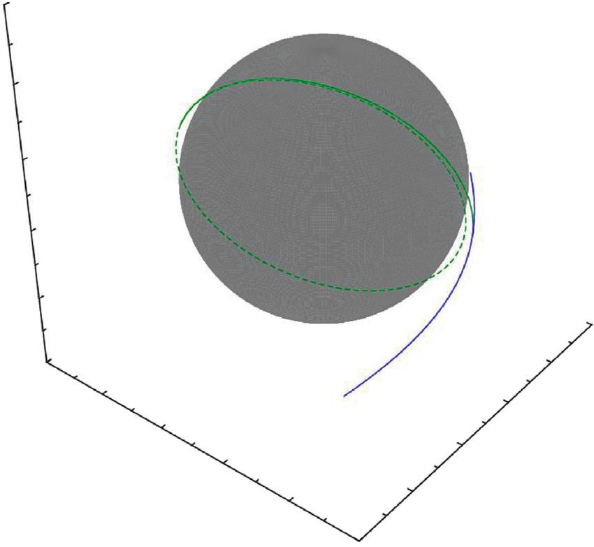
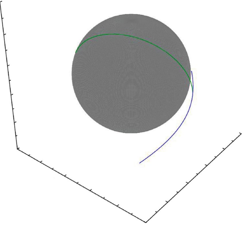
Mathematical Problems in Engineering 11

 Table 5: SmallSat mission characteristics for the year 2031 for the orbiter and impactor mission case.
 Delta-V for an orbiter Delta-V for an impactor
Periapsis altitude at Periapsis velocity at mission (km/s) mission (km/s)
deployment (km) deployment (km/s)
 ΔVrel ΔVsec ΔVMOI ΔVMOI
198.084 2.444 0.874 0.021 0.895 0.896

 Trajectory in Earth-centered frame Earth-Mars trajectory plots
 1E6 3E8

 8E5
 2E8
 5E5
 Lunar flyby
 (Jan. 11, 2031) 1E8
 2E5 Earth SOI
 Y-axis (km)

 Y-axis (km)
 crossing
 (Jan. 17, 2031)
 0 0
 Departure
 Earth SOI (Jan. 8, 2031)
 –2E5
 crossing –1E8
 (Jan. 17, 2031)
 –5E5 Mars arrival
 (Nov. 9, 2031)
 –2E8
 –8E5

 –1E6 –3E8
 –1E6 –8E5 –5E5 –2E5 0 2E5 5E5 8E5 1E6 –3E8 –2E8 –1E8 0 1E8 2E8 3E8
 X-axis (km) X-axis (km)
 Lunar orbit Earth SOI Earth orbit
 Lunar SOI Trajectory Mars orbit
 Trajectory
 (a) (b)

Figure 3: Example transfer trajectory of a 2031 mission. The left side shows the transfer trajectory inside of Earth’s SOI, and the right side
shows the Sun-centered Earth-Mars transfer trajectory.

characteristics for this year, including the periapsis altitude mothership departs the Earth on Jan. 8, 2031, performs a
and velocity of the SmallSat at the moment of release, are flyby of the Moon on Jan. 11, 2031, and escapes the Earth’s
shown. In the previous section, we showed that a total SmallSat SOI on Jan. 17, 2031. The total flight time of the mothership
mass of approximately 200 kg can be deployed around the escaping the Earth’s SOI is approximately 9.88 days. After
Moon with an Ariane 5 launch vehicle using the EMMGA the mothership escapes the Earth’s SOI, it continues its
transfer option, which is comparable to that of the EMD journey to Mars (right side of Figure 3) and arrives on Nov.
transfer option. Assuming 277 s of Isp_s [41], which is one of 9, 2031, which is approximately 296 days from its departure
the highest Isp values for currently available miniaturized from Earth. The total TOF for the mothership is approxi-
thrusters, approximately 143.8 kg of dry mass is allowed when mately 305 days, and the required ΔVTotal is approximately
performing a mission around the Moon (143.876 kg for an 8.006 km/s. In Table 6, detailed trajectory information for
orbiter and 143.823 kg for an impactor). Although the current the 2031 mission is summarized. As shown in Table 6, the
analysis is performed using several assumptions that simplified values of ttof_E–M and ΔVAdd. are located at the lower limits
the current problem, sending an approximately 200-kg-class of the search range under the current simulation conditions.
SmallSat with a dry mass of approximately 140 kg with a single Due to the simulation conditions discussed previously, the
launch would certainly fulfill the requirements of the results of the 2031 case may not significantly differ for lower
worldwide scientific community. search range limits. However, the limits of these values can
 be further tuned for more detailed analysis by adapting an
 optimization scheme. During the mothership’s lunar flyby,
4.3. Example of a Transfer Trajectory. This subsection the SmallSat is released to perform its own mission. The
presents an example transfer trajectory of a 2031 mission SmallSat is deployed at an altitude of approximately
that utilizes the EMMGA transfer option. Figure 3 depicts 198.1 km at the periapsis passage of the mothership. The
the entire transfer trajectory from Earth departure to Mars corresponding time is Jan. 11, 2031, 20 : 57 : 26.770 (TDB),
arrival. The left side of Figure 3 represents the trajectory of and the SmallSat’s mission around the Moon is then per-
the 1st stage of the proposed conceptual mission in which the formed. Figure 4 shows an example of the SmallSat’s mission
12 Mathematical Problems in Engineering

Table 6: Detailed trajectory data of the mothership for the 2031 orbit around the Moon after 61.2 min of transfer, and for the
mission. impactor case, approximately 58.8 min will be required to
tTLI date Jan. 8, 2031 impact the lunar surface.
tArr date Nov. 9, 2031
ttof_E− M (days) 4.000 5. Conclusions
ΔVadd (m/s) − 2.000
TLI maneuver direction Ascending The current work proposes the concept of a multipurpose
tp (TDB) Jan. 11, 2031, 20 : 57 : 26.770 mission that can explore both the Moon and Mars with a
hp (km) 198.084 single launch and analyzes potential launch opportunities
ttof_SOI (days) 9.885
 for early-phase design work. For the mothership to reach
tSOI (TDB) Jan. 17, 2031, 21 : 15 : 48.672
vSOI (km/s) 1.187 Mars, the EMMGA trajectory is adapted for the trajectory
ΔVDep (km/s) 3.112 design basis, and the daughtership is assumed to be released
ΔVSOI (km/s) 2.004 from the mothership during the lunar flyby to perform its
ΔVArr (km/s) 2.890 own mission. To investigate potential launch opportunities,
ΔVTotal (km/s) 8.006 the associated delta-Vs have been derived and compared
Total time of flight (days) 305.000 with the solutions provided by typical EMD transfer options
 with a simplified dynamic model to focus on the preliminary
 Orbiter design studies. Additionally, two different lunar capture
 2.5E3 The Moon
 trajectory scenarios (orbiting and impacting cases) have been con-
 sidered to investigate the SmallSat mission capabilities. The
 1.5E3 launch opportunities for the years 2026 through 2045 have
 Second been investigated. The analysis confirms that, regardless of
 5.0E2 burn
 transfer type and mission period, the EMMGA transfer
 Z (km)

 point
 First burn options generally require a greater delta-V than the EMD
 –5.0E2
 point options. However, two candidate launch years have been
 –1.5E3
 (perilune) identified; the year 2031, and possibly 2045, may be the
 2.5E3 strongest candidate for a mission with the EMMGA option.
 –2.5E3 1.5E3 In both years, the proposed conceptual mission is expected
 –1.5E3 Mother- 5.0E2 to be performed with only slightly greater delta-Vs, ap-
 ship proximately 0.5 km/s and 0.6 km/s, respectively, than those
 )

 –5.0E2
 m

 –5.0E2
 (k

 X( 5.0E2 trajectory of the Type II-A EMD transfer option of the 2031 and 2045
 Y

 km –1.5E3
 ) 1.5E3 missions, respectively. To further improve the delta-V ef-
 2.5E3 ficiency by adapting the strategies discussed, the overall
 (a) mission delta-V difference between the EMD and EMMGA
 options are expected to be minimized compared to the
 2.5E3 The Moon Impactor
 current estimated values. The differences in delta-Vs are
 trajectory
 mainly caused by differences in the launch and arrival ge-
 1.5E3 ometries, especially the geometry at the Mars arrival date, for
 the EMMGA and EMD transfer options. Three different
 5.0E2 currently available heavy launch vehicles (Ariane 5, Proton
 Z (km)

 Impact M, and Atlas V) were selected as candidate launchers, and
 –5.0E2 point Release point the associated mass budgets were roughly analyzed. In-
 (perilune)
 terestingly, up to approximately 15% more dry mass can be
 –1.5E3
 2.5E3 delivered to Mars by using the EMMGA transfer option
 –2.5E3 1.5E3 instead of the Type II-A EMD transfer option with the
 –1.5E3 Mother- 5.0E2 Ariane 5 launcher in the year 2031. For the 2045 mission,
 ) approximately 9% more dry mass can be delivered when the
 –5.0E2 ship –5.0E2 m
 (k
 X( 5.0E2 trajectory Y EMMGA and Type II-A of EMD options are compared for
 km –1.5E3
 ) 1.5E3 the Ariane 5 launcher. Although the estimation of the
 2.5E3 current launcher’s payload delivery capabilities did not
 consider detailed launch constraints, rough dry mass ratio
 (b)
 estimates of 15% and 9% correspond to approximately
Figure 4: Example trajectory for a SmallSat mission around the 200 kg and 145 kg, respectively, which appear to be sufficient
Moon in 2031. The figure in the top shows the orbiter case, and the for a SmallSat class mission around the Moon. Indeed, as the
figure in the bottom is the impactor case. current work was performed under several assumptions to
 simplify the problem and focus on the preliminary analysis,
trajectory around the Moon for the orbiter (top) and im- many challenges still require resolution for this conceptual
pactor cases (bottom). For the orbiter mission case, the mission to be realized, and substantial research may be
SmallSat is inserted into a final 100-km-altitude circular required. However, the narrowed candidate launch window
You can also read