Residual Stresses in Selective Laser Melted Samples of a Nickel Based Superalloy - OPUS 4
←
→
Page content transcription
If your browser does not render page correctly, please read the page content below
Residual Stresses 2018 – ECRS-10                                                                  Materials Research Forum LLC
Materials Research Proceedings 6 (2018) 259-264                              doi: http://dx.doi.org/10.21741/9781945291890-41

        Residual Stresses in Selective Laser Melted Samples of a
                        Nickel Based Superalloy
    Arne Kromm1,a,*, Sandra Cabeza2,b, Tatiana Mishurova1,c, Naresh Nadammal1,d
                       Tobias Thiede1,e and Giovanni Bruno1,f
    1
       Bundesanstalt für Materialforschung und -prüfung (BAM), Unter den Eichen 87, 12205 Berlin,
                                               Germany
   2
     Institut Max von Laue - Paul Langevin (ILL), 71 Avenue des Martyrs, 38000 Grenoble, France
                      a
                    arne.kromm@bam.de, bcabeza@ill.fr, ctatiana.mishurova@bam.de,
              d
               naresh.nadammal@bam.de, etobias.thiede@bam.de, fgiovanni.bruno@bam.de

  Keywords: Additive Manufacturing, Selective Laser Melting, Residual Stresses

  Abstract. Additive Manufacturing (AM) through the Selective Laser Melting (SLM) route offers
  ample scope for producing geometrically complex parts compared to the conventional
  subtractive manufacturing strategies. Nevertheless, the residual stresses which develop during
  the fabrication can limit application of the SLM components by reducing the load bearing
  capacity and by inducing unwanted distortion, depending on the boundary conditions specified
  during manufacturing. The present study aims at characterizing the residual stress states in the
  SLM parts using different diffraction methods. The material used is the nickel based superalloy
  Inconel 718. Microstructure as well as the surface and bulk residual stresses were characterized.
  For the residual stress analysis, X-ray, synchrotron and neutron diffraction methods were used.
  The measurements were performed at BAM, at the EDDI beamline of -BESSY II synchrotron-
  and the E3 line -BER II neutron reactor- of the Helmholtz-Zentrum für Materialien und Energie
  (HZB) Berlin. The results reveal significant differences in the residual stress states for the
  different characterization techniques employed, which indicates the dependence of the residual
  state on the penetration depth in the sample. For the surface residual stresses, longitudinal and
  transverse stress components from X-ray and synchrotron agree well and the obtained values
  were around the yield strength of the material. Furthermore, synchrotron mapping disclosed
  gradients along the width and length of the sample for the longitudinal and transverse stress
  components. On the other hand, lower residual stresses were found in the bulk of the material
  measured using neutron diffraction. The longitudinal component was tensile and decreased
  towards the boundary of the sample. In contrast, the normal component was nearly constant and
  compressive in nature. The transversal component was almost negligible. The results indicate
  that a stress re-distribution takes place during the deposition of the consecutive layers. Further
  investigations are planned to study the phenomenon in detail.
  Introduction
  Additive manufacturing (AM) offers the opportunity to produce geometrically complex parts
  compared to the traditional production technologies. An important AM technology for metals is
  selective laser melting (SLM), where a part is produced by melting a powder bed in layers [1].
  However, residual stresses that arise during the process may limit the application of SLM parts
  by inducing unwanted distortion depending on the boundary conditions. Strategies for stress
  optimization must be developed to minimise distortion and with focus on other sensitive
  properties relying on residual stress. The material used in this study is the nickel based super
  Alloy 718 which has several applications in aerospace and chemical industry due its superior

         Content from this work may be used under the terms of the Creative Commons Attribution 3.0 license. Any further distribution of
this work must maintain attribution to the author(s) and the title of the work, journal citation and DOI. Published under license by Materials
Research Forum LLC.

                                                                    259
Residual Stresses 2018 – ECRS-10                                             Materials Research Forum LLC
Materials Research Proceedings 6 (2018) 259-264         doi: http://dx.doi.org/10.21741/9781945291890-41

 corrosion and heat resistance [2]. The SLM process is generally known to form a high amount of
 residual stresses due to the high temperature gradient present during laser melting. In principle
 the mechanisms of stress formation are similar to the fusion welding process. In the absence of
 solid state phase transformations tensile residual stresses are formed due to the hindered
 shrinkage of the already solidified material. The amount of stresses can be equal to the yield
 stress. After cooling to ambient temperature, a residual stress gradient between surface and core
 regions of the part is present. Its magnitude depends amongst others on the geometry and the
 stiffness of the whole part as well [3-8]. Adopting the scanning strategy during SLM can alter the
 level and distribution of the residual stresses [9-12]. Typically, the scanning is performed cyclic
 in sectors along the parts. This alters the heat flow and therefore the local temperature
 distribution. As a consequence, the stress formation is locally affected. However, the thermal-
 mechanical behaviour is complex and therefore to be evaluated by experimental investigation as
 a basis for modelling [5, 12-14]. This enables deliberate adjustment of process parameters to
 control the residual stresses and associated distortion during fabrication. In order to evaluate
 localised residual stress distributions in SLM parts different regions have to be investigated.
 Beside the surface and the bulk, the sub-surface area is of particular interest. Diffraction methods
 enable for non-destructive measurement of spatial resolved stress distributions. X-ray and
 neutron diffraction are appropriate to cover surface and bulk. On the other hand, the intermediate
 area (sub-surface) is accessible by the application of high energy synchrotron diffraction [15].
 This study aims at the characterization of residual stresses in SLM parts by using different
 diffraction measurement techniques.
 Experimental
 Alloy 718 was processed and provided by SIEMENS AG, Power and Gas, Berlin, Germany. The
 specimens were produced on an EOS M290 machine using the standard EOS parameter set for
 Alloy 718. The processing parameters, like track width, scan speed and power input, are
 confidential but were kept constant during fabrication. The deposition of each layer during the
 SLM process was identical with the hatching and scanning along the length and the width of the
 specimens, respectively. The residual stresses were determined using three complimentary
 techniques. The surface and the sub-surface was characterised by laboratory X-ray as well as
 high energy synchrotron diffraction (instrument EDDI at Bessy HZB, Berlin) using the sin²ψ-
 method [16]. Due to high energy, up to 150 keV, penetration depths of up to 100 µm are
 achievable at EDDI depending on the lattice plane evaluated [17]. The sample bulk was
 measured by neutron diffraction (instrument E3 at HZB Berlin) [18]. Table 1 gives important
 parameters for each measurement setup. The {311} diffraction line of nickel was used for stress
 evaluation in case of X-ray diffraction and for neutron diffraction. Synchrotron measurements
 were conducted in energy dispersive (EDXRD) mode using a white beam [17]. Therefore, up to
 four diffraction lines (see Table 1) could be utilised. Their mean value (weighted by their
 multiplicity) was taken for the stress evaluation.
    The SLM specimens were cuboids with a length of 100 mm and a width of 20 mm. The
 longitudinal edges were shaped round. Each measurement was conducted in a quarter of the
 sample along two lines as indicated in Fig. 1. Symmetry of the residuals stresses with respect to
 the centre of the sample was assumed. One measuring line was placed along the centre of the
 sample, while the other one was in parallel along the edge. For X-ray and synchrotron diffraction
 the measurement was conducted in the surface according to the penetration depth of the radiation
 up to 60 µm. In case of neutron diffraction, the measuring lines were placed at a distance of
 2 mm below the sample top surface. The microstructural characterisation included optical
 microscopy and Electron Back-Scattered Diffraction (EBSD). For this purpose, a small volume
 representing the transverse cross section of the sample was prepared by electrical discharge
 machining (EDM), see Fig. 1. Additionally, powder taken from this area served as stress free
 reference for neutron diffraction.

                                                  260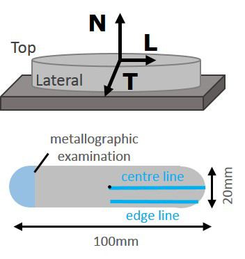
Residual Stresses 2018 – ECRS-10                                             Materials Research Forum LLC
Materials Research Proceedings 6 (2018) 259-264         doi: http://dx.doi.org/10.21741/9781945291890-41

             Table 1. Measuring and evaluation parameters for residual stress analyses
                    X-ray diffraction Synchrotron diffraction                    Neutron diffraction
 Radiation          Mn Kα             White beam E = 50 keV-150 keV              λ = 1.476 Å
 Diffraction line   Ni{311}           Ni{111}, Ni{200}, Ni{220},                 Ni{311}
                                      Ni{311}
 2Θ angle           156°              10°                                        85.3°
 Gauge volume       ø 2 mm collimator 1×1 mm² (primary beam)                     4 × 4 × 2 mm³
 Stress             long, trans       long, trans                                long, trans, norm
 components
 Exposure time      5s                    300 s                                    900 s
 DEC                s1(hkl) and ½s2(hkl) calculated from the single crystal constants using the
                    Eshelby/Kröner-model

  Figure. 1. Schematic of the sample with measuring lines located in the centre and along the edge
                  as well as the area considered for metallographic examination
 Results
 Microstructure. The parts produced by SLM process showed typical features characteristic to
 multi-pass welds but on a micro scale. As can be seen from Fig. 2 the bulk of the sample
 consisted of small overlapping runs. The heat flow was opposite to the building direction which
 leads to a columnar growth of the grains. Strong rotated cube texture specific of the heat
 dissipation along the specimen thickness was observed along the building direction, which is
 partly attributed to the shorter hatch length utilized for the SLM.

     Figure 2. Cross section of the bulk by light optical microscopy (left), {100} and {111} pole
                  figures obtained by EBSD showing rotated cube texture (right)

                                                  261
Residual Stresses 2018 – ECRS-10 Materials Research Forum LLC
Materials Research Proceedings 6 (2018) 259-264 doi: http://dx.doi.org/10.21741/9781945291890-41
Residual stresses. The residual stresses obtained by X-ray diffraction are shown in Fig. 3 (left).
In longitudinal as well as transverse direction the stresses were in tension. No gradient was
present along the sample centreline. While the stresses in longitudinal direction showed values
between 600 MPa and 850 MPa the stresses in transverse direction were significantly higher.
Values around 1000 MPa indicate stresses comparable to the yield point of the wrought alloy. No
differences were observed for the sample centre and the edge line. The stress distribution is
uniform along the top surface.
Figure 3. Longitudinal and transverse residual stresses in the top-surface obtained by X-ray
diffraction at the sample centre and edge line (left) and in the sub-surface obtained by
synchrotron diffraction at the sample centre and edge line (right)
With increasing penetration depth, the residual stresses changed their magnitude and also
distribution as shown in Fig. 3 (right). In longitudinal direction the residual stress level was
slightly shifted in parallel to values between 400 MPa and 800 MPa. Only a slight gradient was
present along the measuring line indicating lower stresses in the sample centre. This gradient was
more pronounced in transverse direction were the stresses in the centre were significantly
lowered even to compressive values of -100 MPa. Far from the centre of the sample the stresses
remained in tension showing approximately 400 MPa. As already indicated by X-ray diffraction
the measured centre line and edge line of the sample are comparable showing the same stress
gradients.
Different stress characteristics are to be found in the bulk of the sample 2 mm below the top
surface (see Fig. 4). Lower tensile longitudinal stresses were present along the sample length
which turned into compression (-250 MPa) in the border region. Transverse stresses were
balanced around zero at the measured centre line.
Figure 4. Longitudinal and transverse residual stresses (left) and normal residual stresses
(right) in the bulk obtained by neutron diffraction at the sample centre and edge line
262Residual Stresses 2018 – ECRS-10 Materials Research Forum LLC
Materials Research Proceedings 6 (2018) 259-264 doi: http://dx.doi.org/10.21741/9781945291890-41
Considering the measured edge line, the transverse stresses were shifted in parallel into
compression up to -300 MPa. On the other hand, longitudinal stresses remained in tension at a
similar level compared to the centre line.
The normal stress components in the sample bulk are shown in Fig. 4 (right). The distribution
and also the level of the stresses is similar in the centre and the edge line. The stresses are
constant around -200 MPa.
Taking into account all the stresses determined by the different measuring techniques applied
it becomes clear that a significant stress redistribution took place during deposition of the single
layers during the SLM process. The highest tensile stresses were always formed in the very last
deposited layer. Immediately after reheating by deposition of the following layers the stresses
were lowered especially transversely in the sample centre region. With ongoing deposition of
layers and increasing distance to the top surface the stresses were then shifted to lower tensile or
even compressive values due to the balance of forces.
Summary
Three different diffraction measuring techniques featuring different penetration depths were
capable to determine localised residual stress profiles in samples of nickel-based superalloy 718
manufactured by SLM. Using X-ray diffraction, longitudinal and transverse stress components in
the top surface showed high tensile values up to the yield limit. In the intermediate zone below
the surface, synchrotron diffraction disclosed a pronounced stress gradient along the length of the
sample for both stress components. Particularly, the transverse residual stress relaxed very
quickly towards the centre of the sample. Residual stresses analysed by neutron diffraction in the
bulk showed considerably lowered stresses proving the stress re-distribution during deposition of
the SLM layers. Even compressive stresses were found in transverse and predominantly normal
direction in the sample.
References
[1] L.E. Murr, S.M. Gaytan, D.A. Ramirez, E. Martinez, J. Hernandez, K.N. Amato, P.W.
Shindo, F.R. Medina, R.B. Wicker, Metal Fabrication by Additive Manufacturing Using Laser
and Electron Beam Melting Technologies, J Mater Sci Technol 28(1) (2012) 1-14.
https://doi.org/10.1016/S1005-0302(12)60016-4
[2] K.N. Amato, S.M. Gaytan, L.E. Murr, E. Martinez, P.W. Shindo, J. Hernandez, S. Collins, F.
Medina, Microstructures and mechanical behavior of Inconel 718 fabricated by selective laser
melting, Acta Mater 60(5) (2012) 2229-2239. https://doi.org/10.1016/j.actamat.2011.12.032
[3] P. Mercelis, J.P. Kruth, Residual stresses in selective laser sintering and selective laser
melting, Rapid Prototyping J 12(5) (2006) 254-265. https://doi.org/10.1108/13552540610707013
[4] C.E. Protasov, V.A. Safronov, D.V. Kotoban, A.V. Gusarov, Experimental study of residual
stresses in metal parts obtained by selective laser melting, Laser Assisted Net Shape Engineering
9 International Conference on Photonic Technologies Proceedings of the Lane 2016 83 (2016)
825-832.
[5] L. Van Belle, G. Vansteenkiste, J.C. Boyer, Investigation of residual stresses induced during
the selective laser melting process, Key Eng Mater 554-557 (2013) 1828-1834.
https://doi.org/10.4028/www.scientific.net/KEM.554-557.1828
[6] M.S. Abdul Aziz, T. Furumoto, K. Kuriyama, S. Takago, S. Abe, A. Hosokawa, T. Ueda,
Residual Stress and Deformation of Consolidated Structure Obtained by Layered Manufacturing
Process, J Adv Mech Des Syst 7(2) (2013) 244-256. https://doi.org/10.1299/jamdsm.7.244
263Residual Stresses 2018 – ECRS-10 Materials Research Forum LLC
Materials Research Proceedings 6 (2018) 259-264 doi: http://dx.doi.org/10.21741/9781945291890-41
[7] T. Mishurova, S. Cabeza, T. Thiede, N. Nadammal, A. Kromm, M. Klaus, C. Genzel, C.
Haberland, G. Bruno, The Influence of the Support Structure on Residual Stress and Distortion
in SLM Inconel 718 Parts, Metallurgical and Materials Transactions A (2018).
[8] N. Nadammal, A. Kromm, R. Saliwan-Neumann, L. Farahbod, C. Haberland, P. Portella,
Influence of Support Configurations on the Characteristics of Selective Laser-Melted Inconel
718, Jom-Us 70(3) (2018) 343-348. https://doi.org/10.1007/s11837-017-2703-1
[9] B. Chong, S. Shrestha, Y.K. Chou, Stress and Deformation Evaluations of Scanning Strategy
Effect in Selective Laser Melting, Proceedings of the Asme 11th International Manufacturing
Science and Engineering Conference, 2016, Vol 3 (2016). https://doi.org/10.1115/MSEC2016-
8819
[10] Y. Liu, Y.Q. Yang, D. Wang, A study on the residual stress during selective laser melting
(SLM) of metallic powder, Int J Adv Manuf Tech 87(1-4) (2016) 647-656.
https://doi.org/10.1007/s00170-016-8466-y
[11] Y.J. Lu, S.Q. Wu, Y.L. Gan, T.T. Huang, C.G. Yang, J.J. Lin, J.X. Lin, Study on the
microstructure, mechanical property and residual stress of SLM Inconel-718 alloy manufactured
by differing island scanning strategy, Opt Laser Technol 75 (2015) 197-206.
https://doi.org/10.1016/j.optlastec.2015.07.009
[12] N. Nadammal, S. Cabeza, T. Mishurova, T. Thiede, A. Kromm, C. Seyfert, L. Farahbod, C.
Haberland, J.A. Schneider, P.D. Portella, G. Bruno, Effect of hatch length on the development of
microstructure, texture and residual stresses in selective laser melted superalloy Inconel 718,
Mater Design 134 (2017) 139-150. https://doi.org/10.1016/j.matdes.2017.08.049
[13] M. Shiomi, K. Osakada, K. Nakamura, T. Yamashita, F. Abe, Residual stress within
metallic model made by selective laser melting process, Cirp Ann-Manuf Techn 53(1) (2004)
195-198. https://doi.org/10.1016/S0007-8506(07)60677-5
[14] J.P. Kruth, J. Deckers, E. Yasa, R. Wauthle, Assessing and comparing influencing factors of
residual stresses in selective laser melting using a novel analysis method, P I Mech Eng B-J Eng
226(B6) (2012) 980-991.
[15] C. Genzel, C. Stock, W. Reimers, Application of energy-dispersive diffraction to the
analysis of multiaxial residual stress fields in the intermediate zone between surface and volume,
Mat Sci Eng a-Struct 372(1-2) (2004) 28-43. https://doi.org/10.1016/j.msea.2003.09.073
[16] E. Macherauch, P. Müller, Das sin²ψ - Verfahren der röntgenografischen
Spannungsmessung, Zeitschrift für angewandte Physik 13 (1961) 305-312.
[17] C. Genzel, I.A. Denks, J. Gibmeler, M. Klaus, G. Wagener, The materials science
synchrotron beamline EDDI for energy-dispersive diffraction analysis, Nucl Instrum Meth A
578(1) (2007) 23-33. https://doi.org/10.1016/j.nima.2007.05.209
[18] T. Poeste, R.C. Wimpory, R. Schneider, The new and upgraded neutron instruments for
material science at HMI - current activities in cooperation with industry, Residual Stresses Vii
524-525 (2006) 223-228. https://doi.org/10.4028/0-87849-414-6.223
264You can also read