Review: Filament Winding and Automated Fiber Placement with In Situ Consolidation for Fiber Reinforced Thermoplastic Polymer Composites
←
→
Page content transcription
If your browser does not render page correctly, please read the page content below
polymers
Review
Review: Filament Winding and Automated Fiber Placement
with In Situ Consolidation for Fiber Reinforced Thermoplastic
Polymer Composites
Yi Di Boon * , Sunil Chandrakant Joshi                      and Somen Kumar Bhudolia *

                                          School of Mechanical and Aerospace Engineering, Nanyang Technological University, 50 Nanyang Avenue,
                                          Singapore 639798, Singapore; mscjoshi@ntu.edu.sg
                                          * Correspondence: ydboon@ntu.edu.sg (Y.D.B.); somenkum001@e.ntu.edu.sg (S.K.B.)

                                          Abstract: Fiber reinforced thermoplastic composites are gaining popularity in many industries
                                          due to their short consolidation cycles, among other advantages over thermoset-based composites.
                                          Computer aided manufacturing processes, such as filament winding and automated fiber placement,
                                          have been used conventionally for thermoset-based composites. The automated processes can be
                                          adapted to include in situ consolidation for the fabrication of thermoplastic-based composites. In this
                                          paper, a detailed literature review on the factors affecting the in situ consolidation process is presented.
                                          The models used to study the various aspects of the in situ consolidation process are discussed.
                                          The processing parameters that gave good consolidation results in past studies are compiled and
                                          highlighted. The parameters can be used as reference points for future studies to further improve the
                                          automated manufacturing processes.


                                          Keywords: thermoplastic resin; process modeling; filament winding; automated fiber placement
Citation: Boon, Y.D.; Joshi, S.C.;
Bhudolia, S.K. Review: Filament
Winding and Automated Fiber
Placement with In Situ Consolidation
for Fiber Reinforced Thermoplastic        1. Introduction
Polymer Composites. Polymers 2021,              Fiber reinforced polymer (FRP) composites have very high specific strength and stiffness.
13, 1951. https://doi.org/10.3390/        These favorable properties led to FRP composites becoming more popular in many industries,
polym13121951                             such as aerospace, automotive, sports, construction, offshore, and so on [1–7]. Advancements
                                          in computer aided manufacturing processes for FRP composites, such as automated fiber place-
Academic Editor: Victor Tcherdyntsev
                                          ment (AFP) and filament winding (FW), have greatly improved the production throughput
                                          and the quality of FRP composite components. Epoxy, a thermoset polymer, is commonly used
Received: 19 May 2021
                                          as the matrix material in FRP composites because of its excellent mechanical strength. However,
Accepted: 9 June 2021
                                          one of the major drawbacks of thermoset based FRP composites is their long curing cycle,
Published: 11 June 2021
                                          which results in increased manufacturing costs. In contrast, the manufacturing of fiber rein-
                                          forced thermoplastic polymer (FRTP) composites is generally much less time consuming due to
Publisher’s Note: MDPI stays neutral
                                          their short consolidation cycles. Besides this, FRTP composites also have other advantages over
with regard to jurisdictional claims in
                                          thermoset based FRP composites, including higher toughness, long shelf life, ease of repairing
published maps and institutional affil-
iations.
                                          and potential for recycling [4]. High performance thermoplastic polymers, such as polyether
                                          ether ketone (PEEK), can also maintain their mechanical properties in environments with
                                          elevated temperature and moisture [8,9]. For FRTP composite components, their fabrication
                                          using AFP and FW processes can include in situ consolidation (ISC) to further shorten the
                                          processing time required.
Copyright: © 2021 by the authors.
                                                Many studies have been carried out on the manufacturing of FRTP composites using
Licensee MDPI, Basel, Switzerland.
                                          AFP and FW with ISC. Researchers used various material forms and ISC methods in their
This article is an open access article
                                          studies, leading to different heat transfer and consolidation mechanisms. In this review,
distributed under the terms and
                                          a comprehensive overview on the topic, encompassing the different material forms and
conditions of the Creative Commons
Attribution (CC BY) license (https://
                                          ISC methods, is presented. Experimental and numerical studies on the factors affecting
creativecommons.org/licenses/by/
                                          the ISC process are discussed, with attention given to recent studies. The optimization of
4.0/).                                    the AFP and FW processes with ISC is deliberated, with emphasis given to the physical

Polymers 2021, 13, 1951. https://doi.org/10.3390/polym13121951                                            https://www.mdpi.com/journal/polymers
Polymers 2021, 13, 1951                                                                                           2 of 29

                          and mechanical properties of the FRTP component fabricated, as well as the productivity
                          of the process. A summary of the optimized processing parameters from past studies is
                          also presented, providing a basis for future studies on further improving the fabrication of
                          FRTP components using AFP and FW with ISC.

                          2. Manufacturing of FRTP Composites
                                The manufacturing of FRTP components generally involves three stages, namely
                          heating, consolidation and cooling. In the heating stage, the thermoplastic matrix is melted
                          or softened so that bonding can occur. Pressure is applied in the consolidation stage to
                          produce components with low void content. During the cooling stage, the cooling rate is
                          controlled to obtain the desired microstructure in the thermoplastic [4].
                                The autoclave process and compression molding are two commonly used manufac-
                          turing processes for FRTP composites in the industry. For the autoclave process, the FRTP
                          preform is laid on a tool, by hand or using AFP, and sealed in a vacuum bag assembly.
                          The vacuum bag assembly can include release films, a bleeder, a breather, a vacuum bag
                          and sealants. The assembly is then put into an autoclave where heat and pressure are
                          applied to the FRTP composite [4,10]. Advantages of the autoclave process include being
                          able to fabricate large and complex components, as well as the consistency in the quality of
                          components produced [10]. However, the process is difficult to automate. Consolidation
                          also takes longer due to the convection heating involved [4]. For FRTP composites with
                          high performance thermoplastic matrix, high-temperature vacuum bagging materials,
                          which are difficult to handle, need to be used [10].
                                In compression molding, the FRTP component is formed from a preform using a
                          compression press and a mold set. Similar to the autoclave process, the preform can be
                          made by hand layup or using AFP. Prior to molding, the preform can be preheated in
                          an oven. The preform is then compressed between the upper and lower molds (or ‘core
                          and cavity’) using a compression press to give the component its shape. Heat is also
                          applied during this stage [4,11]. Advantages of compression molding include its short
                          processing cycles and being suitable for automation [4,11]. However, FRTP components
                          fabricated using automated compression molding tend to have defects caused by wrinkles
                          and waviness in the fiber reinforcement [11].
                                Computer aided manufacturing processes such as AFP and FW have several advan-
                          tages over the autoclave process and compression molding. One of the advantages is the
                          better precision in the fiber orientation that can be achieved. AFP and FW can also include
                          ISC to enable the fabrication of FRTP composite components in a single step, thus poten-
                          tially reducing production times. The AFP and FW processes with ISC are discussed in
                          more detail in the next sections.

                          2.1. Automated Fiber Placement
                               A schematic diagram of the AFP process for FRTP composites is shown in Figure 1.
                          Strips of FRTP prepreg tapes are laid on a tool usually by a robot arm equipped with a
                          fiber placement head. The feeding unit on the fiber placement head guides the prepreg
                          tapes onto the tool. The tape is heated at the nip point by a heat source and pressed onto
                          the substrate by a compaction roller for ISC. The tape is cut into strips of specified lengths
                          by the cutting unit. The AFP process is controlled by a computer program to lay the FRTP
                          prepreg tapes in the designed layup configuration.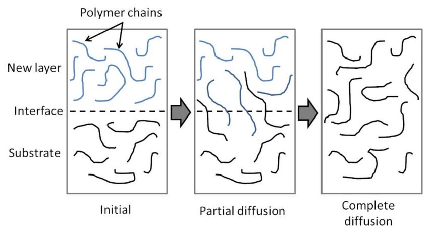
Polymers 2021, 13, 1951                                                                                            3 of 29

                          Figure 1. Automated fiber placement with in situ consolidation.

                                Advancements in AFP technology enabled the fabrication of FRTP composite com-
                          ponents with improved fiber direction accuracy compared to conventional fabrication
                          methods, such as hand layup, while reducing material wastage [12]. Advanced AFP
                          machines allow for fiber placement speeds (or line speeds) of up to 3 m/s [13]. For the fab-
                          rication of large components, multiple tapes can be placed simultaneously to increase the
                          productivity of the process [12]. For the fabrication of more complexed parts, the process is
                          constrained by factors such as the size of the compaction roller, the arrangements of the
                          feeding and cutting units, and the size of the heat source [13,14]. Some of the constraints
                          can be overcome by designing the fiber placement head with features such as multiple
                          compaction rollers with adjustable heights [13].
                                One of the major limiting factors to increasing the productivity of AFP processes is the
                          incidence of manufacturing defects requiring inspections and corrections [13]. One strategy
                          to alleviate the problem is to improve the defect detection using tools such as laser position-
                          ing systems [15] or online process monitoring methods such as thermographic imaging [13].
                          Sacco et al. presented a method using machine learning techniques in image processing
                          to detect and classify defects in AFP processes [16]. Another strategy is to gain a better
                          understanding of the effects of the defects on the performance of the FRP composite com-
                          ponent and develop defect tolerant designs. Croft et al. conducted experiments to study
                          the impacts of four different defect configurations, namely gap, overlap, half gap/overlap
                          and twisted tow [17]. Nguyen et al. expanded on the study and investigated defects of
                          various sizes [18]. Zhang et al. studied the tape wrinkling when placing prepreg tapes in
                          curves and developed a set of placement criteria to avoid wrinkling [19]. Reviews on the
                          effects of manufacturing defects in AFP and the methods for defect detection have been
                          presented by Oromiehie et al. [20] and Sun et al. [21].

                          2.2. Filament Winding
                               Figure 2 shows a schematic of a FW setup with ISC. FRTP yarns or prepreg tapes are
                          directed by the carriage and wound onto a rotating mandrel. For the fabrication of cylinders
                          or pipes, a simple 2-axis FW machine (as shown in Figure 2) is sufficient. For the fabrication
                          of parts with more complex geometry, such as pressure vessels with hemispherical end
                          domes, a FW machine with more axes of motions, such as a robot arm with a FW head, is
                          required. Similar to AFP, ISC is carried out using a heat source and a compaction roller.
                          FW is a continuous process where cutting the FRTP yarns or prepreg tapes is not required
                          during winding. As such, the yarns or tapes are usually tensioned throughout the process
                          by tensioners.
Polymers 2021, 13, 1951                                                                                            4 of 29

                          Figure 2. Filament winding with in situ consolidation.

                                FW has been used for decades to make axisymmetric FRP components, such as pipes,
                          pressure vessels, pipe fittings and drive shafts [22,23]. Recently, advancements in robotics
                          have made it possible to make components with more complexed shapes. Sorrentino
                          et al. used FW to fabricate a helicopter “fork” (a structural component connecting the
                          helicopter blade to the rotor) which is not axisymmetric [24]. The authors highlighted
                          the considerations in designing the FW process, including the winding trajectory, the
                          winding tool, the mold and the winding pattern. Beck et al. used FW to fabricate a 3D fiber
                          skeleton which is then overmolded through injection molding to form the final part [25].
                          The continuous fibers in the 3D skeleton are oriented strategically to be aligned to the
                          load path.

                          3. Materials
                               The fiber reinforcement in FRP composites is the main load bearing component.
                          Fiber reinforcements that are commonly used include carbon, glass and aramid. Carbon
                          fibers have very high stiffness and tensile strength, making them suitable for applications
                          in the aerospace industry. The reinforcement fibers need to be surface treated with the
                          proper sizing to ensure good fiber-matrix bonding in the FRP composite [26,27].
                               There are two types of thermoplastic polymers, namely semi-crystalline and amor-
                          phous thermoplastics. Semi-crystalline thermoplastics experience thermal transitions from
                          a solid or glassy state to a rubbery state at the glass transition temperature, Tg , and subse-
                          quently to a liquid state at the melting temperature, Tm . On the other hand, amorphous
                          thermoplastics only exhibits a Tg . Thermoplastic polymers are generally categorized into
                          two groups based on their performances, namely low cost thermoplastics and high perfor-
                          mance thermoplastics. Low cost thermoplastics include polypropylene (PP), polyethylene
                          (PE) and polyamides, such as PA6, PA66, and PA12. High performance thermoplastics
                          include polyether ether ketone (PEEK), polyether ketone ketone (PEKK), polyphenylene
                          sulphide (PPS), polyetherimide (PEI) and high temperature polyimides (TPI) [4,8,28].
                          The mechanical properties of high performance thermoplastics are comparable or better
                          than conventionally used thermosets such as epoxy. High performance thermoplastics also
                          have high Tg and high chemical resistance, allowing them to maintain their mechanical
                          properties in harsh environments [8,9]. Gabrion et al. reported that a carbon/TPI composite
                          retained its strengths in tensile and fatigue tests at temperatures up to 200 ◦ C [28].
                               For the processing of FRTP composites using FW and AFP, semi-finished forms of the
                          material system are generally used. For AFP, prepreg tapes are commonly used. For FW, in
                          addition to prepreg tapes, commingled yarns and powder impregnated fibers can also be
                          used [29]. The various semi-finished forms of FRTP composites are shown in Figure 3.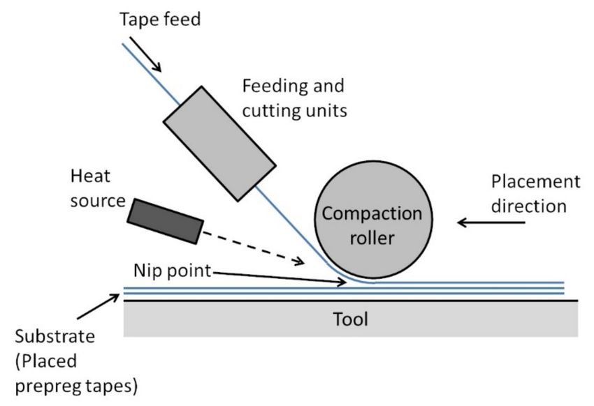
Polymers 2021, 13, 1951                                                                                         5 of 29

                          Figure 3. (a) Prepreg tape, (b) commingled yarn, (c) powder impregnated fibers.

                                Prepreg tapes are commonly produced through hot melt coating or pultrusion. High
                          pressure is applied during the coating to ensure good thermoplastic impregnation. The re-
                          sulting tapes are fully consolidated with very low void content [8]. Prepreg tapes with
                          uniform tape width and smooth tape surfaces are suitable for use in FW and AFP. For FW
                          and AFP using prepreg tapes, ISC only involves the bonding between the tapes and not
                          impregnation, thus allowing for higher line speeds [29]. The FRTP component fabricated
                          from prepreg tapes is also generally of better quality compared to using other semi-finished
                          forms [4,29]. One disadvantage of prepreg tapes is their low flexibility making it diffi-
                          cult to form complex parts with them [4,8]. Prepreg tapes are also more expensive than
                          commingled yarns and powder impregnated fibers [29,30]. Many FRTP materials, such
                          as carbon/PEEK, carbon/PA6 and carbon/PPS, are currently available in prepreg tape
                          form, and research on prepreg tapes for new material systems are ongoing. Iannone et al.
                          proposed a hybrid prepreg tape consisting of carbon/PEEK tapes with PEI films added on
                          the tape surfaces [31]. The hybrid prepreg tapes enable the fabrication of laminates with
                          PEEK matrix at the desired degree of crystallinity and amorphous PEI at the interlaminar
                          regions.
                                Commingled yarns are produced by intermingling reinforcement fibers with thermo-
                          plastic fibers. The reinforcement and thermoplastic fibers need to be distributed evenly in
                          the yarn to minimize the thermoplastic flow distance required to achieve good impregna-
                          tion during consolidation. The intermingling process is usually performed using air jets at
                          room or elevated temperatures [32]. More recently, the production of commingled yarns
                          using an online hybrid melt spinning technique is developed [26]. The technique enables
                          excellent intermingling of the fibers without damaging them, and sizing can be applied
                          in the same process. The use of commingled yarns allows for the fabrication of FRTP
                          components with uniform fiber volume content. Commingled yarns are also flexible and
                          can be woven into highly drapeable fabrics which can be used in stamp forming [32–34].
                          For FW using commingled yarns, researchers have studied the use of various heat sources
                          such as ultrasonic welding and hot gas torch for ISC [29,35,36].
                                Powder impregnated fibers are made of reinforcement fibers with fine dispersed
                          thermoplastic powder. In some products, an outer tube made of the same thermoplastic
                          material is added. However, the outer tube can lead to composite components with large
                          matrix rich region [9]. Powder impregnated fibers are produced by passing the reinforced
                          fibers through a fluidized bed (air fluidization) or an aqueous bath where thermoplastic
                          powders are dispersed onto the fibers [8,37,38]. The deposition of the powders is aided
                          by ionizing the powders or adding surfactants. This process enables thermoplastics with
                          very high melt viscosities to be used in FRTP composites [9]. Similar to commingled fibers,
                          powder impregnated fibers are flexible and can be woven into fabric forms [8,9].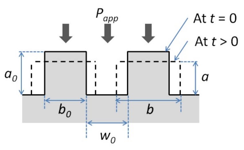
Polymers 2021, 13, 1951                                                                                             6 of 29

                               Henninger et al. proposed an FW process with online impregnation [39,40]. The re-
                          inforcement fibers and thermoplastic matrix are used in their raw forms. The online
                          impregnation is performed by passing the reinforcement fibers through porous impreg-
                          nation wheels. Molten thermoplastic polymer is squeezed from the inside of the wheels
                          through to the surface to impregnate the fibers. A hot air gun and a consolidation roller
                          are used for ISC. Henninger et al. reported that the FW process with online impregnation
                          led to lower costs overall due to the raw materials used [39]. By controlling the online
                          impregnation parameters, the process can be used to fabricate FRTP components with
                          varying fiber volume contents. However, the productivity is lower than FW processes using
                          semi-finished FRTP products because the line speed is limited by the fiber pretension [40].

                          4. Heat Sources for In Situ Consolidation
                               Temperature and dwell time (or exposure time) are two related parameters crucial
                          to the consolidation of FRTP composites. Low temperatures or short dwell times lead to
                          insufficient bonding, whereas temperatures which are too high or dwell times that are
                          overly long result in degradation and decomposition of the thermoplastic matrix [36,41,42].
                          The temperatures and dwell times achievable in the ISC process are limited by the heating
                          rate and the heating zone of the heat source. Therefore, the choice of the ISC heat source
                          affects the productivity of the AFP and FW processes, as well as the quality of the FRTP
                          composite component fabricated. Many different types of heat sources have been used for
                          ISC, including hot gas torch, infrared (IR) heater, laser and ultrasonic welder.
                               Hot gas torch has been widely used in AFP and FW due to its low capital cost [43,44].
                          It can also be attached to the AFP or FW heads easily [45]. Heat is transferred to the
                          thermoplastic through forced convection. Factors affecting the heat transfer include the
                          hot gas temperature, the gas flow rate and the distance of the nozzle to the nip point [45].
                          For consolidation requiring high temperatures, an inert gas, such as nitrogen, needs to be
                          used to prevent oxidation. This results in a significant increase in the operating costs [43,44].
                          Another drawback of the hot gas torch is its low energy efficiency [43,46]. In order to
                          improve the heating process, hot gas heating can be used together with methods such as
                          preheating of the composite fibers or tapes [36,47] and using a heated mandrel or tool [48].
                               An IR heater is another inexpensive option for heating FRTP composites. They are
                          also easy to operate. They have been used both for the preheating of incoming fibers or
                          tapes and as the main heat source for ISC. For the latter, IR spot heaters can output more
                          focused heating to achieve results that are better or comparable to a hot gas torch [44,49].
                          IR heaters transfer heat mainly through radiation. For the heating of powder impregnated
                          fibers with outer tubes using IR heaters, only the outer surface is exposed to IR radiation.
                          The heat needs to be transferred from the outer tube to the powders and the fibers through
                          conduction or convection, thus leading to a delay in the heating process [47]. Another
                          disadvantage of IR heaters is the inconsistent heating due to the residual heat in the heaters
                          after they are switched off [50]. The heat transfer from IR heaters is also less focused,
                          leading to inefficiencies [44].
                               Laser has been studied by many researchers for ISC. Lasers are characterized by their
                          very high radiation intensity which allows fast heating at a localized point [43,44]. Researchers
                          have used CO2 lasers for the consolidation FRTP composites such as carbon/PEEK and
                          glass/PPS in early studies [42,43]. However, using CO2 lasers can cause burning and oxidizing
                          at the surface of FRTP prepreg tapes as the radiation from CO2 lasers is absorbed by the
                          thermoplastic matrix [44]. More recently, high powered lasers such as near infrared (NIR)
                          diode lasers are used [51–53]. Diode lasers do not cause oxidation at the prepreg tape surface
                          as the radiation from diode lasers is absorbed by the carbon fibers instead of the thermoplastic
                          matrix [44]. The high power ratings of modern lasers (e.g., 3 kW [41]) compared to those
                          used in early studies (e.g., 80 W [42]) allow AFP or FW to be performed at very high line
                          speeds. Lasers are considerably more expensive than hot gas torch and IR heaters [43], thus
                          they are generally reserved for the processing of FRTP composites requiring high temperatures,
                          where other heating methods are considered insufficient. The implementation of a laser
Polymers 2021, 13, 1951 7 of 29
heating system is also more difficult. Additional processing parameters such as the laser
angle, the laser beam profile and the distance between the laser and the nip point need to be
taken into consideration [41,44,54]. Additionally, safety measures, such as having an enclosed
environment, need to be implemented.
Ultrasonic welding is a relatively new technique for ISC of FRTP composites. The tech-
nique has been proven to be effective in the joining and repairing of thermoplastic-based
components [55]. In ultrasonic welding, high frequency, low-amplitude ultrasonic vibra-
tion is applied to the thermoplastic surface through a sonotrode or horn to cause surface
and intermolecular friction, resulting in the heating and melting of the thermoplastic poly-
mer [35,56]. The advantages of ultrasonic welding include short processing time, good
localized heating and low energy requirement [55,56]. For ultrasonic ISC, the horn also acts
as a compaction unit to apply pressure onto the FRTP composite. Additional rollers can
be added to increase the contact time [35]. Researchers have studied the ultrasonic ISC of
FRTP composites in the forms of commingled yarns and prepreg tapes, with thermoplastic
matrices including poly(ethylene terephthalate) (PET), PP and high density polyethylene
(HDPE) [35,46,56,57]. One of the limitations of ultrasonic welding is the dependence of the
heat transfer process on the FRTP material properties, including stiffness, hardness and
damping response [55]. Rizzolo and Walczyk reported that ultrasonic welding is effective
for the consolidation of carbon/PET but less so for glass/HDPE [46].
Heraeus Noblelight developed a new flashlamp heating system named, humm3® ,
based on pulsed light technology [58]. The humm3® has very high heating rate and
excellent temperature control. The heating performance of the humm3® is comparable to
high powered lasers. However, unlike lasers, there is no restrictive safety requirements for
its application. Another advantage of the heating system is the small flashlamp head which
allows it to be used for the fabrication of complex parts using AFP. Nguyen et al. used
the flashlamp technology in the AFP of a hybrid material made for lightning protection,
consisting of a FRTP prepreg layer, a copper layer (expanded or perforated foil) and a
thermoplastic layer [59]. The line speed of 2400 mm/min was achieved for the process
temperature of 380 ◦ C.
5. Modeling Heat Transfer
The heat transfer process is a crucial part of the ISC of FRTP composites. Heat transfer
mechanisms are categorized into conduction, convection and radiation. For AFP and FW
with ISC, due to the various mechanisms involved and the complexity of the process, heat
transfer is often studied using numerical methods, such as finite element (FE) simulations
and finite difference methods (FDMs). In numerical simulations, the temperature field
for the material being studied is obtained by solving the heat equation, with the heat
transfer between the material and the environment modeled as boundary conditions.
From the energy balance principle, the general heat equation can be written as shown in
Equation (1) [60]:
∂T
ρC = −∇·q + φ (1)
∂t
where ρ is the material density, C is the specific heat capacity of the material, T is temper-
ature, t is time, q is the heat flux vector and φ is the volumetric rate of heat generation.
For semi-crystalline thermoplastic polymers, the latent heat of fusion and heat related to
crystallization can be modeled as a heat sink and a heat source respectively [61]. However,
they are small compared to other heat exchange mechanisms involved and thus are often
ignored [62,63]. The heat flux vector through the material, qmat , can be obtained using
Fourier’s law of heat conduction shown in Equation (2) [60]:
qmat = −k∇T (2)
where k is the thermal conductivity of the material and ∇T is the temperature gradient.
For FRTP composites, the thermal conductivity in the fiber direction is different from thePolymers 2021, 13, 1951 8 of 29
thermal conductivity in the transverse direction. Therefore, the heat flux in the fiber and
transverse directions need to be considered separately [62,64].
For the heat transfer boundary conditions, the heat flux vector, qbc , is often described
using a linear relation shown in Equation (3) [60]:
qbc ·n = h(T1 − T2 ) (3)
where n is the unit normal vector, h is the film heat transfer coefficient at the boundary,
T1 is the temperature of the material and T2 is the temperature of the heat source or the
environment. For heat transfer through conduction, radiation and convection, h is substi-
tuted by thermal conductivity at the boundary, kbc , the radiation heat transfer coefficient,
hr , and the convection heat transfer coefficient, hconv , respectively. For the radiation heat
exchange between the material and the environment, hr is approximated by representing
the material as a small body in a large enclosure. Using this representation, hr is defined as
shown in Equation (4) [65]:
3
hr = 4eσTref (4)
where e is the emissivity of the material, σ is the Stefan-Boltzmann constant and Tref = 12 (T1 + T2 ).
For convection, two types of convection are considered, namely forced and free convection. Forced
convection is the heat transfer between a surface and a flow of fluid that is driven by an external
agency, such as a pump, whereas free convection is the heat transfer caused by fluid flow due to
buoyancy [60,65]. For free convection in air, hconv is typically in the range of 1 to 50 W/(m2 ·K) [63,65].
For the modeling of ISC using forced convection heaters such as hot gas torch, many
researchers used constant heat coefficient values (hheater ) to model the heat transfer between
the heater and the FRTP material [66–68]. Tafreshi et al. discussed the determination of the
hheater value for ISC using hot gas torch using two approaches, namely (i) calculating hheater
from the Nusselt number and the Reynold number based on impinging jet theories, and
(ii) obtaining hheater by considering the energy absorbed by the material and then fitting
numerical calculations to experimental data [45]. The authors compiled the hheater values
for different nozzle temperatures, hot gas flow rates, and nozzle-substrate distances for
AFP with and without a roller. The data is useful for determining hheater for future studies
on the topic. In a recent study, Zacherl et al. noted that assuming a constant hheater for the
heating process using hot gas torch can lead to satisfactory predictions for the maximum
temperature, but the predicted heating and cooling rates differ from experiments [69].
A similar observation was reported by Tafreshi et al. [68]. In particular, the cooling rate
is important in determining the degree of crystallization of the thermoplastic in the ISC
process. Therefore, Zacherl et al. introduced two distribution functions to model the hheater
distributions along the length and width of the FRTP tape near the nip point [69]. Using the
hheater distributions, the authors showed that the heating and cooling rates predicted agreed
well with experiment. However, four additional parameters need to be determined through
experimental data fitting, making the use of the distribution functions more complex.
For the modeling of ISC using radiant heating (lasers or IR heaters), the heat transfer
from the heater to the FRTP composite is modeled using a heat flux distribution near
the nip point. In earlier studies, researchers assumed a uniform heat flux distribution
for ISC using radiant heating [61,70]. However, this is not an accurate representation
due to factors such as reflection. The portion of radiation reflected can be calculated
from the index of refraction of the material and the incident angle of the radiation using
Fresnel’s relations [64,71]. For laser ISC, Stokes-Griffin and Compston presented a model
which includes a spatial emittance function to simulate the divergent beam and a micro-
half-cylinder surface model to represent the surface of the FRTP tape for determining
reflections [54]. The authors reported that the heat flux distribution predicted by the model
agreed well with experiments. Baho et al. used a ray-tracing algorithm to determine the
incident beam distribution for laser ISC and study the effect of reflected beams on the
heat flux distribution near the nip point [64]. The authors reported that the laser heat
flux is underestimated by 38% if reflection is neglected, 19% if only the first reflection isPolymers 2021, 13, 1951 9 of 29
considered, 6% if reflections up to the second reflection are considered and 2% if reflections
up to the third reflection are considered.
Several approaches have been used by researchers to model the relative movement of
the heat source to the FRTP material. Many researchers modeled the ISC process using the
nip point as the Eulerian reference and including a velocity vector in the heat equation to
simulate the mass flow in the material [61–64,72]. This approach is limited to modeling
ISC at a constant line speed. Fricke and Fischer modeled the moving heat source in ISC
using a boundary condition that is a function of time and space [73]. A script was used to
generate a table to activate or deactivate the boundary condition at different locations and
time steps in the process simulation. Another approach used by Liu et al. in their study
involved the use of elements with life and death settings in FE simulation [66]. The tape
laying process is simulated by having elements representing the tape in the death state
initially and activating the elements at the appropriate time steps.
6. Modeling FRTP Consolidation
6.1. Consolidation of Prepreg Tapes
The determining factor in the consolidation of FRTP composites made using prepreg
tapes is the bonding between the tapes, as full consolidation is already realized within the
tapes. Two conditions need to be met: (i) intimate contact between the FRTP tapes or layers
and (ii) autohesion or polymer chain inter-diffusion [44,74,75]. The models developed to
study the two conditions are discussed next.
6.1.1. Intimate Contact Model
Figure 4 shows the schematic diagram of the interface between a newly placed FRTP
layer and the substrate. Initially, gaps exist between the layers due to the rough surfaces of
both the new layer and the substrate. The gaps prevent the autohesion of the thermoplastic
at the interface [74,75]. Pressure needs to be applied to close the gaps and bring the surfaces
together. The thermoplastic matrix also needs to be heated to lower its viscosity.
Figure 4. Establishing intimate contact at the interface between FRTP layers.
Dara and Loos developed an intimate contact model to study the effects of pressure,
temperature and contact time on the degree of intimate contact, Dic [74]. Dic is defined
as the ratio of the area in contact to the total area of the interface. This follows that
Dic = 1 when intimate contact is achieved. In their model, Dara and Loos used a statistical
distribution to describe the roughness at the interface. The viscoelastic behavior of the
thermoplastic is modeled as a squeezing flow of homogenous fluid between two plates.
Lee and Springer simplified the model by representing the surface roughness as a series
of rectangles with uniform width ( b0 ) and height (a0 ) spaced evenly apart (w0 ) [76].
The simplified representation of the surface is given in Figure 5 [76].Polymers 2021, 13, 1951 10 of 29
Figure 5. Simplified surface representation used by Lee and Springer for their intimate contact model.
Using this simplification, Dic is given by Equation (5) [76]:
" 2 #1/5
5Papp
1 w0 a0
Dic = 1+ 1+ t (5)
1 + wb 0 µmf b0 b0
0
where Papp is the applied pressure, µmf is the viscosity of the matrix-fiber mixture, and t is
time. Here, it is assumed that Papp and µmf are constant over time. Mantell and Springer
later expanded the model to include changes of Papp and µmf with time [77]. The resulting
more generalized expression for Dic is given by Equation (6) [77]:
" 2 Z t #1/5
c Papp
1 w0 a0
Dic = 1+5 1+ dt (6)
1 + wb 0 b0 b0 0 µmf
0
where tc is the contact time in which pressure is applied.
Yang and Pitchumani proposed an intimate contact model using fractal Cantor set
construction to represent the surface roughness of FRTP prepreg tapes [78]. The Cantor
set surface consists of generations of asperities with decreasing sizes controlled by a
scaling factor f . The intimate contact process is modeled as the flattening of the asperities
generation by generation following the squeeze flow model. In other words, the flattening
of the (n + 1)th generation asperities is completed before the (n)th generation asperities start
to deform and become flattened. The degree of intimate contact for the (n)th generation
asperities at time t, Dnic (t), is given by Equation (7) [78]:
" 2nD
#1/5
1 5 h0 2 f ( 2−D +n+4) t Papp
Z
Dnic (t) = n dt + 1 , tn + 1 ≤ t ≤ tn (7)
f 4 L0 (f + 1)2 tn+1 µ
where µ is the viscosity of the thermoplastic matrix, L0 is the total length of the Cantor set
surface, h0 is the height of the first-generation asperities and D is the fractal dimension of
the Cantor set surface. For the models developed in [76,77], the parameters describing the
surface roughness are obtained through experimental data fitting. In contrast, the parame-
ters L0 , h0 , D and f required for Yang and Pitchumani’s model can be obtained from surface
roughness measurements [78].
The models shown in Equations (5)–(7) have been used by researchers to study the FW
and AFP processes with ISC [41,72,79]. Yassin and Hojatti highlighted the concerns that
need to be accounted for when applying the intimate contact models [44]. For FW and AFP
with ISC, the pressure is applied through the compaction roller. Factors such as the size
and material (rigid or deformable) of the roller and the line speed affect the consolidationPolymers 2021, 13, 1951 11 of 29
pressure applied and the contact time. Besides this, the temperature of the FRTP composite,
and in turn the composite viscosity, are also affected by the roller when they are in contact.
These factors should be taken into consideration when using the models to study the ISC
process, especially for processes with short contact times.
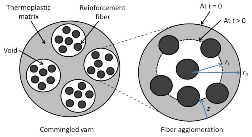
6.1.2. Autohesion Model
Figure 6 shows a schematic diagram of the autohesion or healing process for the
consolidation of thermoplastic polymers. When a new thermoplastic layer is brought into
intimate contact with the substrate and heat is applied, polymer chain inter-diffusion across
the interface can occur. Over time, enough polymer chain inter-diffusion take place and the
interface becomes indistinguishable from the bulk polymer [74,75]. This results in strong
bonding between the thermoplastic layers. Autohesion can occur at temperatures above Tg
for amorphous thermoplastics and above Tm for semi-crystalline thermoplastics [80,81].
Figure 6. Polymer chain diffusion in the autohesion process.
The diffusion of polymer chains is modeled based on the reptation theory detailed
by De Gennes [82]. A polymer chain entangled with many other chains is restricted
to wriggling motions in a tube-like region at small time scales. At larger time scales,
the ends of the polymer chain can move away from the tube, forming minor chains.
Eventually, the polymer chain has a new position out of the initial tube. The time to
reach this state is the renewal or reptation time, tr [82,83]. The degree of autohesion,
Dah , is defined as the ratio of the interfacial bond strength to the fracture strength of the
virgin thermoplastic polymer. Kim and Wool considered the interfacial bond strength as a
function of the length of minor chains through the interface [83]. For time t < tr , Dah was
found to be proportional to t1/4 and M4/3 , where M is the molecular weight of the polymer.
Yang and Pitchumani proposed an autohesion model for non-isothermal condition [80].
Bonding at the interface is dependent on the critical entanglement molecular weight, MC .
MC is a function of the number of monomers, the polymer chain length, the monomer
weight, the number of C-C bonds per monomer, the bond length and the characteristic
ratio [84]. For thermoplastic polymers with molecular weight M > 8MC , the maximum
bond strength is reached at the welding time, tw with tw < tr . This is the case for most
engineering thermoplastic polymers. The degree of autohesion for non-isothermal healing
is given by Equation (8) [80]:
Z t
1
1 4
Dah (t) = dt (8)
0 tw (T )
where T is the temperature. For polymers with M < 8MC , the welding time is the same as
the reptation time ( tw = tr ). tw is dependent on T, with their relationship described by an
Arhennius law [80]. At higher temperatures, the polymer chains can diffuse more easily,
leading to shorter welding times.Polymers 2021, 13, 1951 12 of 29
6.1.3. Bonding Model
For the bonding of FRTP prepreg tapes, intimate contact has to occur before autohesion
can take place. Yang and Pitchumani described the bonding process as the healing of
incremental intimate contact areas. The degree of bonding, Db , is thus given as shown in
Equation (9) [85]:
Z t
b dDic (t)
Db (tb ) = Dic (0)·Dah (tb ) + Dah (tb − t)· dt (9)
0 dt
where tb is the total bond time, Dic (0) is the initial intimate contact area and ( tb − t) is the
time available for autohesion for an incremental intimate contact area. For cases where
the time required to achieve full intimate contact is much larger than the time required for
autohesion (e.g., as reported in [41]), Db is taken to be the same as Dic .
6.2. Consolidation of Commingled Yarns
The consolidation process of FRTP composites made from commingled yarns involves
the impregnation of fiber bundles by the thermoplastic matrix, in addition to the intimate
contact and autohesion of the thermoplastic. The impregnation step is usually the lim-
iting step [86], thus researchers have focused on the impregnation step in studying the
consolidation of commingled yarns.
Klinkmuller et al. developed an impregnation model for commingled yarns [87].
The commingled yarns are modeled as consisting of several fiber agglomerations of the
same size surrounded by the thermoplastic matrix (Figure 7). Consolidation is achieved
when the voids in the fiber agglomerations are filled by the matrix.
Figure 7. Cross section of commingled yarn modeled as a group of fiber agglomerations.
The Darcy’s law is used to describe the flow of the thermoplastic polymer through the
reinforcement fibers (functioning as a porous bed). For the transverse permeability through
the reinforcement fibers, the model presented by Gutowski et al. is used for cases with
high fiber volume content [88]. The impregnation time, t, required to reach a penetration
length, z, is given by Equation (10) [87]:
2µkzz z2 V a
Vf + 1
t= q 3 (10)
Va
r2f (pa − p0 ) V − 1
f
where:
• µ is the viscosity of the thermoplastic matrix dependent on the temperature through
an Arhennius law,
• Va is maximum fiber volume content (0.83 for carbon fibers [88]),
• Vf is the pressure dependent fiber volume content,Polymers 2021, 13, 1951 13 of 29
• rf is the radius of the reinforcement fiber,
• pa is the applied pressure,
• p0 is the atmospheric pressure, and
• kzz is the transverse permeability constant through the fibers.
For fiber agglomerations with circular cross sections (Figure 7), z is related to void
content, Xv , by Equation (11) [87]:
v
u X A
z = r0 − t
u v t (11)
πn 1 − Vf
where r0 is the radius of the fiber agglomeration, n is the number of fiber agglomerations
in the yarn and At is the total cross sectional area of the commingled yarn.
For fiber agglomerations with rectangular cross sections, the relationship between z
and Xv is given by Ye et al. [89], and also reported by Friedrich [32]. The relationship is
shown in Equation (12) [32,89]:
h0 1 − Vf − h1(z,0) Xv
z= (12)
1 − Vf ( 1 − Xv )
where h0 is the half height of the fiber agglomeration and h1(z,0) is the half height of the
total agglomeration, which includes the surrounding thermoplastic matrix, at time, t = 0.
The models (Equations (10)–(12)) can give satisfactory predictions for the impregnation
time required to achieve a target void content, but require many parameters determined
through experiments and empirical data fitting. In particular, the experiments required to
determine kzz is difficult to carry out [88].
Another model for the consolidation of commingled fibers is proposed by Bernet et al. [33,86].
The commingled yarn is also modeled as a group of fiber agglomerations, but the agglomerations
can have different sizes. The fiber volume fraction, Vf , is assumed to be constant after some
pressure is applied, thus permeability of the fiber bed, KP , is also constant. The position of the
thermoplastic flow front, ri , is used in the model (Figure 7). For unimpregnated fiber agglomera-
tions, the voids are considered open pores. As impregnation progresses, the thermoplastic matrix
connects the fibers causing air to be trapped in the voids. At this stage, the voids are considered
closed pores. A parameter, rc , is defined such that when ri ≥ rc , voids are open pores, and when
ri < rc , voids are closed pores. Using the Darcy’s law, the relationship between ri and time, t, is
given by Equation (13) [33,86]:
µ 1 − Vf
" #
r2i R2i r2i R2i
ri Ri
∆t = ln − ln − + (13)
KP Pa + Pc − Pg (ri ) 2 r0 2 r0 4 4
where Pc is the capillary pressure (defined as positive when enhancing flow), Pa is the
applied pressure, Ri is the thermoplastic flow front before the time increment, ∆t, and µ
is the viscosity of the thermoplastic matrix. Pg (ri ) is the internal void pressure given by
Equation (14) [33,86]:
2
rc
Pg (ri ) = P0 for ri ≥ rc Pg (ri ) = P0 for ri < rc (14)
ri
where P0 is the ambient pressure in the fiber agglomeration before void closing. Equa-
tion (13) is obtained through numerical integration where Pg (ri ) is assumed to be constant
over the time increment, ∆t. Total impregnation time for ri < rc is the sum of the time
increments. Pc is small compared to Pa and can usually be neglected [86].
The fiber agglomerations are grouped according to the agglomeration size. For ag-
j j
glomeration size group j, Na is the number of agglomerations in the group and ri isPolymers 2021, 13, 1951 14 of 29
the thermoplastic flow front. The void content of the yarn, Xv , is then computed using
Equation (15) [33,86]:
j j2
∑nj=1 πNa ri 1 − Vf
Xv = j j2
(15)
At + ∑nj=1 πNa ri 1 − Vf
where n is the number of agglomeration sizes and At is the cross section area of a fully
consolidated yarn. The number of agglomerations and their sizes can be determined from
microscopic observations of the commingled yarn. For the determination of KP , Bernet et al.
used Gebart’s model [90] given in Equation (16):
s !2.5
Vf ,max
KP = C1 −1 R2f (16)
Vf
where C1 is a constant, Vf ,max is the maximum fiber volume fraction corresponding to
zero permeability and Rf is the fiber radius. C1 and Vf , max are related to the fiber ar-
rangement. Bernet et al. used their model to study the consolidation of carbon/PA12
commingled fibers [33,86]. The authors showed that the model is applicable for processes
with consolidation times in the order of 1 min, 0.1 min and 10 s [33].
Thomann and Ermanni expanded on the model proposed by Bernet et al. [34]. The au-
thors used a logarithmic normal distribution to better describe the fiber distribution within
a commingled yarn with good blending. The frequency of occurrence for a fiber agglomer-
ation of size j is given by Equation (17) [34]:
j 2
ln N − ζ ∗
j
1 1 f
φ Na = √ j
exp− (17)
n 2 s
s 2π ∑j=1 Na
j
where Nf is the number of fibers in the agglomeration of size group j, s2 is the variance
j
and ζ ∗ is the predictand of ln Nf . The parameters defining the fiber distribution are
estimated from microscopic observations of the comminged yarn. Thomann and Ermanni
used the model to study the stamp forming of FRTP composite components made from
carbon/PA12 and carbon/poly(butylene-terephthalate) (PBT) commingled yarns [34].
6.3. Consolidation of Powder Impregnated Fibers
Similar to commingled fibers, the impregnation of the reinforcement fibers by the
thermoplastic matrix is the limiting step in the consolidation of powder impregnated fibers.
Ye et al. developed a model to study the consolidation of powder impregnated
fibers [91]. The thermoplastic flow is assumed to occur only in the radial direction (trans-
verse flow through the fiber bed). Therefore, the impregnation process is modeled similar
to that of commingled yarns (as reported in [32,87,89]) with a representative fiber agglom-
eration or tow. Using Darcy’s law, the time, t, required for the thermoplastic flow front to
reach a position ri is given by Equation (18) [91]:
" 2 #
µr20 ri 2 ri r
t= 2 ln +1− i (18)
4KP (pa − p0 ) r0 r0 r0
where r0 is the radius of the fiber tow, p0 is the pressure within the tow (taken as atmo-
spheric pressure), pa is the applied pressure, KP is the permeability and µ is the viscosityPolymers 2021, 13, 1951 15 of 29
of the thermoplastic matrix. The void content, Xv , can be calculated from ri using Equa-
tion (19) [91]:
2
πr20 rr0i 1 − Vf − Vmp
Xv = 2 (19)
πr20 1 + rr0i 1 − Vf − Vmp
where Vf is the fiber volume fraction and Vmp is the volume fraction of the matrix powder.
Ye et al. used the Carman-Kozeny equation to determine KP [91]. The authors reported
good correlation between the model predictions and experimental results in their study on
glass/PP composites [91].
Steggal-Murphy et al. used a similar model to that of Ye et al. [92]. In their study,
Steggal-Murphy et al. investigated the consolidation of an FRTP composite made with
glass fiber fabric as reinforcement and HDPE powders as matrix. A rectangular cross
section was used to model a powder impregnated fiber bundle. The deformation of the
fiber tow is assumed to be negligible. The authors used an empirical approach to determine
the ratio of K/µ, where K is the permeability of the fiber bundle and µ is the viscosity
of the thermoplastic. The consolidation was divided into two stages, namely the ramp
stage where pressure is increased to a setpoint and the dwell stage where pressure is held
constant. The authors reported that the model gave good predictions of the laminate void
content for consolidation carried out at low applied pressure (0.345 MPa). However, for
consolidation performed at high pressure (0.690 MPa), the void content is overestimated
by the model. This is because the effects of fiber tow deformation become significant when
the applied pressure is high [92].
Connor et al. used a different approach in their impregnation model for powder
impregnated fibers [93]. During consolidation, the thermoplastic matrix powders melt
and form resin bridges between the reinforcement fibers. The impregnation process is
modeled as the thermoplastic flow along the length of the fibers (axial flow), as shown
in Figure 8. The distance between the reinforcement fibers, d, decreases as impregnation
occurs. The assumptions made by the authors include: (i) transverse thermoplastic flow
through the fibers is negligible compared to the axial flow, (ii) the center of the molten
matrix powder is fixed and its volume is constant, and (iii) all of the resin bridges can be
modeled using the same geometry.
Figure 8. Model of resin bridge between fibers during the consolidation of powder impreg-
nated fibers.
For the consolidation process, the applied pressure (Pa ) is counteracted by the capillary
pressure (PC ), viscous pressure from the thermoplastic (Pv ) and the spring-like pressure
from the fiber bundle (Ps ). Ps is due to the compression of the fiber bundle as reportedPolymers 2021, 13, 1951 16 of 29
by Gutowski et al. [88]. Connor et al. applied the Hagen-Poiseuille equation to relate the
thermoplastic flow to Pv . The flow rate is then expressed as shown in Equation (20) [93]:
!4
Rf 6 Vm L 4
d l 27
= (Pa − Ps − Pc ) (20)
dt L 128µ Rm Vf l
where l is the time dependent thermoplastic half length (Figure 8), L is the half length of the
molten thermoplastic powder when consolidation is completed (l = L at full consolidation),
Rf is the radius of the reinforcement fiber, Rm is the thermoplastic powder radius, µ is
the thermoplastic viscosity, Vf and Vm are the final fiber and matrix volume contents.
Pc is usually much smaller than Pa and thus can be neglected. For the carbon/PEEK and
carbon/PEI composites studied, the authors also found that Ps was insignificant compared
to Pa . In cases where Pc and Ps are small, the time to reach full consolidation, t1 , can be
determined from Equation (21) [93]:
4 !6
Vf
t1 Pa 128 Rm
= (21)
µ 135 Vm Rf
For cases where Pc or Ps is comparable to Pa , Equation (20) needs to be integrated
numerically. In the model, the effect of different wetting behaviors in different material
systems is absent as Pc is neglected. However, the authors stressed that the wetting behav-
iors are important for the fiber-matrix bonding and need to be taken into consideration in
studying the consolidation of powder impregnated fibers [93].
7. Modeling Crystallization and Other Aspects of FRTP In Situ Consolidation
For FRTP with semi-crystalline thermoplastic matrices, the morphology of the ther-
moplastic affects the mechanical properties of the composite. Factors affecting the mor-
phology include the degree of crystallinity, spherulite size and crystalline orientation [8].
Many researchers use the degree of crystallinity as a means of studying the morphol-
ogy [51,53,94,95]. For PEEK, tensile strength and stiffness increases with increasing crys-
tallinity but fracture toughness decreases at the same time [8]. Therefore, the consolidation
process, especially the cooling rate, needs to be controlled properly to achieve the desired
crystallinity [8,69].
Ozawa derived an expression for non-isothermal crystallization given in Equation (22) [96]:
dT
log[− ln(1 − cr )] = log X(T ) + n log (22)
dt
where cr is the relative crystallinity, T is the temperature, t is time, X(T ) is the cooling
function, and n is a constant. X(T ) and n can be obtained by analyzing differential scanning
calorimetry (DSC) curves of the crystallization process occurring at different cooling rates.
The crystallinity, ca , is related to cr through Equation (23) [76]:
ca H
= T (23)
cr HU
where HT is the total heat of crystallization at a given cooling rate and HU is the theoretical
ultimate heat of crystallization for the thermoplastic. Researchers have used the Ozawa model
to simulate the crsytallization process of FRTP composites such as carbon/PEEK [76,97]. For
the APC-2 carbon/PEEK composite, n = 0.8, X(T ) = exp(−0.037 T + 11.3), and the ratio
HT /HU can be calculated using HT /HU = −0.03 ln(dT/dt) + 0.42 [76,97].
Another non-isothermal crystallization model was derived by Choe and Lee [98].
The model is based on phase transition kinetics formulated by Tobin, which includesPolymers 2021, 13, 1951 17 of 29
the growth site impingement phenomena [99–101]. The non-isothermal crystallization
expression derived by Choe and Lee is given in Equation (24) [98]:
. 0
3ψ1 Tm
α(t) = κ1 exp − 3ERT
d
exp − 0 −T t2 [1 − α(t)]2
T (Tm )
0 (24)
(3ψ1 +ψ2 )Tm
+κ2 exp − 4E RT
d
exp − 0 −T
T ( Tm )
Rt
·[1 − α(t)]2 0 (t − ω )2 [1 − α(ω )]dω
0 is the equilibrium
where α(t) is the relative crystallinity at time t, T is the temperature, Tm
melting temperature, Ed is the activation energy of diffusion of crystallization segments
across the phase boundary, ψ1 is a constant related to the free energy of formation of
a critical nucleus, ψ2 is a constant related to the free energy of formation of a growth
embryo, κ1 and κ2 are kinematic parameters. The expression is applicable for crystallization
through the formation 3D spherulites. The first part of Equation (24) describes the rate of
crystallization through heterogenous nucleation and growth, while the second part gives
the rate of crystallization through homogenous nucleation and growth. Choe and Lee
varied the temperatures and cooling rates in DSC to control the crystallization mechanisms
of PEEK. The values of Tm 0 , E , κ , κ , ψ , ψ for PEEK were then determined analyzing the
d 1 2 1 2
DSC results with the use of regression methods [98].
In a study on AFP with laser ISC, Sonmez and Hahn used Choe and Lee’s model to sim-
ulate the crystallization in the FRTP tape in the cooling phase [61]. For the crystal melting
process occurring in the heating phase, the model proposed by Maffezzoli et al. [102] was
used. From the model, the crystallinity at time t, ca (t), is given by Equation (25) [61,102]:
Z t 2
ca (t) = ca (tinit ) 1 − 0.5 Kdt (25)
tinit
where tinit is the initial time and K is given by K = K0 exp(−Eam /RT ). For APC-2 com-
posite, the constant K0 = 5.05 × 1031 s−1 and the activation energy for melting, Eam , is
397 kJ/mol [72,77]. Sonmez and Hahn’s approach was also used by Song to simulate the
crystallization process in FW of carbon/PEEK with ISC using hot gas torch [72].
Gordnian used a ‘semi model-free’ approach in modeling the crystallization and melt
kinetics of the carbon/PEEK composite [103]. Multiple isothermal and non-isothermal
DSC experiments were carried out. Using the DSC results, Gordnian plotted the ‘iso-
conversional’ graphs for the crystallization rate to study its dependence on crystallinity
and the temperature. An empirical model was then introduced with the model parameters
determined through experimental data fitting. For cases where the crystallinity is below
0.001, an induction time need to be calculated to determine the onset of the crystallization
process. Gordnian also studied the melt kinetics using the same procedure. Two peaks
were observed in the melting DSC experiments. The author deduced that recrystallization
and melting occurred simultaneously in the process, resulting in the two peaks observation.
A master melt curve was then obtained using the DSC results and the results calculated
from the crystallization model. The combined model was shown to give good predictions
for the crystallinity in isothermal and non-isothermal crystallizations and melting.
Besides crystallinity, researchers have also modeled other aspects of FRTP composites
fabricated using AFP and FW with ISC. Schlottermuller et al. studied the thermal residual
stresses in glass/PP specimens made using FW with hot gas torch ISC [104]. The thermal
expansion coefficients are included in the stress-strain submodel to calculate the stress
distributions across the composite layers. Dedieu et al. used the same approach to study
the residual stresses in carbon/PEEK composites fabricated using FW with laser ISC [105].
Nam and Seferis presented a model for the degradation kinetics in thermoplastic compos-
ites [106]. The degradation model is defined by a rate constant, k(T ), and a conversion
dependence function, f (α). The temperature dependence of k(T ) is described by an Arrhe-
nius expression. For f (α), the effects of different reaction mechanisms are included usingPolymers 2021, 13, 1951 18 of 29
weighting factors. Nam and Seferis obtained the kinetic parameters for the degradation of
PEEK from thermogravimetric analysis (TGA) experiments and showed that the model
gave good predictions. The model developed by Nam and Seferis was adopted by Sonmez
and Hahn in their studies on AFP with ISC [61,107].
8. Studies on Factors Affecting In Situ Consolidation Quality
Many researchers have carried out experimental and numerical studies on the fab-
rication of FRTP composites using AFP and FW with ISC. Many researchers compared
the composite components fabricated using AFP and FW with components fabricated
using more established methods for FRTP composites, such as compression molding and
autoclave. The quality of the fabricated component is evaluated by its void content as well
as mechanical properties measured from tests such as the short beam shear (SBS) test, peel
tests, bending tests and delamination tests (such as the double cantilever beam (DCB) test).
Comer et al. compared the mechanical performance of carbon/PEEK laminates
fabricated using AFP with laser ISC with laminates fabricated using autoclave [51]. Car-
bon/PEEK prepreg tapes with a width of 12 mm were used in the AFP process. For the
laminates fabricated using autoclave, wide carbon/PEEK tapes (width of 150 mm) were
used to make the pre-forms by hand lay-up. The pre-forms were then sealed in a high
temperature vacuum bag and consolidated in an autoclave. The specimens fabricated
using the AFP process have higher interlaminar fracture toughness compared to the au-
toclave specimens. However, the AFP specimens have lower crystallinity (17.6%) than
the recommended level (33%). This led to the specimens having lower flexural strength,
interlaminar shear strength, and open-hole compression strength compared to autoclave
specimens (crystallinity 40%). The authors suggested the high cooling rate and insufficient
through thickness heating as two possible causes for the low crystallinity in the specimens
fabricated using laser ISC.
Hoa et al. studied the fabrication of carbon/PEEK laminates using AFP with ISC using
a hot gas torch [48]. Carbon/PEEK prepreg tapes were used in the study. The mechanical
properties of carbon/PEEK laminates consolidated using the autoclave method from
literature were used for comparison. The authors reported increased fiber waviness in the
laminates fabricated using AFP compared to laminates fabricated using autoclave, leading
to worse compressive strength in the AFP laminates. This is due to excessive compressive
pressure from the rigid compaction roller. Another problem inherent to AFP with ISC is
the uneven temperature distributions in the through thickness direction of the laminate,
causing warpage. The authors recommended heating the mandrel or tool above the Tg of
the thermoplastic matrix to circumvent the warpage problem.
Stokes-Griffin and Compston studied various aspects of the AFP process with laser
ISC for carbon/PEEK prepreg tapes [52,79]. Laminates fabricated using a lower line speed
(100 mm/s) exhibited better fiber-matrix bonding compared to laminates fabricated using
a higher line speed (400 mm/s). The authors attributed this to the higher crystallinity
in the laminates fabricated at 100 mm/s. For the compaction roller, a deformable roller
(silicone roller) resulted in better consolidation compared to a rigid roller (brass roller).
This is due to the large laser shadow produced by the rigid roller. For the modeling of the
consolidation process, the authors showed that the temperature threshold for autohesion
of PEEK to occur is Tg instead of Tm if the PEEK is completely melted at the heating phase.
Doan and Mertiny studied the creep response of FRTP components fabricated using
FW with hot air blower ISC [108]. Glass/HDPE prepreg tapes with a width of 49 mm were
used. Two batches of specimens were fabricated. For batch 1, the heater setting of 400 ◦ C
was used for the first 7 layers and 420 ◦ C was used for layers 8 to 10. For batch 2, the heater
was set to 400 ◦ C for the first 4 layers, 420 ◦ C for layers 5 to 8, and 440 ◦ C for layers 9 to
10. The batch 2 specimens exhibited better fiber packing and greater resistance to creep.
The authors explained that the higher processing temperatures in the batch 2 specimens
led to higher crystallinity, thus resulting in improved creep resistance.You can also read