Ridge Gap Waveguide Based Liquid Crystal Phase Shifter - TUprints
←
→
Page content transcription
If your browser does not render page correctly, please read the page content below
Received April 9, 2020, accepted April 20, 2020, date of publication April 22, 2020, date of current version May 8, 2020.
Digital Object Identifier 10.1109/ACCESS.2020.2989547

Ridge Gap Waveguide Based Liquid
Crystal Phase Shifter
MATTHIAS NICKEL 1 , (Graduate Student Member, IEEE),
ALEJANDRO JIMÉNEZ-SÁEZ 1 , (Student Member, IEEE),
PRANNOY AGRAWAL 1 , (Graduate Student Member, IEEE),
AHMED GADALLAH 2 , (Member, IEEE), ANDREA MALIGNAGGI 2 ,
CHRISTIAN SCHUSTER 1 , (Student Member, IEEE),
ROLAND REESE 1 , (Graduate Student Member, IEEE),
HENNING TESMER 1 , (Graduate Student Member, IEEE),
ERSIN POLAT 1 , (Student Member, IEEE), DONGWEI WANG 1 ,
PETER SCHUMACHER 1 , (Graduate Student Member, IEEE),
ROLF JAKOBY 1 , (Member, IEEE), DIETMAR KISSINGER 3 , (Senior Member, IEEE),
AND HOLGER MAUNE 1 , (Senior Member, IEEE)
1 Institute   of Microwave Engineering and Photonics, Technische Unversität Darmstadt, 64283 Darmstadt, Germany
2 IHP–Leibniz-Institut     für innovative Mikroelektronik, Im Technologiepark 25, 15236 Frankfurt (Oder), Germany
3 Institute   of Electronic Devices and Circuits, Ulm University, 89081 Ulm, Germany
Corresponding authors: Matthias Nickel (nickel@imp.tu-darmstadt.de) and Alejandro Jiménez-Sáez (jimenez@imp.tu-darmstadt.de)
This work was supported by the German Research Foundation within the DFG Project HyPAA under Grant 320392473 and the Open Access
Publication Fund of Technische Universität Darmstadt. Matthias Nickel and Alejandro Jiménez-Sáez contributed equally to this work.

   ABSTRACT In this paper, the gap waveguide technology is examined for packaging liquid crystal (LC) in
   tunable microwave devices. For this purpose, a line based passive phase shifter is designed and implemented
   in a ridge gap waveguide (RGW) topology and filled with LC serving as functional material. The inherent
   direct current (DC) decoupling property of gap waveguides is used to utilize the waveguide surroundings as
   biasing electrodes for tuning the LC. The bed of nails structure of the RGW exhibits an E-field suppression
   of 76 dB in simulation, forming a completely shielded device. The phase shifter shows a maximum figure
   of merit (FoM) of 70 ◦ /dB from 20 GHz to 30 GHz with a differential phase shift of 387◦ at 25 GHz. The
   insertion loss ranges from 3.5 dB to 5.5 dB depending on the applied biasing voltage of 0 V to 60 V.

   INDEX TERMS Liquid crystals (LC’s), tunable phase shifter, phased array, gap waveguide, bed of nails.

I. INTRODUCTION                                                                                   of a transmission line section combined with the functional
Nowadays, the development in communication is already                                             material. They do not require additional power like active or
driven by mobility/portability and data rate, which will be                                       ferrite based phase shifters [1], [2], nor complicated varactor
emphasized even more by future applications such as IoT,                                          designs like loaded line or reflection type phase shifters [3].
industrial digitization, 5G or autonomous driving. For con-                                       Other advantages are their compactness and robustness com-
cepts like cognitive radio or high data rate wireless commu-                                      pared to electromechanical approaches [4]. Further, a contin-
nication, flexible filtering in the frequency or spatial domain                                   uous tuning of the phase shift is possible.
is required. This poses additional challenges for the radio                                          The choice for the functional material fell on LC since it
frequency (RF) frontend design. Here, varactors and phase                                         provides low losses especially for frequencies above 20 GHz
shifters are a key component to realize tunable filters and                                       up to the THz range [5], which makes it a promising func-
beamsteering antennas.                                                                            tional material for future communication systems operating
   This work focuses on a line-based passive phase shifter,                                       in the millimeter wave range and above. The working princi-
utilizing a functional material. These kind of phase shifters                                     ple of LC is summarized in Fig. 1c. LC, being a mesophase
are appealing due to their ease of design: They consist only                                      material at room temperature, exhibits properties of a liquid
                                                                                                  and a crystal at the same time, including birefringence. The
    The associate editor coordinating the review of this manuscript and                           molecules of the used nematic mixture can be considered rod
approving it for publication was Weiren Zhu               .                                       shaped, whereas they exhibit no long-range spatial order but a

                        This work is licensed under a Creative Commons Attribution 4.0 License. For more information, see https://creativecommons.org/licenses/by/4.0/
VOLUME 8, 2020                                                                                                                                                           77833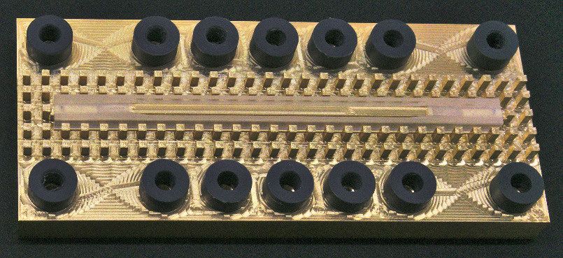
M. Nickel et al.: Ridge Gap Waveguide Based Liquid Crystal Phase Shifter

                                                                            to mode coupling of the TE10 mode into the biasing elec-
                                                                            trodes, where different kind of Stripline modes can be excited.
                                                                            Hence, the insertion loss is increased and the performance
                                                                            decreases (from FoM = 200 ◦ /dB to FoM = 150 ◦ /dB, [8]).
                                                                            To mitigate this effect, certain care has to be taken in the
                                                                            electrode design. For example, stepped impedance filters can
                                                                            be integrated into the electrodes to avoid mode coupling [9].
                                                                            However, a complete suppression of these unwanted modes,
                                                                            especially at higher frequencies, is difficult in practice,
                                                                            mainly due to the small feature size close to or even beyond
                                                                            manufacturing tolerances.
                                                                               In order to avoid these difficulties in electrode design and
                                                                            integration, the basic idea of this work is to utilize the waveg-
FIGURE 1. Conceptual evolution of the LC ridge gap phase shifter: (a)       uide surroundings itself as electrodes as depicted in Fig. 1b.
Cross section of a LC hollow waveguide phase shifter integrating four       For this, the waveguide is cut in half in its H-plane. In between
electrodes enabling full electric tuning of the LC. (b) A ridged hollow
waveguide with DC blocks in the side walls. Here, the enclosure of the      this cut, a component has to be introduced, which serves as
waveguide itself can act as electrodes for tuning. (c) Interaction of LC    a short for the RF wave and as a block for the applied DC
molecules with RF waves due to their birefringent property, depicted by
the Fresnel ellipsoid.
                                                                            voltage. One type of waveguide, which exhibits exactly these
                                                                            desired properties, called gap waveguide, has been studied
                                                                            intensively in the last few years [10]–[14]. It consists of two
                                                                            parallel metal plates, where one of the plates is patterned to
certain directional order, which is macroscopically described
                                                                            form a metamaterial surface, called bed of nails in this case,
by the director vector nE, see Fig. 1c. Associated with the
                                                                            which prevents wave propagation in its stop band, see Fig. 2.
director, the birefringent property can be described by a
                                                                            With the help of the metamaterial pattern, an electromagnetic
Fresnel ellipsoid with a permittivity εk parallel to the direc-
                                                                            wave can be guided similar to a hollow waveguide but without
tor and a permittivity ε⊥ perpendicular to it. A transversal
                                                                            the necessity of an electrical contact between the waveguide’s
electromagnetic wave interacting with this kind of material
                                                                            side walls.
will experience any permittivity on the Fresnel ellipsoid, i.e.
                                                                               The aim of this work is to validate the applicability of
between ε⊥ and εk , depending on the tilt angle α between the
                                                                            the gap waveguide for a LC based phase shifter to ease
electric field vector EE and the director nE. The LC molecules’
                                                                            the electrode integration and to improve isolation. For this,
orientation can be controlled in three different ways: Mechan-
                                                                            a LC filled RGW was designed and fabricated, which will
ically, utilizing surface anchoring forces, magnetically and
                                                                            be described in more detail in the next section. To ease
electrically [6], where the LC will orient its molecules parallel
                                                                            the coupling design and to prevent tolerance issues during
to the field lines in order to minimize its free energy. In
                                                                            fabrication, this demonstrator was chosen to operate around
practical applications, usually electric tuning is used, often
                                                                            26 GHz
in combination with a mechanical pre-orientation by surface
anchoring. Magnetic tuning is mostly used for material char-
acterization and in test setups only due to its bulkiness and               II. DESIGN AND IMPLEMENTATION
power consumption.                                                          The bed of nails structure used in this work consists of peri-
   To compare the performance of different phase shifters, a                odic electric pins surrounding the desired waveguide. This
figure of merit (FoM) was previously introduced [7], which                  structure is patterned on one of the metallic plates, acting
relates the maximum differential phase shift achieved to the                as the bottom and side walls of the waveguide. The other
maximum insertion loss over the tuning states, described by                 plate is unpatterned, forming the top wall of the waveguide.
the tuning voltage Vbias .                                                  A gap is left between the top of the nails and the top plate,
                                                                            so that they are DC-decoupled. Thus, the lower plate and
                                  max {1Φ}                                  the upper plate can act as electrodes for aligning the LC
                                  Vbias
                        FoM =                                         (1)   vertically. Horizontal alignment is achieved in this design
                                   max {IL}
                                   Vbias                                    by utilizing surface anchoring forces at the top and bottom
                                                                            plate.
   The best performance so far (FoM = 200 ◦ /dB at
                                                                               The bed of nails structure realizes a high impedance sur-
fop = 30 GHz, [8]) is achieved with a magnetically biased
                                                                            face, which limits the electromagnetic wave propagation for
hollow waveguide topology. However, for the electric tun-
                                                                            frequencies between 14 GHz and 37 GHz, forming an elec-
ing of liquid crystals, a biasing circuitry, i.e. electrodes are
                                                                            tronic band gap. For this, the designed bed of nails has to
necessary to generate the quasi-static E-fields. In the case of
                                                                            comply the following conditions [10]:
rectangular waveguides, such electrodes need to be placed
inside the waveguide, so that the DC fields can interact with                 •    Nail height d, corresponds to the quarter-wavelength at
the LC, see in Fig. 1. The addition of these electrodes leads                      22 GHz, roughly at the center of the stop-band region.

77834                                                                                                                                      VOLUME 8, 2020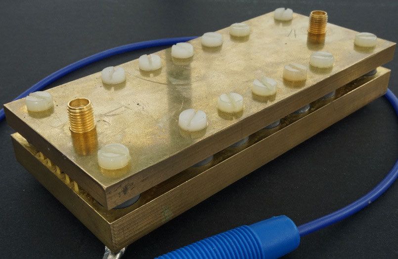
M. Nickel et al.: Ridge Gap Waveguide Based Liquid Crystal Phase Shifter
FIGURE 2. Schematic view of the RGW phase shifter including cross sections, a detailed view (X) of the capacitor section and the
corresponding dimensions.
TABLE 1. Properties of the used LC mixture GT3 23001 at room connectors, a linear taper reduces the ridge height. The ridge
temperature and f = 19 GHz (provided by Merck KGaA).
extends by λ/4 after the coax connector, where it is shorted
by the first pin of the bed of nails. Moreover, the inductive
nature of the connector-ridge interface is compensated by
introducing a disk capacitor in Rogers RT/duroid 6010 sub-
strate between the connector pin and the ridge (see Fig. 2).
Additionally, this capacitor serves as DC block between bot-
• Space between upper and lower plate h + d, corresponds tom plate and SMA connector pin.
to the half-wavelength at 40 GHz, determining the upper The upper plate and the lower plate are fabricated sep-
end of the stop-band region. arately by milling using Brass. The Rexolite container is
To ensure sufficient wave guidance and shielding, three rows pressed between top and bottom plate and additionally sealed
of nails are placed around the waveguide in a first design. using glue. PVC alignment rings are placed around the
However, later simulations (see Fig. 8) showed that two rows waveguide to ensure alignment between both plates, which
of nails are still sufficient for wave guidance and shielding, are then held together by Nylon screws. All separate parts
which was adapted to the final implementation in favor of except the top plate are shown in Fig. 3a. The assembled
fabrication simplicity and compactness. phase shifter including the top plate is depicted in Fig. 3b.
Since the alignment speed of LC depends on field-strength
and layer thickness, a ridge was introduced in the gap waveg- III. SIMULATIONS AND MEASUREMENTS
uide, reducing the distance between the lower and the upper The phase shifter is designed and simulated using CST Studio
plate to 0.2 mm for the LC section. The so designed RGW Suite and the fabricated prototype is measured using a vector
allows for the propagation of a quasi-TEM mode. network analyzer calibrated for a frequency range of 20 GHz
A LC container made of Rexolite is used to prevent LC- to 30 GHz.
leakage. This container extends from the input to the output For modelling the LC material inside CST Studio Suite, use
port as shown in Fig. 2. The length of the phase shifter part, is made of the tensor formula material model, which is fed by
i.e. the LC-cavity was chosen to enable a full 360◦ differential the permittivity and loss tangent tensor of the used GT3 23001
phase shift with the LC mixture GT3 23001 from Merck material (see Table 1). For a z-oriented LC director, the
KGaA (see Table 1). This LC is filled through two holes on permittivity tensor is described by
the upper plate, which are close to the end of the LC cavity.
εr,⊥
Female SMA thread-in connectors are used in the top plate 0 0
to connect the phase shifter to the measurement equipment. ε̄ = ε0 0 εr,⊥ 0 . (2)
To match the impedance of the LC region (14 ) to the 50 0 0 εr,k
VOLUME 8, 2020 77835M. Nickel et al.: Ridge Gap Waveguide Based Liquid Crystal Phase Shifter
TABLE 2. Design parameters.
where K11 denotes the elastic splay constant of the LC mix-
ture (see Table 1).
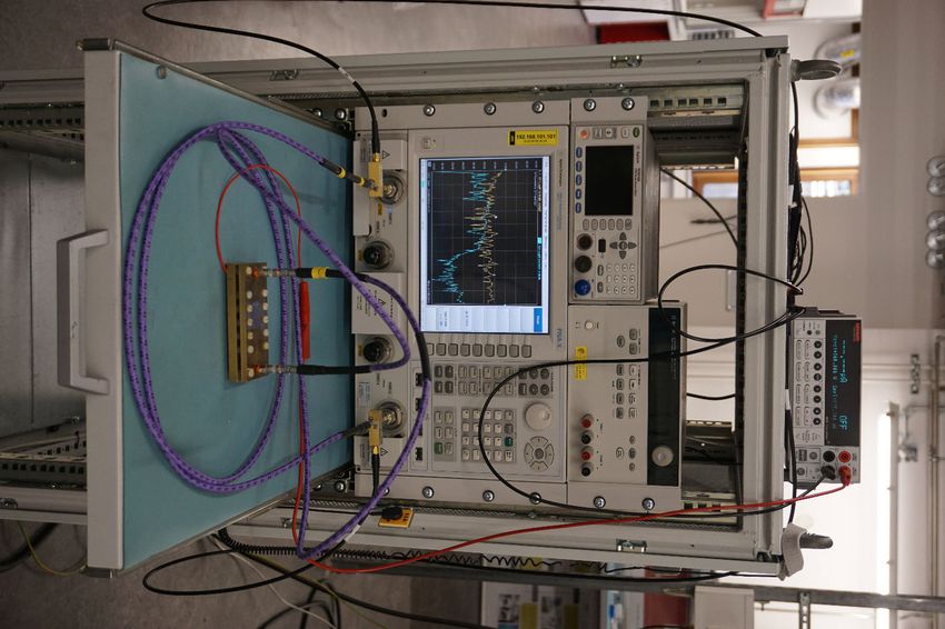
During measurement, the upper plate was grounded
FIGURE 3. Implementation of the RGW phase shifter: (a) Bottom plate
through external bias tees (see Fig. 4), which provide also
with the Rexolite container placed above the ridge and the PVC spacer additional protection in case the inherent DC block of the
rings placed in their grooves. (b) Assembled phase shifter with the top
plate fixed by nylon screws. The bottom plate is connected to the blue
phase shifter fails. The lower plate was connected to a 60 V
cable for applying the bias voltage. DC power supply for biasing the LC (see Fig. 3 and Fig. 4,
respectively).
Fig. 5 shows the scattering parameters. It can be seen that
Arbitrary orientation of the LC director is accounted by the matching is below −10 dB for a frequency range from
a coordinate transformation of the microwave field com- 21 GHz to 27 GHz, which is slightly better than predicted by
ponents into this LC director coordinate system and back. the simulation. This is caused by non-covered loss mecha-
Since wave propagation along the y-direction and LC director nisms, which also impact the insertion loss by roughly 2 dB.
alignment in the xz-plane is assumed (see Fig. 2), this coordi- Depending on the tuning state, the measured insertion loss
nate transformation can be carried out by rotation around the ranges from around 3.5 dB to 5.5 dB. The contribution of the
y-axis coaxial transitions and the linear taper to the overall insertion
ε = Ry (α)ε̄Ry (−α), (3) loss is roughly 1 dB, which was estimated using a supple-
mentary back to back assembly, revealing 0.5 dB and 1 dB of
where α is the tilt angle of the LC director with respect to insertion loss in simulation and measurement, respectively.
the z-axis (see Fig. 1c). Hence, the final permittivity tensor Despite of the 2 dB difference, the measured insertion loss
formulation for the CST Studio Suite model is given by conforms well to the simulated data up to 27 GHz, where
equation (6), as shown at the bottom of this page. The loss the measurement shows a large drop. This stems from the
tangent tensor formulation is derived analogously. used SMA thread-in connectors and accords to their specified
Since there is no possibility in CST Studio Suite to simulate frequency limit of 26.5 GHz. Here, higher order modes are
the LC directors orientation in dependence of the applied bias excited despite the fundamental mode. The result is mode
field, the model of the Freedericks cell was used to relate the mismatch and signal loss as observed. With appropriate con-
bias voltage Vbias to the tilt angle α by [15] nectors for higher frequencies (e.g. K-connectors), the pre-
2
Vbias ∂ 2α sented phase shifter should also be operable above 27 GHz as
π 2 cos α sin α − = 0, (4) depicted by the simulation, since the simulation model does
Vth2 ∂z2
not include the connectors.
with the threshold voltage From the linear phase and flat group delay depicted in
s Fig. 6, it can be concluded that the phase shifter exhibits no
K11 dispersion as can be expected for a purely line based phase
Vth = π , (5)
ε0 εr,k − εr,⊥ shifter.
εr,k sin2 (α) + εr,⊥ cos2 (α) 1
εr,k − εr,⊥ sin (2α)
0 2
ε = ε0 0 εr,⊥ 0 (6)
1
2 εr,k − εr,⊥ sin (2α) 0 εr,k cos2 (α) + εr,⊥ sin2 (α)
77836 VOLUME 8, 2020M. Nickel et al.: Ridge Gap Waveguide Based Liquid Crystal Phase Shifter
FIGURE 5. Measured and simulated scattering parameters of the RGW
phase shifter.
superstrate thickness has been altered between d = 3.4 mm
for comparison to the RGW and d = 0.5 mm for a more
FIGURE 4. Measurement setup with DC voltage source (top), network
analyzer with attached bias tees (middle) and RGW phase shifter practical use case and the corresponding line widths were
(bottom) attached to the bias tees. The DC voltage is supplied by the red adjusted to match the 14 line impedance of the RGW phase
cable to the bottom plate of the phase shifter. The ground reference is
supplied through the K-cables and the bias tees. shifter. Here, it can be observed that the implemented two row
RGW suppresses the E-field at 3λ0 by additional 43 dB com-
pared to a similar Microstrip setup and by additional 42 dB
To assess the aimed shielding property of the RGW, the compared to a similar Stripline setup, both on the Rogers
E-field in the cross section of the plane centered in the substrate. Assuming a thinner superstrate, the damping of the
LC layer was evaluated in simulation. With a perpendicular Microstrip setup increases but the suppression is still 18 dB
LC alignment, the worst case was assumed. The results are larger for the two row RGW. Contrary, the damping of the
depicted for a frequency of f = 25 GHz in Fig. 8 for the Stripline setup decreases and exhibits a 58 dB less damping
three and two row RGW. Here, one can observe a field compared to the RGW. Only the theoretical scenarios of air
damping of 79 dB at a distance of 3λ0 from the waveg- filled waveguides show the least difference to the RGW with
uides center for the RGW with three bed of nails rows. 8 dB fewer suppression, mainly caused by the lower dielectric
The two row RGW exhibits only a slightly less damping of constant of air, leading to a field displacement towards air.
76 dB, which justifies the choice for the implementation of This shielding property could also be confirmed during
the phase shifter. To compare these field damping results the measurements by moving a metallic perturber alongside
to common waveguides, the models of the Microstrip and the bed of nails structure, which had no influence on the
Stripline depicted in Fig. 7 have been simulated and evalu- measurement result.
ated analogously (see Fig. 8). For both waveguides, different A sweep over the bias voltage (see Fig. 9 and Fig. 10)
scenarios were simulated: A purely theoretic scenario with revealed a saturation of the phase variation at around
air as supporting superstrate material (i.e. the material above Vbias = 60 V, indicating complete alignment of liquid crystal
the actual waveguide’s LC substrate), since the bed of nail with the bias electric field. The maximum differential phase
section of the RGW is also mainly filled with air. For a more shift is shown in Fig. 9 by the red and blue curves for
practical scenario, a common microwave substrate (Rogers simulation and measurement, respectively. It takes roughly
RO4003C) has been assumed as superstrate. In both cases, the 7 s to achieve the parallel state. As already mentioned, there
VOLUME 8, 2020 77837M. Nickel et al.: Ridge Gap Waveguide Based Liquid Crystal Phase Shifter
FIGURE 8. Simulated normalized E-field of Microstrip, Stripline and RGW,
evaluated in the cross section of the plane centered in the LC layer of the
corresponding waveguide at f = 25 GHz for perpendicular LC alignment.
FIGURE 6. Measured and simulated phase and group delay of the RGW
phase shifter.
FIGURE 9. Measured and simulated differential phase shift of the RGW
FIGURE 7. Schematic view of the simulation models used to compare the phase shifter in dependence of frequency. The colored curves depict the
shielding properties of the RGW to Microstrip and Stripline, highlighting maximum phase shift in simulation and measurement, respectively. For
the varied parameter superstrate thickness d . For comparison, the clarity, the gray set of curves shows the voltage dependency only for the
corresponding line widths have been adjusted to match the 14 line measurement data.
impedance of the RGW phase shifter.
fbias = 1 kHz to prevent degradation of the LC mixture
are only two electrodes and there is no active way of re- due to electrochemical effects. In this case, the capacitance
aligning the LC, hence the phase shifter needs more than formed by the phase shifter and the corresponding equivalent
10 min to return to its unbiased state. Here, simulation and series resistance will affect the biasing power consumption.
measurement show close agreement and the goal of at least To assess these losses, a low frequency simulation was per-
360◦ of differential phase shift is accomplished. formed and the capacitance of the built phase shifter was
The FoM for the phase shifter as defined by (1) is shown measured. For the biasing scenario, a maximum bias with
in Fig. 11. Due to the 2 dB higher insertion loss in the Vbias = 60 V (peak) was assumed. The simulated admit-
measurement, the measured FoM is roughly 30 ◦ /dB lower tance is Y = 138 × 10−21 S + j516 nS which translates
than predicted by the simulation, exhibiting a maximum of to a capacitance of C = 82 pF and an equivalent series
70 ◦ /dB at 25 GHz. resistance of ESR = 518 n, leading to ohmic losses of
In the presented measurement, the phase shifter has been P = 248 × 10−18 W and hence being practically negligible.
biased by a DC electric field. Despite the current necessary The measured capacitance was almost twice the simulated
to load the capacitance between the top and bottom plate of with C = 160 pF due to the extended top and bottom plates
the phase shifter, no additional power is required to bias the for the mechanical fixation. The equivalent series resistance
LC. However, in a practical application, the LC will be biased was not measurable. Table 3 summarizes the simulated and
with a low frequency alternating current (AC) field of around measured results including the reactive power and current,
77838 VOLUME 8, 2020M. Nickel et al.: Ridge Gap Waveguide Based Liquid Crystal Phase Shifter
TABLE 4. Comparison of different LC based phase shifters according to
their FoM and size.
FIGURE 10. Measured and simulated differential phase shift of the RGW
phase shifter in dependence of biasing voltage Vbias and director tilt
angle α at f = 25 GHz.
for LC biasing directly from the waveguide surroundings,
eliminating the need for a specific electrode design. A ridge
was introduced to further reduce the LC cavity height to
0.2 mm. The capacitive coaxial coupling of this ridge gap
waveguide additionally acts as DC block for the RF feed,
eliminating the need for external bias tees. To the author’s
best knowledge, this is the first time that such a device was
implemented.
The measurement of this demonstrator revealed a differ-
ential phase shift of 387◦ at 25 GHz, with an insertion loss
ranging from 3.5 dB to 5.5 dB depending on the tuning state.
Here, the maximum FoM achieved is 70 ◦ /dB (see (1)),
which is comparable to other similar phase shifter topologies
like ridged hollow waveguide [16] or inverted Microstrip
FIGURE 11. Measured and simulated FoM of the RGW phase shifter. lines [17], but cannot compete with hollow waveguide [8] or
sub wavelength fiber [18] topology. A more comprehensive
TABLE 3. Simulated and measured biasing capacitance of the RGW phase comparison with other LC based phase shifters is given in
shifter and the corresponding loading current and apparent loss for a full Table 4. Fig. 12 further condenses the data from Table 4 by
biasing of Vbias = 60 V (peak) at fbias = 1 kHz.
comparing the achieved FoM versus the electrical size of the
phase shifters. Here, it is apparent that, although achieving a
reasonable FoM, the realized RGW phase shifter is still quite
bulky.
Apart from its size, the proof of concept here presents the
promising potential of gap waveguides for packaging LC in
tunable microwave components. The inherent DC decoupling
which has to be provided to the phase shifter for full bias. For eases the biasing network and electrode design. Attenuating
the built phase shifter a loading current of Ibias = 60.3 µA the E-field by 76 dB, the bed of nail structure not only pre-
and hence a reactive power of Q = 1.81 mvar needs to be vents the excitation of parallel plate modes, but also shields
provided for full phase shift. the RGW laterally without the need for via placing in the
LC layer. Further, the top and bottom metal layer act as RF
IV. CONCLUSION ground, shielding the device also in a multilayer setup and
This paper examines the applicability of gap waveguides for making integration easier.
LC-based electrically-tunable phase shifters. For this pur- The loading current and necessary reactive power to
pose, a proof of concept demonstrator was implemented oper- fully bias the presented phase shifter was assessed to
ating around 26 GHz. Hereby, the gap waveguide’s inherent Ibias = 60.3 µA and Q = 1.81 mvar, respectively. This
property of DC decoupling is utilized to form the electrodes comparatively small current might sum up in the application
VOLUME 8, 2020 77839M. Nickel et al.: Ridge Gap Waveguide Based Liquid Crystal Phase Shifter
[8] A. Gaebler, F. Goelden, A. Manabe, M. Goebel, S. Mueller, and R. Jakoby,
‘‘Investigation of high performance transmission line phase shifters based
on liquid crystal,’’ in Proc. Eur. Microw. Conf. (EuMC), Sep. 2009,
pp. 594–597.
[9] C. Weickhmann, N. Nathrath, R. Gehring, A. Gaebler, M. Jost, and
R. Jakoby, ‘‘A light-weight tunable liquid crystal phase shifter for an
efficient phased array antenna,’’ in Proc. Eur. Microw. Conf., Oct. 2013,
pp. 428–431.
[10] P.-S. Kildal, E. Alfonso, A. Valero-Nogueira, and E. Rajo-Iglesias, ‘‘Local
metamaterial-based waveguides in gaps between parallel metal plates,’’
IEEE Antennas Wireless Propag. Lett., vol. 8, pp. 84–87, 2009.
[11] A. Jimenez Saez, A. Valero-Nogueira, J. I. Herranz, and B. Bernardo,
‘‘Single-layer cavity-backed slot array fed by groove gap waveg-
uide,’’ IEEE Antennas Wireless Propag. Lett., vol. 15, pp. 1402–1405,
2016.
[12] A. Vosoogh, A. Haddadi, A. U. Zaman, J. Yang, H. Zirath, and A. A. Kishk,
‘‘W -band low-profile monopulse slot array antenna based on gap waveg-
uide corporate-feed network,’’ IEEE Trans. Antennas Propag., vol. 66,
no. 12, pp. 6997–7009, Dec. 2018.
[13] M. Ferrando-Rocher, J. I. Herranz-Herruzo, A. Valero-Nogueira,
B. Bernardo-Clemente, A. U. Zaman, and J. Yang, ‘‘8 ×8 ka-band
dual-polarized array antenna based on gap waveguide technology,’’ IEEE
Trans. Antennas Propag., vol. 67, no. 7, pp. 4579–4588, Jul. 2019.
[14] M. Baquero-Escudero, A. Valero-Nogueira, M. Ferrando-Rocher,
FIGURE 12. FoM versus electrical size for different LC based phase B. Bernardo-Clemente, and V. E. Boria-Esbert, ‘‘Compact combline filter
shifters and the presented RGW phase shifter. embedded in a bed of nails,’’ IEEE Trans. Microw. Theory Techn., vol. 67,
no. 4, pp. 1461–1471, Apr. 2019.
[15] F. Gölden, ‘‘Liquid crystal based microwave components with fast
response times: Material, technology, power handling capability,’’ Ph.D.
specific biasing network (e.g. phased array) and might create dissertation, Dept. Elect. Eng., Technische Univ. Darmstadt, Darm-
additional power loss there. stadt, Germany, Jun. 2010. [Online]. Available: http://tuprints.ulb.tu-
The size could be addressed by implementing the gap darmstadt.de/2203/
[16] S. Mueller, F. Goelden, P. Scheele, M. Wittek, C. Hock, and R. Jakoby,
waveguide in planar, mushroom-structure like PCB topolo- ‘‘Passive phase shifter for W-Band applications using liquid crystals,’’ in
gies [32] or by micromachining technologies [33], being Proc. Eur. Microw. Conf., Sep. 2006, pp. 306–309.
especially interesting for millimeter wave frequencies. Fur- [17] C. Weil, S. Muíller, P. Scheele, P. Best, G. Luíssem, and
R. Jakoby, ‘‘Highly-anisotropic liquid-crystal mixtures for tunable
ther size reduction could be achieved, using resonant struc- microwave devices,’’ Electron. Lett., vol. 39, no. 24, pp. 1732–1734,
tures instead of a pure line based phase shifter, leaving scope 2003.
for further investigations. [18] R. Reese, E. Polat, H. Tesmer, J. Strobl, C. Schuster, M. Nickel,
A. B. Granja, R. Jakoby, and H. Maune, ‘‘Liquid crystal based dielectric
waveguide phase shifters for phased arrays at W-Band,’’ IEEE Access,
vol. 7, pp. 127032–127041, 2019.
ACKNOWLEDGEMENTS
[19] M. Jost, R. Reese, M. Nickel, S. Schmidt, H. Maune, and R. Jakoby,
The authors would like to thank Merck KGaA for providing ‘‘Interference based W-band single-pole double-throw with tunable liquid
the LC. crystal based waveguide phase shifters,’’ in IEEE MTT-S Int. Microw.
Symp. Dig., Jun. 2017, pp. 184–187.
[20] J. F. Li, H. Xu, and D. P. Chu, ‘‘Design of liquid crystal based coplanar
REFERENCES waveguide tunable phase shifter with no floating electrodes for 60–90
GHz applications,’’ in Proc. 46th Eur. Microw. Conf. (EuMC), Oct. 2016,
[1] K.-J. Koh and G. M. Rebeiz, ‘‘0.13-µm CMOS phase shifters for X-, Ku-, pp. 1047–1050.
and K-band phased arrays,’’ IEEE J. Solid-State Circuits, vol. 42, no. 11, [21] C. Fritzsch, F. Giacomozzi, O. H. Karabey, S. Bildik, S. Colpo, and
pp. 2535–2546, Nov. 2007. R. Jakoby, ‘‘Advanced characterization of a W-band phase shifter based on
[2] S. I. M. Sheikh, A. A. P. Gibson, M. Basorrah, G. Alhulwah, K. Alanizi, liquid crystals and MEMS technology,’’ Int. J. Microw. Wireless Technol.,
M. Alfarsi, and J. Zafar, ‘‘Analog/Digital ferrite phase shifter for vol. 4, no. 3, pp. 379–386, Jun. 2012.
phased array antennas,’’ IEEE Antennas Wireless Propag. Lett., vol. 9, [22] L. Cai, H. Xu, J. Li, and D. Chu, ‘‘High fom liquid crystal based microstrip
pp. 319–321, 2010. phase shifter for phased array antennas,’’ in Proc. Int. Symp. Antennas
[3] J. J. P. Venter, T. Stander, and P. Ferrari, ‘‘X -band reflection-type Propag. (ISAP), Oct. 2016, pp. 402–403.
phase shifters using coupled-line couplers on single-layer RF PCB,’’ [23] M. Jost, J. S. K. Gautam, L. G. Gomes, R. Reese, E. Polat, M. Nickel,
IEEE Microw. Wireless Compon. Lett., vol. 28, no. 9, pp. 807–809, J. M. Pinheiro, A. L. C. Serrano, H. Maune, G. P. Rehder, P. Ferrari, and
Sep. 2018. R. Jakoby, ‘‘Miniaturized liquid crystal slow wave phase shifter based
[4] C.-C. Chang, Y.-C. Chen, and S.-C. Hsieh, ‘‘A V-Band three-state phase on nanowire filled membranes,’’ IEEE Microw. Wireless Compon. Lett.,
shifter in CMOS-MEMS technology,’’ IEEE Microw. Wireless Compon. vol. 28, no. 8, pp. 681–683, Aug. 2018.
Lett., vol. 23, no. 5, pp. 264–266, May 2013. [24] C. Ding, F.-Y. Meng, J.-Q. Han, H.-L. Mu, Q.-Y. Fang, and Q. Wu, ‘‘Design
[5] C. Weickhmann, R. Jakoby, E. Constable, and R. A. Lewis, ‘‘Time-domain of filtering tunable liquid crystal phase shifter based on spoof surface
spectroscopy of novel nematic liquid crystals in the terahertz range,’’ plasmon polaritons in PCB technology,’’ IEEE Trans. Compon., Packag.,
in Proc. 38th Int. Conf. Infr., Millim., Terahertz Waves (IRMMW-THz), Manuf. Technol., vol. 9, no. 12, pp. 2418–2426, Dec. 2019.
Sep. 2013, pp. 1–2. [25] T. Nose, T. Ito, R. Ito, and M. Honma, ‘‘Basic performance of rectangular
[6] P. G. de Gennes and J. Prost, The Physics of Liquid Crystals, 2nd ed. waveguide type liquid crystal phase shifter driven by magnetic field,’’ in
New York, NY, USA: Oxford Univ. Press, 1993. Proc. 43rd Int. Conf. Infr., Millim., THz Waves (IRMMW-THz), Sep. 2018,
[7] S. Muller, P. Scheele, C. Weil, M. Wittek, C. Hock, and R. Jakoby, pp. 1–2.
‘‘Tunable passive phase shifter for microwave applications using highly [26] S. Bulja, D. Mirshekar-Syahkal, M. Yazdanpanahi, R. James, S. E. Day,
anisotropic liquid crystals,’’ in IEEE MTT-S Int. Microw. Symp. Dig., and F. A. Fernánd, ‘‘Liquid crystal based phase shifters in 60 GHz band,’’
Jun. 2004, pp. 1153–1156. in Proc. 3rd Eur. Wireless Technol. Conf., Sep. 2010, pp. 37–40.
77840 VOLUME 8, 2020M. Nickel et al.: Ridge Gap Waveguide Based Liquid Crystal Phase Shifter
[27] P. Deo, D. Mirshekar-Syahkal, L. Seddon, S. E. Day, and F. A. Fernandez, AHMED GADALLAH (Member, IEEE) received
‘‘Beam steering 60 GHz slot antenna array using liquid crystal phase the bachelor’s degree in electronic engineer-
shifter,’’ in Proc. 8th Eur. Conf. Antennas Propag. (EuCAP), Apr. 2014, ing from the Faculty of Electronic Engineering,
pp. 1005–1007. Menofia University, Menofia, Egypt, in 2010, and
[28] C. D. Woehrle, D. T. Doyle, S. A. Lane, and C. G. Christodoulou, ‘‘Space the master’s degree in electronics and communica-
radiation environment testing of liquid crystal phase shifter devices,’’ IEEE tions Engineering from the Egypt Japan University
Antennas Wireless Propag. Lett., vol. 15, pp. 1923–1926, 2016. of Science and Technology (EJUST), Alexandria,
[29] F. Sahbani, N. Tentillier, A. Gharsallah, A. Gharbi, and C. Legrand, ‘‘New
Egypt, in 2015. From 2011 to 2013, he was a
tunable coplanar microwave phase shifter with nematic crystal liquid,’’ in
Teaching Assistant with the Aswan Faculty of
Proc. 3rd Int. Design Test Workshop, Dec. 2008, pp. 78–81.
[30] S. Bulja, D. Mirshekar-Syahkal, M. Yazdanpanahi, R. James, S. E. Day, Engineering, Aswan University, Egypt. From 2015
and F. A. Fernandez, ‘‘60 GHz reflection type phase shifter based on to 2017, he was a Research Assistant with EJUST, where his research was
liquid crystal,’’ in Proc. IEEE Radio Wireless Symp. (RWS), Jan. 2010, focused on high efficiency power amplifiers. Since March 2017, he has been
pp. 697–699. a Research Scientist with the Circuit Design Department, Innovations for
[31] M. Jost, S. Strunck, A. Heunisch, A. Wiens, A. E. Prasetiadi, High Performance Microelectronics (IHP), Frankfurt (Oder), Germany. His
C. Weickhmann, B. Schulz, M. Quibeldey, O. H. Karabey, T. Rabe, current research interest includes RF and mm-wave circuit design.
R. Follmann, D. Koether, and R. Jakoby, ‘‘Continuously tuneable liq-
uid crystal based stripline phase shifter realised in LTCC technology,’’
in Proc. 10th Eur. Microw. Integr. Circuits Conf. (EuMIC), Sep. 2015,
pp. 1260–1263. ANDREA MALIGNAGGI received the B.Sc. and
[32] E. Pucci, E. Rajo-Iglesias, and P.-S. Kildal, ‘‘New microstrip gap waveg-
M.Sc. degrees in microelectronics from the Uni-
uide on mushroom-type EBG for packaging of microwave components,’’
versity of Catania, Catania, Italy, in 2005 and
IEEE Microw. Wireless Compon. Lett., vol. 22, no. 3, pp. 129–131,
Mar. 2012. 2008, respectively, the M.A.S. degree in embedded
[33] S. Farjana, S. Rahiminejad, A. U. Zaman, J. Hansson, M. A. Ghaderi, systems design from the ALaRI Institute, Uni-
S. Haasl, and P. Enoksson, ‘‘Polymer based 140 GHz planar gap waveguide versity of Lugano, Lugano, Switzerland, in 2010,
array antenna for line of sight (LOS) MIMO backhaul links,’’ in IEEE MTT- and the Ph.D. degree from the Berlin Institute of
S Int. Microw. Symp. Dig., Jul. 2019, pp. 148–150. Technology, Berlin, Germany, in 2016, concern-
ing the design of CMOS 60 GHz circuits. Since
2015, he has been with the IHP Leibniz institute,
Frankfurt (Oder), Germany. His current research interests include design and
optimization of high-frequency circuits and systems.
MATTHIAS NICKEL (Graduate Student Member,
IEEE) was born in Wetzlar, Germany, in 1987.
He received the master’s degree from Technische
Universität Darmstadt, Darmstadt, Germany, in
CHRISTIAN SCHUSTER (Student Member,
2014. Since 2014, he has been with the Institute
IEEE) was born in Wiesbaden, Germany, in 1988.
of Microwave Engineering and Photonics, Tech-
He received the B.Sc. and M.Sc. degrees from
nische Universität Darmstadt. His current research
Technische Universität Darmstadt, Darmstadt,
interests include active phased array antennas and
Germany, in 2012 and 2015, respectively. He
liquid crystal-based microwave components for
is currently pursuing the Ph.D. degree with the
millimeter-wave systems.
Microwave Engineering Group, Technische Uni-
versität Darmstadt. His research interests include
tunable microwave filters and reconfigurable RF
transceiver systems.
ALEJANDRO JIMÉNEZ-SÁEZ (Student Member,
IEEE) was born in Valencia, Spain, in 1992. He
received the master’s degree in telecommunica-
tions engineer from the Polytechnic University ROLAND REESE (Graduate Student Member,
of Valencia and the master’s degree in electri- IEEE) was born in Darmstadt, Germany, in 1990.
cal engineering from the Technische Universität He received the B.Sc. and M.Sc. degrees in elec-
Darmstadt, Germany, in 2017, where he is cur- trical engineering from Technische Universität
rently pursuing the Ph.D. degree with the Insti- Darmstadt, in 2013 and 2015, respectively, where
tute of Microwave Engineering and Photonics. His he is currently pursuing the Ph.D. degree with the
current research interests include passive chip- Institute for Microwave Engineering and Photon-
less RFID, high-Q resonators, and electro-magnetic bandgap structures in ics with a focus on new devices and antennas in the
microwave and millimeter-wave frequencies. millimeter wave range.
PRANNOY AGRAWAL (Graduate Student Mem-
ber, IEEE) was born in Delhi, India, in 1991. He HENNING TESMER (Graduate Student Member,
received the bachelor’s degree from GGSIP Uni- IEEE) was born in Kassel, Germany, in 1992. He
versity, Delhi, India, in 2012, and the master’s received the B.Sc. and M.Sc. degrees from Tech-
degree from Technische Universität Darmstadt, nische Universität Darmstadt, Darmstadt, Ger-
Darmstadt, Germany, in 2018. Since 2018, he has many, in 2015 and 2018, respectively, where he
been with the Institute of Microwave Engineering is currently pursuing the Ph.D. degree with the
and Photonics, Technische Universität Darmstadt. Institute of Microwave Engineering and Photon-
His current research interests include tunability ics. His current research interests include liquid
and acoustic modeling of barium strontium titanate crystal-based tunable dielectric waveguides and
(BST) composites and high-power varactors. components for millimeter-wave applications.
VOLUME 8, 2020 77841M. Nickel et al.: Ridge Gap Waveguide Based Liquid Crystal Phase Shifter
ERSIN POLAT (Student Member, IEEE) was born DIETMAR KISSINGER (Senior Member, IEEE)
in Alzenau, Germany, in 1991. He received the received the Dipl.Ing., Dr.Ing. and Habilita-
B.Sc. and M.Sc. degrees from Technische Uni- tion degrees in electrical engineering from FAU
versität Darmstadt, Darmstadt, Germany, in 2014 Erlangen-Nürnberg, Germany, in 2007, 2011, and
and 2017, respectively, where he is currently 2014, respectively. From 2007 to 2010, he was
pursuing the Ph.D. degree with the Microwave with Danube Integrated Circuit Engineering, Linz,
Engineering Group. His current research interests Austria, where he worked as a System and
include tunable microwave filters and material Application Engineer with the Automotive Radar
characterization. Group. From 2010 to 2014, he held a position as
a Lecturer and the Head of the Radio Frequency
Integrated Sensors Group, Institute for Electronics Engineering, Erlangen.
From 2015 to 2018, he was with Technische Universität Berlin and the Head
of the Circuit Design Department, IHP, Frankfurt (Oder). Since 2019, he has
been a Full Professor of high-frequency circuit design with Ulm University
and the Head of the Institute of Electronic Devices and Circuits. His current
research interests include silicon high-frequency and high-speed integrated
DONGWEI WANG was born in Taiyuan, Shanxi,
circuits and systems for communication and automotive, industrial, security
China, in 1991. He received the B.Eng. degree
and biomedical sensing applications. He has authored or coauthored over
from Zhejiang University, Hangzhou, Zhejiang, 300 technical articles He holds several patents. He is a member of the
China, and the M.Sc. degree from Karlsruher European Microwave Association (EuMA), the German Information Tech-
Institut für Technologie, Karlsruhe, Germany. He nology Society (ITG), and the Society of Microelectronics, Microsystems
is currently pursuing the Ph.D. degree with the and Precision Engineering (VDE/VDI GMM). He currently serves as a
Institute of Microwave Engineering and Photon- member of the technical program committee of the International Microwave
ics, Technische Universität Darmstadt, Darmstadt,
Symposium (IMS), European Solid-State Circuits Conference (ESSCIRC),
Germany. His current research interest includes
and the European Microwave Week (EuMW) and the TPC Chair of the 2021
liquid crystal-based tunable planar devices with German Microwave Conference (GeMiC). He received the 2017 IEEE MTT-
slow-wave effect. S Outstanding Young Engineer Award, the 2017 VDE/VDI GMM-Prize, and
the 2018 VDE ITG-Prize. He was the co-recipient of more than ten best
paper awards. He was a two-time Chair of the IEEE Topical Conference on
Wireless Sensors and Sensor Networks (WiSNet) and a two-time Chair of the
IEEE Topical Conference on Biomedical Wireless Technologies, Networks
and Sensing Systems (BioWireless). He further served as a member of the
PETER SCHUMACHER (Graduate Student Mem- 2013 and 2017 European Microwave Week (EuMW) Organizing Committee
ber, IEEE) was born in Wiesbaden, Germany, in and the 2018 IEEE MTT-S International Microwave Symposium (IMS)
1990. He received the B.Sc. and M.Sc. degrees in Steering Committee, and as the Executive Committee Chair of the Radio
electrical engineering and information technology and Wireless Week (RWW). He was a nine-time Guest Editor for the IEEE
from Technische Universität Darmstadt, Darm- Microwave Magazine. He has served as an Associate Editor for the IEEE
stadt, Germany, in 2017 and 2018, respectively, TRANSACTIONS ON MICROWAVE THEORY AND TECHNIQUES. He was the Chair of
where he is currently pursuing the Ph.D. degree the IEEE MTT-S Technical Committee on Microwave and Millimeter-Wave
with the Institute of Microwave Engineering and Integrated Circuits (MTT-14). He is currently an Elected Member of the
Photonics. His current research interests include IEEE MTT-S Administrative Committee.
transparent glass ceramics antenna arrays and liq-
uid crystal-based microwave components for millimeter wave applications.
ROLF JAKOBY (Member, IEEE) was born in Kin-
heim, Germany, in 1958. He received the Dipl.Ing.
degrees in electrical engineering from the Univer-
sity of Siegen, Germany, in 1985 and 1990, respec-
tively. In January 1991, he joined the Research
Center of Deutsche Telekom, Darmstadt, Ger-
many. Since April 1997, he has been a Full pro- HOLGER MAUNE (Senior Member, IEEE) was
fessorship with TU Darmstadt, Germany. He is a born in Cologne, Germany, in 1981. He received
co-inventor of nine patents and participates on 11 the Dipl.Ing. degree in communications engi-
awards in the last six years. His research interests neering from Technische Universitaet Darmstadt,
include RFID, micro- and millimeter wave detectors and sensors for various Darmstadt, Germany, in 2006 and 2011, respec-
applications, and in particular on reconfigurable RF passive devices by tively. His research interests include reconfig-
using novel approaches with metamaterial structures, liquid crystal, and urable smart radio frequency (RF) systems based
ferroelectric thick/thin film technologies. He is a member of the Society on electronically tunable microwave components,
for Information Technology (ITG) of the VDE and the IEEE societies MTT such as phase shifters, adaptive matching net-
and AP. He is an organizer of various workshops and a member of various works, tunable filters, duplexer, and multiband
TPCs. He has been Chairman of the European Microwave Conference 2007 antennas. Their integration into system components such as adaptively
and the German Microwave Conference 2011. He is the Editor-in-Chief of matched power amplifiers, reconfigurable RF frontends or fully integrated
FREQUENZ. In 1992, he received an Award from the CCI Siegen and in electronically beam-steering transceiver antenna arrays is in the focus of the
1997, the ITG-Prize for an excellent publication in the IEEE TRANSACTIONS work.
ON ANTENNAS AND PROPAGATION.
77842 VOLUME 8, 2020You can also read