Road Planning and Design Manual - 2nd Edition Queensland Practice March 2021 Volume 5 - Intelligent Transport Systems - Transport and Main Roads
←
→
Page content transcription
If your browser does not render page correctly, please read the page content below
Road Planning and Design Manual
2nd Edition

Queensland Practice

March 2021

Volume 5 – Intelligent Transport Systems
Copyright
© The State of Queensland (Department of Transport and Main Roads) 2021.

Licence

This work is licensed by the State of Queensland (Department of Transport and Main Roads) under
a Creative Commons Attribution (CC BY) 4.0 International licence.

CC BY licence summary statement
In essence, you are free to copy, communicate and adapt this work, as long as you attribute the
work to the State of Queensland (Department of Transport and Main Roads). To view a copy of this
licence, visit: https://creativecommons.org/licenses/by/4.0/

Translating and interpreting assistance
              The Queensland Government is committed to providing accessible services to
              Queenslanders from all cultural and linguistic backgrounds. If you have difficulty
              understanding this publication and need a translator, please call the Translating and
              Interpreting Service (TIS National) on 13 14 50 and ask them to telephone the
              Queensland Department of Transport and Main Roads on 13 74 68.

Disclaimer
While every care has been taken in preparing this publication, the State of Queensland accepts no
responsibility for decisions or actions taken as a result of any data, information, statement or
advice, expressed or implied, contained within. To the best of our knowledge, the content was
correct at the time of publishing.

Feedback
Please send your feedback regarding this document to: tmr.techdocs@tmr.qld.gov.au

Road Planning and Design Manual – Edition 2: Volume 5, Transport and Main Roads, March 2021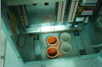
Amendment Register

                     Reference
 Issue / Rev no.                   Description of revision         Authorised by              Date
                      section
                                   Initial release of manual
         1               All                                    Steering committee      July 2013
                                   (2nd edition)
    June 2015            All       Reviewed                     Mana Tavahodi           June 2015
                                   The use of circular pit is
     July 2016            6                                     Robert Hodges           July 2016
                                   preferred to Type 7 pit
                                   Additional requirements
                                   regarding clearance
   March 2021           16.3                                    John Chuong             March 2021
                                   areas around equipment
                                   added

Road Planning and Design Manual – Edition 2: Volume 5, Transport and Main Roads, March 2021          i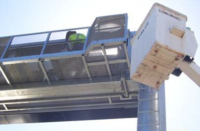
Contents

1     Introduction ....................................................................................................................................1
1.1   Background ..................................................................................................................................... 1
1.2   Early project involvement ................................................................................................................ 2
2     Intelligent Transport Systems design .........................................................................................2
2.1   Intelligent Transport Systems functional design ............................................................................. 2
2.2   Supporting infrastructure ................................................................................................................ 2
2.3   Functional safety ............................................................................................................................. 3
2.4   Main Intelligent Transport Systems ................................................................................................ 3
3     Vehicle Detection Stations ............................................................................................................4
3.1   Introduction ..................................................................................................................................... 4
      3.1.1      In-pavement vehicle detectors .......................................................................................4
      3.1.2      Roadside mounted vehicle detectors .............................................................................5
3.2   Physical components ...................................................................................................................... 6
3.3   Typical layout .................................................................................................................................. 6
3.4   Implementation considerations ....................................................................................................... 7
      3.4.1    Loop installation..............................................................................................................7
      3.4.2    Location and frequency ..................................................................................................7
      3.4.3    Detector type for required application ............................................................................7
      3.4.4    Automatic vehicle location / identification .......................................................................7
      3.4.5    Real estate .....................................................................................................................8
      3.4.6    Rural vehicle detection: minimal intervention .................................................................8
      3.4.7    Urban vehicle detection: future planning ........................................................................8
      3.4.8    Detection on structures ..................................................................................................8
4     Vehicle counters / classifiers .......................................................................................................8
4.1   Introduction ..................................................................................................................................... 8
4.2   Physical components ...................................................................................................................... 9
4.3   Implementation considerations ....................................................................................................... 9
5     Closed Circuit Television systems cameras ...............................................................................9
5.1   Introduction ..................................................................................................................................... 9
5.2   Physical components .................................................................................................................... 11
5.3   Typical layout ................................................................................................................................ 11
5.4   Implementation considerations ..................................................................................................... 12
      5.4.1    Location ....................................................................................................................... 12
      5.4.2    Structural mounting of Closed Circuit Television ........................................................ 12
      5.4.3    Pole type ...................................................................................................................... 12
      5.4.4    Vibration ...................................................................................................................... 13
      5.4.5    Public misconception ................................................................................................... 13
      5.4.6    Communications limitations ......................................................................................... 13
      5.4.7    Closed Circuit Television network security .................................................................. 13
      5.4.8    Closed Circuit Television network design ................................................................... 13
6     Road weather monitoring .......................................................................................................... 14
6.1   Introduction ................................................................................................................................... 14
6.2   Physical components .................................................................................................................... 14

Road Planning and Design Manual – Edition 2: Volume 5, Transport and Main Roads, March 2021                                                       i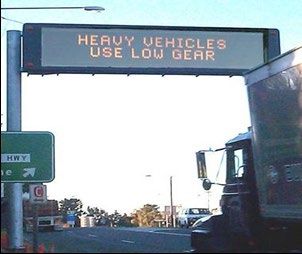
6.3     Typical layout ................................................................................................................................ 14
6.4     Implementation considerations ..................................................................................................... 14
7       Help telephones .......................................................................................................................... 14
7.1     Purpose ......................................................................................................................................... 15
7.2     Physical components .................................................................................................................... 15
7.3     Typical layout ................................................................................................................................ 15
7.4     Implementation considerations ..................................................................................................... 16
        7.4.1    Installation ................................................................................................................... 16
        7.4.2    Frequency .................................................................................................................... 16
        7.4.3    Safety and access ....................................................................................................... 16
        7.4.4    Communications .......................................................................................................... 16
8       Variable Message Signs ............................................................................................................. 17
8.1     Introduction ................................................................................................................................... 17
8.2     Physical components .................................................................................................................... 17
8.3     Typical layout ................................................................................................................................ 18
8.4     Implementation considerations ..................................................................................................... 19
        8.4.1    Size of sign .................................................................................................................. 19
        8.4.2    Sign location ................................................................................................................ 19
        8.4.3    Cabinet, pole and footings ........................................................................................... 19
        8.4.4    Variable Message Signs services ............................................................................... 19
        8.4.5    Public consultation....................................................................................................... 19
9       Changeable Message Signs systems ....................................................................................... 20
9.1     Introduction ................................................................................................................................... 20
9.2     Physical components .................................................................................................................... 20
9.3     Typical layout ................................................................................................................................ 20
9.4     Implementation considerations ..................................................................................................... 22
        9.4.1    Decision time ............................................................................................................... 22
        9.4.2    Sign design .................................................................................................................. 22
        9.4.3    Power supply ............................................................................................................... 22
        9.4.4    Real estate .................................................................................................................. 22
10      Road condition information signs ............................................................................................ 22
10.1 Physical components .................................................................................................................... 23
10.2 Typical layout ................................................................................................................................ 23
10.3 Implementation considerations ..................................................................................................... 23
     10.3.1   Size of sign .................................................................................................................. 23
     10.3.2   Sign location ................................................................................................................ 24
     10.3.3   Number of modules per sign ....................................................................................... 24
     10.3.4   Legal implications ........................................................................................................ 24
     10.3.5   Functional safety ......................................................................................................... 24
11      Variable speed limit / Lane control signs ................................................................................. 24
11.1 Physical components .................................................................................................................... 26
11.2 Typical layout ................................................................................................................................ 26
11.3 Lateral location and height............................................................................................................ 26
11.4 Size ............................................................................................................................................... 27

Road Planning and Design Manual – Edition 2: Volume 5, Transport and Main Roads, March 2021                                                         ii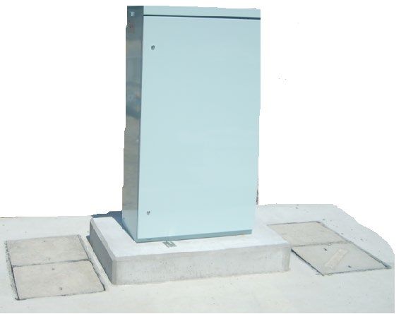
11.5 Cabinet, pole and footings ............................................................................................................ 27
11.6 Variable speed limit / Lane control signs services ........................................................................ 27
11.7 Functional safety ........................................................................................................................... 27
11.8 Operational issues ........................................................................................................................ 27
12 Ramp Metering Systems ............................................................................................................ 27
12.1 Introduction ................................................................................................................................... 27
12.2 Physical components .................................................................................................................... 28
12.2.1 Ramp metering signal lantern and controller .............................................................. 28
12.2.2 Advance warning signage ........................................................................................... 28
12.2.3 Presence detector ....................................................................................................... 28
12.2.4 Passage detector......................................................................................................... 28
12.2.5 Queue detector ............................................................................................................ 28
12.2.6 Mainline detectors ....................................................................................................... 28
12.2.7 Services ....................................................................................................................... 28
12.3 Typical layout ................................................................................................................................ 28
12.4 Implementation considerations ..................................................................................................... 30
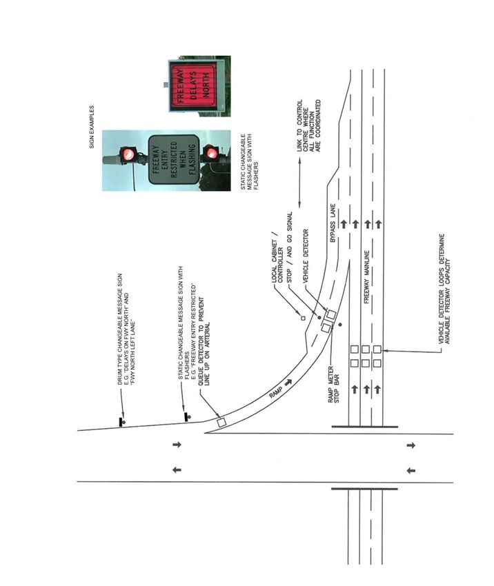
13 Weigh-in-Motion systems .......................................................................................................... 30
13.1 Introduction ................................................................................................................................... 30
13.2 Physical components .................................................................................................................... 30
13.3 Typical layout ................................................................................................................................ 31
13.4 Implementation considerations ..................................................................................................... 31
13.4.1 Installation ................................................................................................................... 31
13.4.2 Positioning ................................................................................................................... 32
14 Automatic number plate recognition systems ........................................................................ 32
14.1 Physical components .................................................................................................................... 32
14.2 Mounting ....................................................................................................................................... 33
14.3 Implementation considerations ..................................................................................................... 33
14.3.1 Accuracy ...................................................................................................................... 33
14.3.2 Number of automatic number plate recognition sites .................................................. 33
14.3.3 Maintenance ................................................................................................................ 34
14.3.4 Automatic number plate recognition services ............................................................. 34
14.3.5 Legal issues ................................................................................................................. 34
15 Tunnel systems ........................................................................................................................... 34
15.1 Introduction ................................................................................................................................... 34
15.2 Physical components .................................................................................................................... 35
15.3 Typical layout ................................................................................................................................ 36
15.4 Implementation considerations ..................................................................................................... 38
15.4.1 Vehicle detector stations ............................................................................................. 38
15.4.2 Help phones ................................................................................................................ 38
15.4.3 Variable Message Signs .............................................................................................. 38
15.4.4 Closed Circuit Television cameras and automatic incident detection ......................... 38
15.4.5 Traffic signals .............................................................................................................. 39
15.4.6 Public address systems and Highway Advisory Radio ............................................... 39
15.4.7 Global Positioning Systems ......................................................................................... 39
15.4.8 Mobile phone re-broadcast system ............................................................................. 39
15.4.9 Radio re-broadcast system ......................................................................................... 39
15.4.10 Over-height detection and warning ............................................................................. 40
Road Planning and Design Manual – Edition 2: Volume 5, Transport and Main Roads, March 2021 iii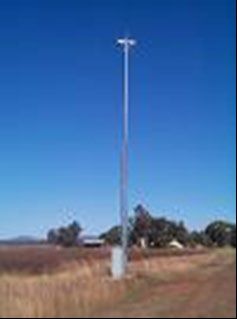
15.4.11         Foreign vehicle detection ............................................................................................ 40
        15.4.12         Tunnel ITS control equipment ..................................................................................... 40
        15.4.13         Ducts, conduits and barriers ........................................................................................ 41
16      Intelligent Transport Systems field equipment ....................................................................... 41
16.1 Real estate .................................................................................................................................... 41
16.2 Intelligent Transport Systems field network .................................................................................. 41
16.3 Cabinets ........................................................................................................................................ 44
16.4 Poles ............................................................................................................................................. 45
     16.4.1        Sign poles .................................................................................................................... 45
     16.4.2        Tilt poles ...................................................................................................................... 45
16.5 Safety and protection of equipment .............................................................................................. 46
     16.5.1    Use of barriers ............................................................................................................. 46
     16.5.2    Protection from vandalism ........................................................................................... 46
16.6 Maintenance access ..................................................................................................................... 46
     16.6.1   Maintenance vehicles .................................................................................................. 46
     16.6.2   Maintenance personnel ............................................................................................... 47
16.7 Restricted corridor ........................................................................................................................ 47
16.8 Pavement design .......................................................................................................................... 48
16.9 Planning issues ............................................................................................................................. 48
17      Emerging Intelligent Transport Systems areas and implications ......................................... 48

Figures

Figure 3.3 - Vehicle Detection Stations layout in a motorway application .............................................. 6

Figure 5.1 - Typical pole-mounted Closed Circuit Television camera at a roadside field site .............. 10

Figure 5.2 - Closed Circuit Television layout in a motorway application ............................................... 11

Figure 7.3 - Help phone layout in a motorway application .................................................................... 16

Figure 8.1 - Variable Message Sign ...................................................................................................... 17

Figure 8.3 - Variable Message Signs layout in a motorway application ................................................ 18

Figure 9.3 - Changeable Message Signs layout in a motorway application ......................................... 21

Figure 10 - Network access sign ........................................................................................................... 23

Figure 11 - Variable speed limit / lane control signs application ........................................................... 25

Figure 11.3 - Variable speed limit / Lane control signs overhead application ....................................... 27

Figure 12.3 - Ramp Metering Systems layout in a motorway application ............................................. 29

Figure 13.3 - Weigh-In-Motion layout in a truck inspection station application ..................................... 31

Figure 14.1 - Pole mounted automatic number plate recognition capture system with wireless
connectivity ............................................................................................................................................ 33

Figure 15.3 - Typical tunnel layout ........................................................................................................ 37

Figure 16.2(a) - Typical civil provisions for a traffic signal post............................................................. 42

Figure 16.2(b) - Cross section through part of roadway ........................................................................ 43

Road Planning and Design Manual – Edition 2: Volume 5, Transport and Main Roads, March 2021                                                        iv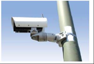
Figure 16.3(a) - Intelligent Transport System field cabinet, showing separate communication and
electrical pits .......................................................................................................................................... 44

Figure 16.3(b) - Proper fit of power and communications conduits in field cabinets............................. 45

Figure 16.6 - Maintenance access at the back of sign .......................................................................... 46

Figure 16.6.1 - Roadside maintenance access ..................................................................................... 47

Tables

Table 8.4.1 - Character size in relation to speed and sighting distance ............................................... 19

Road Planning and Design Manual – Edition 2: Volume 5, Transport and Main Roads, March 2021                                                          v
Volume 5: Intelligent Transport Systems

1      Introduction
This volume covers intelligent transport systems (ITS) with a specific focus on the impact that
ITS deployment has on road civil infrastructure provision. It outlines basic design requirements to be
considered by planners and designers in the delivery of ITS for rural and urban road infrastructure and
tunnels.

Intelligent transport systems are information and communication technologies applied to road
infrastructure and vehicles in order to improve road safety, efficiency as well as reduce impact on the
environment of transportation systems.

    In this version: Additional requirements regarding clearance areas around equipment added to
    Section 16.3.

1.1     Background

There has been a significant increase in transportation demand as a result of economic development,
urbanisation and in particular, the growing trend of ‘just-in-time’ delivery of goods and services. This
demand inevitably results in congested motorways. Traffic congestion contributes to air and noise
pollution, reduces business productivity and competitiveness, and degrades the transportation
network.

The traditional response to traffic congestion has been building more motorways. Yet, construction to
handle increasing traffic loads is becoming more expensive. Financial, environmental, safety, and
other policy and community considerations make expanding the size of the transportation systems
difficult, socially unacceptable and unsustainable. It is increasingly accepted that construction of more
motorways is no longer feasible in many areas as the primary solution to traffic congestion: ‘we cannot
build our way out of congestion’.

Intelligent transport systems (ITS) have proven to be an innovative alternative to traditional measures
for addressing transportation problems and needs.

ITS alone though cannot solve all the transportation problems. Nor can any one technology solve the
growing demand for, and changing patterns of travel. ITS applications do not reduce the demand for
mobility and accessibility nor increase highway capacity. But ITS can provide transportation agencies
with extra levers with which to manage transportation challenges and maximise the safety and
efficiency of existing infrastructure.

ITS application requirements may impact many facets of planning and design including earthworks,
hydraulics, structures, traffic engineering and environmental disciplines and early deployment of ITS
can assist in traffic management during project construction. Therefore, mainstreaming of ITS into the
planning, program and project development processes is critical in order to build and sustain support
for ITS investments.

ITS applications vary from simple traffic control and traveller information systems, to the rapidly
evolving automatic incident detection applications and vehicle-to-infrastructure cooperative systems.

Road Planning and Design Manual – Edition 2: Volume 5, Transport and Main Roads, March 2021           1
Volume 5: Intelligent Transport Systems
1.2 Early project involvement
Early consultation should be made with the Queensland Department of Transport and Main Roads’
Intelligent Transport Systems and Electrical (ITS&E) and Network Operations and
Performance (NO&P) business units for projects where ITS deployments are planned, or likely in
future.
2 Intelligent Transport Systems design
2.1 Intelligent Transport Systems functional design
An ITS functional design needs be undertaken to set the requirements on which the detailed design is
based. The ITS functional design for any new ITS capacity should include:
• the identification of the primary and secondary (if required) Transport and Main Roads
monitoring entities(s); that is, the Brisbane Metropolitan Transport Management
Centre (BMTMC), Busways Operations Centre (BOC), North Coast Hinterland Traffic
Management Centre (NCHD TMC), South Coast Hinterland Traffic Management
Centre (SCHD TMC) or external monitoring party
• integration with the Principal’s existing Transport and Main Roads systems – the contractor
shall confirm the versions of the respective Transport and Main Roads systems that are
applicable to the given project with the departmental Project Representative
• selection of technology which is fit for purpose
• procurement of commercially off-the shelf (COTS) system components; that is, not based on
proprietary standards
• value for money solutions
• product whole-of-life considerations for ongoing administration, maintenance and
management if the ITS is delivered
• security requirements in accordance to Industry and Principal’s specific security
standards / policies
• the design allows for high availability (applicable only for safety critical functions)
• Crime Prevention to Environmental Design (CPTED) principles in the design, and
• equipment which is physically and technologically robust and reliable.
The overall ITS functional design shall be submitted to the departmental Project Representative for
review and approval, at least 14 working days prior to any detailed design being undertaken.
2.2 Supporting infrastructure
It is important that road designers approach provision of ITS supporting infrastructure from a holistic
point of view. This includes consideration of project-related ITS applications which may be outside
immediate project boundaries.
ITS design must take into account road geometry, landscape design, drainage systems, road
structures, other road furniture such as static signs, lighting, services such as electricity and public
utility plant and supplies. Likewise, these services must consider ITS requirements. This will allow
addressing conflicts that may arise regarding ITS equipment space allowances, conduit routes and
Road Planning and Design Manual – Edition 2: Volume 5, Transport and Main Roads, March 2021 2Volume 5: Intelligent Transport Systems
sighting distances with other road services. Site and maintenance access are critical aspects of all
ITS designs.
ITS design must be guided by provisions outlined in this manual, the Manual of Uniform Traffic Control
Devices (Queensland) (MUTCD), Traffic and Road Use Management Manual (TRUM) and relevant
Australian Standards.
The final design may require a compromise in other services so as to accommodate the ITS
necessary to meet traffic management imperatives as mentioned in Volume 1 – Legislation of this
manual.
ITS equipment requires power and reliable communications links to operate efficiently. Civil
infrastructure must allow for the conveyance of ITS electrical and communications cabling. Designs
must allow for ducts, pits, conduits, trays, ladders, antennas, cabinets and wall or structure
penetrations as necessary. Wherever practicable, ITS devices and supporting infrastructure (including
pits and conduits) should be located in the outer verges.
Designers may also need to consider that ITS deployment may be on a temporary and/or ‘early works’
basis to overcome issues during construction. Consideration for possible future road operations
requirements (such as road widening, hard shoulder running and/or separation for differential speed
limits) must be made in the ITS design. While provision of ITS applications may not be required
immediately, land acquisition and civil works should be undertaken to allow these to occur easily in
future.
2.3 Functional safety
Designers must note that it is essential as part of ITS design that preliminary hazard analysis be done
with input from the department’s ITS and Electrical, Network Operations and Performance, and Traffic
Engineering and Data units, and that functional safety requirements are evaluated in accordance with
AS 61508 Functional safety of electrical / electronic / programmable electronic safety-related systems
Set.
2.4 Main Intelligent Transport Systems
The key motivators for providing ITS include:
• improving road safety
• improving road network efficiency
• improving transport system efficiency, and
• reducing environmental impacts of the transport system.
These outcomes demand deployment and integration of a number of systems and subsystems
including:
• road condition or road use data collection systems
• traveller information systems
• traffic management / control systems
• incident management systems
• heavy vehicle management systems, and
• public transport priority / emergency vehicle pre-emption systems.
Road Planning and Design Manual – Edition 2: Volume 5, Transport and Main Roads, March 2021 3Volume 5: Intelligent Transport Systems
These systems depend on many different technologies and devices including: vehicle detectors,
message signs, display monitors, closed circuit television (CCTV) and telecommunications networks.
The specifics of these and other devices and their supporting infrastructure are discussed in the
remainder of this volume.
3 Vehicle Detection Stations
3.1 Introduction
Vehicle Detector Stations (VDS) are a critical element of the road data collection systems and provide
raw vehicular data required by ITS applications. Each detector station may involve a number of
sensors, enabling the collection of basic aggregate measures such as occupancy, volume, and speed.
These sensors may be embedded within the road surface or mounted roadside on poles or structures.
VDS should be placed periodically along a roadway to allow fast detection of congestion and
incidents, and to provide an accurate picture of flow along the entirety of the road.
VDS are also used in ramp metering applications described in more detail later. Ramp Metering
Systems (RMS) optimally use vehicle detection, both on the mainline and on the ramp, to meter
access to congested motorways. Congestion management systems use vehicle detection data to
evaluate and display appropriate messages on Variable Message Signs (VMS) and Variable Speed
Limit Signs (VSLS).
For information relevant to detection in traffic signalling, refer to the Road Planning and Design
Manual (RPDM) (2nd edition) Volume 3 – Guide to Road Design, Part 4 – Intersections and
Crossings – General.
In permanent applications, sensors may be installed within the road surface (in-pavement) or mounted
on the roadside.
3.1.1 In-pavement vehicle detectors
There are various types of sensors that are installed on or embedded in the pavement used for
detecting vehicles. These include:
• piezoelectric sensors
• pneumatic tubes
• magnetic sensors / probes, and
• inductive loops.
Piezoelectric sensors generate a voltage when subjected to a mechanical force. The voltage
developed is proportional to the force applied. This makes such sensors suitable for weigh-in-motion
and vehicle axle based classification applications.
Pneumatic tubes are normally used in temporary installations, due to the ease in installation
requirements. These sensors are installed directly on the road pavement surface. Due to the direct
exposure to vehicle traffic, these sensors have a short lifespan, depending on the types and volumes
of vehicles involved.
Magnetic sensors indicate vehicle presence by detecting disturbance of a magnetic field caused by
the vehicle passing over them. The sensors are suitable for vehicle speed, classification by length and
counting applications. Some sensors transmit vehicular data wirelessly to roadside equipment. Some
of these sensors are beginning to rival inductive loops in terms of application.
Road Planning and Design Manual – Edition 2: Volume 5, Transport and Main Roads, March 2021 4Volume 5: Intelligent Transport Systems
Inductive loops are by far the most commonly used primary means of collecting vehicular data for
ITS applications. They are widely considered both reliable and accurate. Inductive loop sensors are
embedded in the road pavement and are either preformed or cut into the pavement. Preformed loops
are made to order in the factory and installed on site prior to laying pavement. Inductive loops are not
usually compatible with chip-sealed roads. Special considerations are required for concrete
pavements. Further information is provided in the TRUM Volume 4 – ITS and Electrical Technology
Manual, Part 5 – Configuration and Placement of Vehicle Detection Sensors.
3.1.2 Roadside mounted vehicle detectors
Newer alternatives in off-pavement (non-invasive) sensors include:
• video imaging
• Doppler radar
• microwave ranging
• audio and ultrasonic sensing, and
• photoelectric sensors.
Video detection relies on change in contrast of the image being captured to detect vehicle presence or
movement. Video detection is susceptible to harsh weather conditions. Rain and fog, for instance,
affect visibility and hence proper video detection.
Doppler radars use microwave signals to sense vehicles moving towards or away from the radar and
are able to detect vehicle speed. True-presence radar measure distance to a target (range) which may
be moving or stopped and can be used to detect vehicle presence.
Acoustic vehicle sensors may be active or passive. Active acoustic sensors are gantry mounted and
use sound waves they generate onto trafficked lanes in order to determine vehicle presence. They are
used for vehicle counting and classification purposes. Passive sensors detect noise generated by
tyres or winds generated by passing vehicles and are used for traffic flow and speed monitoring.
Evaluations to date have indicated unacceptable performance.
Photoelectric sensors, laser or infrared sensors detect presence or absence of light that the sensors
generate across or above trafficked lanes and are used to detect vehicle presence, over-height
vehicles, speed and in vehicle classification.
The reliability and accuracy of all these sensors depends on the application and environment in which
they are used. Non-invasive sensors provide some advantages in the areas of installation and
maintenance. These activities may be performed without the need for lane closures. These sensors
may also be configured easily for changes in location or detection zones via configuration software.
However, these sensors are also more prone to vandalism and damage due to their high visibility.
They also add to additional furniture on the roadside.
Road Planning and Design Manual – Edition 2: Volume 5, Transport and Main Roads, March 2021 5Volume 5: Intelligent Transport Systems
3.2 Physical components
• Vehicle detecting sensors (usually inductive loop sensors)
• Vehicle detector electronics
• Controller cabinet
• Conduits required for power and communications, and
• Maintenance access.
Often, vehicle detectors are installed as part of a broader ITS application. In these instances, the
sensors may interface to the ITS controller, communications and power.
3.3 Typical layout
The following sketch, Figure 3.3 illustrates a typical VDS installation in a motorway application. Further
information is contained in the TRUM Volume 4, Part 5.
Figure 3.3 - Vehicle Detection Stations layout in a motorway application
Road Planning and Design Manual – Edition 2: Volume 5, Transport and Main Roads, March 2021 6Volume 5: Intelligent Transport Systems
3.4 Implementation considerations
3.4.1 Loop installation
Cut-in loops are installed in the asphalt after paving operation. If open graded asphalt is used, the
loops need to be installed in the dense grade asphalt before the final overlay. Preformed loops require
installation before concreting or paving operation.
• Limitations: Inductive loop tail length, from the field to the cabinet where the detector unit is
housed, must not exceed 200 metres.
• Lane closure: Lane closure is necessary when installing inductive loops or other in-pavement
sensors. Traffic control deployment to facilitate their placement is required.
• Future widening consideration: Future roadway widening should be considered when
positioning detector equipment, sensors, and associated underground infrastructure.
• Placement and line marking: Exact loop coordinates (eastings and northings) need to be
established as part of the design and subsequent line marking. Loops, especially preformed
loops, may be rendered ineffectual, depending on application, if line markings do not take into
account the exact loop positions.
• Reinforcing steel: Concrete pavement reinforcement can affect operation of detector loops.
The minimum distance between the loop and reinforcement that allows proper loop operation
needs to be verified with the loop manufacturer.
• Pavement type can also affect the operating performance, installation and maintenance of
loops, for example, asphalt, concrete, chipseal.
3.4.2 Location and frequency
Vehicle detector stations shall be located at each motorway interchange to allow detection of both
mainline and on / off ramp traffic. At an interchange, the VDS may be integrated into a ramp metering
system (RMS), or some other ITS application. Preferably, detection devices should be located in
situations that have minimal vehicle weaving movements. Shorter separation should be used for
bridges and tunnels.
In a motorway application, VDS placement is dictated by the needs of the system. Further details are
provided in TRUM Volume 4, Part 5 and the managed motorways ITS placement guidelines (pending
publication – contact the department’s Network Operations and Performance unit).
3.4.3 Detector type for required application
The detection technology should be suitable for the required application. Technology adopted must
best offer accuracy and reliability under the road conditions expected.
3.4.4 Automatic vehicle location / identification
In-pavement sensors may be used in conjunction with vehicles that have specially fitted transmitters in
order to derive location of the vehicle. This may be for the purposes of real-time passenger information
system or public transport priority scheme implementation. These detectors should be placed
strategically at entrances, exit points and other points along the route of the target traffic. On-board
computers with GPS, as well as GSM / GPRS / 3G connectivity, sometimes called transport personal
computers, are increasingly being used for this purpose. In future, this technology may reduce or
eliminate the need for in-pavement sensors for these applications.
Road Planning and Design Manual – Edition 2: Volume 5, Transport and Main Roads, March 2021 7Volume 5: Intelligent Transport Systems 3.4.5 Real estate Field cabinets must be installed to allow easy and safe access for maintenance and should ideally be located on the outside verge. Direct access to power and communications links should also be considered. Limitations exist in positioning field cabinets away from the sensors. When long structures are involved, special consideration must be given to accommodate installing field cabinets on the structures. Refer also to Section 16. 3.4.6 Rural vehicle detection: minimal intervention A rural vehicle detection station design should require minimal maintenance and user intervention. Pavement depth should be verified if in-pavement sensor technologies are under consideration in low depth seals. 3.4.7 Urban vehicle detection: future planning Strategic planning of VDS designs in urban areas may prove most useful when provisioning for future expansion. This includes both the detection devices and the real estate required for these devices. The roadways design should include real estate for poles, cabinets and other roadside furniture, in order to reduce future expansion / relocation costs. 3.4.8 Detection on structures Sensors or detectors shall in no way violate the structural integrity of the members or road furniture on which they are mounted. In-pavement sensing may not be possible at a bridge and roadside detection needs to be considered. Stick-on detector loops may only be used for temporary applications (typically up to one week total duration). Detectors may be placed on bridge approaches to help minimise the restrictions that apply at bridge structures. Maintenance access shall be considered in the final location of devices. Any existing pole or structure used for the mounting of sensors or detectors shall be inspected by a structural Registered Professional Engineer of Queensland (RPEQ). Any design using an existing pole or structure shall ensure the combined sensors or detector installation configuration is certified by a structural RPEQ for such characteristics including structural wind and mechanical loadings. 4 Vehicle counters / classifiers 4.1 Introduction Vehicle counters / classifiers collect and record traffic volume and vehicle classification data. Classification may even be an additional feature of the vehicle detection systems described previously. Classification may be done on the basis of speed, vehicle length and/or number of axles. Austroads 12-bin classification bases classification on the number of axles and distance between axles or axle groups and has been widely adopted. The system accommodates vehicles and vehicle combinations with up to sixteen axles. Data capture may include lane of travel of each vehicle, accumulated counts by lane, date, time of day and classification. Four-bin classification is based on vehicle length. Road agencies in Australia and New Zealand are moving towards harmonising vehicle lengths for the various bins. Road Planning and Design Manual – Edition 2: Volume 5, Transport and Main Roads, March 2021 8
Volume 5: Intelligent Transport Systems

Vehicle counters / classifiers may rely on pneumatic tubes, detector loops, piezos, laser, infrared or
radar technology. The latter three are non-intrusive and do not require sensors in the pavement.
Pneumatic tubes are normally used for temporary applications.

4.2       Physical components

Vehicle counters / classifiers components may include:

      •    a data logging device capable of collecting, processing, storing and transmitting vehicular data

      •    axle sensors to detect vehicles, vehicle speed, axle counts and axle spacings – the sensors
           may be pneumatic tubes, loops, or piezoelectric sensors

      •    communications interface to allow local / remote connectivity

      •    field cabinet and all necessary interconnecting cables and miscellaneous materials to make an
           operational system, and/or

      •    maintenance access.

4.3       Implementation considerations

Where classifiers are not installed on existing roads, they should be provided during the planning
phase of respective road projects. This will enable effective data collection which will further inform
project decisions.

A conduit system should be designed for the connection of power and telecommunications to vehicle
count / classifier site.

For motorways, classifiers should be placed on both carriageways midway between all interchanges.

Off-pavement classifiers such as the infrared based units may suffer from occlusion during periods of
heavy traffic and accuracy may degrade as a result. Roadside equipment may need realignment
periodically since it is less immune to vibrations.

5     Closed Circuit Television systems cameras
5.1       Introduction

Closed Circuit Television (CCTV) systems provide a means by which road agencies may effectively
monitor the road network, detect and respond to incidents. Figure 5.1 shows a camera arrangement
typically adopted for roadside CCTV coverage. The main components in the field site on a roadway
include an ITS field cabinet, camera pole and base and the camera and mount.

Real-time CCTV coverage allows Traffic Management Centre operational staff to immediately identify
incidents as they occur as the time with which an incident is detected / verified affects the time with
which it is responded to and effectively managed to minimise the amount of disruption to the traffic
flows as a result.

Refer to MRTS225 Imaging specification for details on the design, supply, installation, testing and
commissioning, performance, documentation, training and maintenance requirements of imaging
infrastructure / services for ITS network applications.

Road Planning and Design Manual – Edition 2: Volume 5, Transport and Main Roads, March 2021           9
Volume 5: Intelligent Transport Systems
Figure 5.1 - Typical pole-mounted Closed Circuit Television camera at a roadside field site
Typical incident verification includes:
• confirming that an incident has occurred
• determining the exact location and direction of travel, and
• obtaining and assessing the nature and as many additional details about the incident as
possible.
Operators are able to verify the incident, carry out an initial assessment of the incident severity and
estimate the resources needed to respond to the incident (for example, emergency vehicles).
CCTV technologies are increasingly being used for automatic incident detection (AID), especially in
tunnel environments. The video image processing system can prompt the traffic management centre
operator via tunnel operational management systems, should an incident be detected. AID may
address incidents such as smoke presence, stationary vehicle, unauthorised pedestrian crossings,
fallen debris, any vehicle travelling in the wrong direction, tailgating or sudden speed changes in the
monitored zone. AID reduces reliance on traffic management operators for incident detection. This is
important to promote reliable and fast incident detection.
IP cameras have found use in applications such as posting of motorway traffic video images on the
internet as part of a traveller information service. In this application, cameras give travellers the
privilege of viewing road network conditions at points of interest before embarking on their journeys.
Bandwidth considerations and privacy issues may require that such images be of low resolution.
Webcams may also be used to verify images displayed by electronic road condition signs, or at sites
with low bandwidth and/or slowly / infrequently changing images.
Video images can also be used to assist in maintenance operations.
CCTV capability within tunnels is typically integrated into the local plant, control and management
systems to provide greater situational awareness to the operators. For example, the fire, life and
safety system may be integrated with the CCTV system, such that operators are provided with a visual
Road Planning and Design Manual – Edition 2: Volume 5, Transport and Main Roads, March 2021 10Volume 5: Intelligent Transport Systems
alarm when a critical system, such as the deluge or egress pressurisation system, has been alarmed
or activated.
5.2 Physical components
The equipment required to implement a closed circuit television or web camera subsystem includes:
• cameras mounted on existing structures such as overpasses, fixed and swing poles, or the
rooftops adjacent to the corridor to be monitored – ideally, the cameras should be capable of
vertical and rotational movement with zoom capabilities (pan, tilt zoom, or PTZ which is not a
requirement in most web camera applications)
• controller cabinet
• conduits for power and communications
• maintenance access, and
• lightning protection.
5.3 Typical layout
Usually, CCTV cameras are mounted on a pole or a fixed structure. If a tilt pole is used, an area on
the outer verge is needed to tilt the pole safely without affecting traffic. Refer also to Section 16.
A typical layout for CCTV in a motorway application is shown in Figure 5.3.
Figure 5.2 - Closed Circuit Television layout in a motorway application
Road Planning and Design Manual – Edition 2: Volume 5, Transport and Main Roads, March 2021 11You can also read