ROOF TRUSS TABLES - MITEK
←
→
Page content transcription
If your browser does not render page correctly, please read the page content below
Equipment Manual

                    Roof Truss Tables

Copyright © 2018, 2020 MiTek®. All rights reserved.                                      001090 rev. C
Patented. See Legal Notice for list of patents.
Manual applies to United States equipment.

                MiTek recommends printing this manual in high resolution using color ink. Many of the
CAUTION         graphics may be unclear and may create an unsafe condition if this recommendation is not
                followed.
Equipment Manual

                Roof Truss Tables

MiTek Machinery Division              Part # and Rev.    001090 rev. C
301 Fountain Lakes Industrial Drive   Print Date         21 May 2021
St. Charles, MO 63301                 Effectivity        31580-xxx
                                                         31595-xxx
Phone: 800-523-3380                                      31610-xxx
Fax: 636-328-9218                     Revision Date      21 May 2021
www.mitek-us.com                      Revised By         A. McIntire
                                      Orig. Release Date 1 April 2007
                                      Created By         R. Widder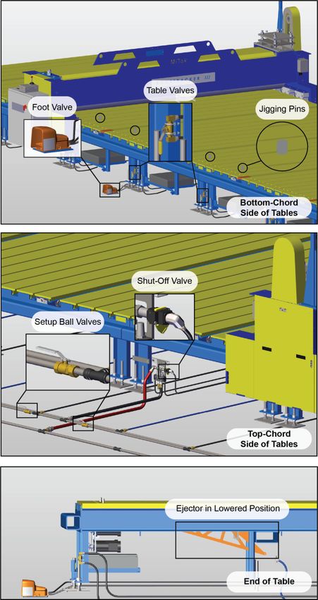
Legal Notice
Patents
Made and sold under one or more of the following patents:
U.S. 4,986,052                U.S. 5,837,014                U.S. 6,219,975
U.S. 5,385,339                U.S. 5,854,747                U.S. 6,260,263
U.S. 5,493,834                U.S. 5,873,567                U.S. 6,317,980
U.S. 5,568,862,               U.S. 5,884,448                U.S. 6,389,762
U.S. 5,630,697                U.S. 5,885,731                U.S. 6,401,422
U.S. 5,636,494                U.S. 5,906,264                U.S. 6,412,246
U.S. 5,638,658                U.S. 5,934,866                U.S. 6,418,601
U.S. 5,640,832                U.S. 5,947,460                U.S. 6,539,615
U.S. 5,655,399                U.S. 5,987,828                U.S. 6,666,367
U.S. 5,678,395                U.S. 5,996,303                U.S. 6,702,269
U.S. 5,702,095                U.S. 6,048,165                U.S. 6,758,022
U.S. 5,707,204                U.S. 6,112,968                U.S. 6,817,392
U.S. 5,735,087                U.S. 6,134,775                U.S. 6,834,470
U.S. 5,810,341                U.S. 6,170,688                U.S. 6,907,820
U.S. 5,819,412                U.S. 6,205,637                Other patents may apply
U.S. 5,833,222                U.S. 6,212,849

Return Goods Policy
Return goods cannot be accepted without prior authorization and are subject to a
restocking charge. The Seller certifies the articles specified herein were produced in
compliance with all provisions of the Fair Labor Standards Act of 1938, as amended,
including Section 12.—Rev. 6/98.

Corrections and Improvements
To report errors or recommend improvements to this manual, please complete the
Document Evaluation Form in the appendices. Mail or fax the form to:
MiTek Machinery Division
301 Fountain Lakes Industrial Drive
St. Charles, MO 63301
Attn: Engineering Manager, Fax: 636-328-9218

Original Instructions: 001090 rev. C                                                     ii
Notice of Change
Roof Gantry Tables
Use this page to record service bulletins and notices that you receive to keep your manual
updated.

Number           Date       Title

Original Instructions: 001090 rev. C                                                    iii
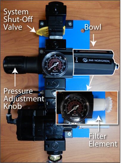
Table of Contents

Legal Notice                                                                                                                       ii
    Patents . . . . . . . . . . . . . . . . . . . . . . . . . . . . . . . . . . . . . . . . . . . . . . . . . . . . . . . . . . . ii
    Return Goods Policy . . . . . . . . . . . . . . . . . . . . . . . . . . . . . . . . . . . . . . . . . . . . . . . . ii
    Corrections and Improvements . . . . . . . . . . . . . . . . . . . . . . . . . . . . . . . . . . . . . . . ii
Notice of Change                                                                                                                  iii
Safety (English)                                                                                                               vii
    Safety Indicator Signal Words . . . . . . . . . . . . . . . . . . . . . . . . . . . . . . . . . . . . . . . vii
    Safety Requirements . . . . . . . . . . . . . . . . . . . . . . . . . . . . . . . . . . . . . . . . . . . . . . . viii
       General Equipment Safety Rules . . . . . . . . . . . . . . . . . . . . . . . . . . . . . . . . . . . viii
       Lockout/Tagout . . . . . . . . . . . . . . . . . . . . . . . . . . . . . . . . . . . . . . . . . . . . . . . . . . xi
       Troubleshooting with an Energized Machine. . . . . . . . . . . . . . . . . . . . . . . . . . . xiv
    Safety Tests . . . . . . . . . . . . . . . . . . . . . . . . . . . . . . . . . . . . . . . . . . . . . . . . . . . . . . xv
    Restricted Zone . . . . . . . . . . . . . . . . . . . . . . . . . . . . . . . . . . . . . . . . . . . . . . . . . . . xvi
    Safety Symbol Definitions. . . . . . . . . . . . . . . . . . . . . . . . . . . . . . . . . . . . . . . . . . xvii
    Declaration of Safety Conformity . . . . . . . . . . . . . . . . . . . . . . . . . . . . . . . . . . . . . xxi
Seguridad (Español)                                                                                                          xxii
    Indicadores de seguridad: Palabras de aviso . . . . . . . . . . . . . . . . . . . . . . . . . . xxii
    Requerimientos de seguridad. . . . . . . . . . . . . . . . . . . . . . . . . . . . . . . . . . . . . . . xxiii
        Reglas general de seguridad para el equipo . . . . . . . . . . . . . . . . . . . . . . . . . . xxiii
        Bloqueo/Etiquetado . . . . . . . . . . . . . . . . . . . . . . . . . . . . . . . . . . . . . . . . . . . . . xxvii
        Solución de problemas con una máquina energizada. . . . . . . . . . . . . . . . . . . xxx
    Prueba de seguridad . . . . . . . . . . . . . . . . . . . . . . . . . . . . . . . . . . . . . . . . . . . . . . xxxi
    Zona Restringida . . . . . . . . . . . . . . . . . . . . . . . . . . . . . . . . . . . . . . . . . . . . . . . . xxxii
    Información adicional . . . . . . . . . . . . . . . . . . . . . . . . . . . . . . . . . . . . . . . . . . . . xxxii
Introduction                                                                                                                       1
    Introduction to the Manual . . . . . . . . . . . . . . . . . . . . . . . . . . . . . . . . . . . . . . . . . . .               1
        Purpose of This Manual. . . . . . . . . . . . . . . . . . . . . . . . . . . . . . . . . . . . . . . . . . . .              1
        Scope of This Manual . . . . . . . . . . . . . . . . . . . . . . . . . . . . . . . . . . . . . . . . . . . . .             2
        The Drawing Set . . . . . . . . . . . . . . . . . . . . . . . . . . . . . . . . . . . . . . . . . . . . . . . . .          2
    Additional Resources . . . . . . . . . . . . . . . . . . . . . . . . . . . . . . . . . . . . . . . . . . . . . . .             4
        Website . . . . . . . . . . . . . . . . . . . . . . . . . . . . . . . . . . . . . . . . . . . . . . . . . . . . . . . .    4
        Phone or E-mail Support . . . . . . . . . . . . . . . . . . . . . . . . . . . . . . . . . . . . . . . . . . .              4
        Contact Information . . . . . . . . . . . . . . . . . . . . . . . . . . . . . . . . . . . . . . . . . . . . . . .          4
General Information                                                                                                                5
    Introduction to the Equipment . . . . . . . . . . . . . . . . . . . . . . . . . . . . . . . . . . . . . . . .                  5
        Purpose of the Equipment . . . . . . . . . . . . . . . . . . . . . . . . . . . . . . . . . . . . . . . . . .               5
        Description of the Equipment . . . . . . . . . . . . . . . . . . . . . . . . . . . . . . . . . . . . . . .                 5
        Safety Compliance of the Equipment . . . . . . . . . . . . . . . . . . . . . . . . . . . . . . . . .                       5
    Components Overview . . . . . . . . . . . . . . . . . . . . . . . . . . . . . . . . . . . . . . . . . . . . . .                7
    Technical Specifications . . . . . . . . . . . . . . . . . . . . . . . . . . . . . . . . . . . . . . . . . . . . .             7
Installation                                                                                                                       8
    Installation Requirements . . . . . . . . . . . . . . . . . . . . . . . . . . . . . . . . . . . . . . . . . . . . 8
        Environmental Requirements . . . . . . . . . . . . . . . . . . . . . . . . . . . . . . . . . . . . . . . 8
        Infrastructure Requirements . . . . . . . . . . . . . . . . . . . . . . . . . . . . . . . . . . . . . . . . 8

Original Instructions: 001090 rev. C                                                                                              iv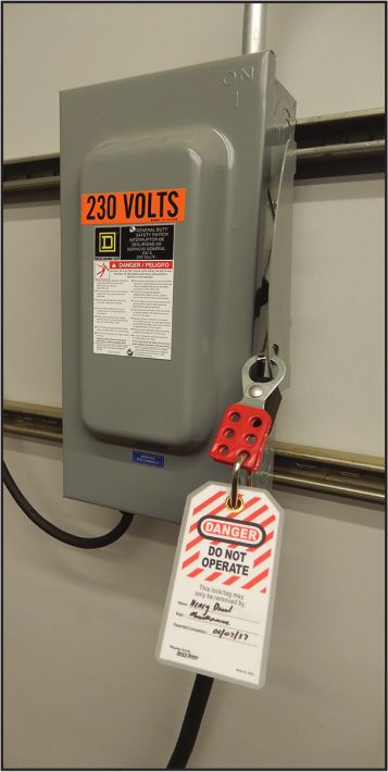
Table of Contents

    Responsibilities During Installation . . . . . . . . . . . . . . . . . . . . . . . . . . . . . . . . . . .                 10
    Responsibilities Before Moving or Selling . . . . . . . . . . . . . . . . . . . . . . . . . . . . .                        10
    Marking Restricted Zone . . . . . . . . . . . . . . . . . . . . . . . . . . . . . . . . . . . . . . . . . . . .            10
       Marking Area on Your Own . . . . . . . . . . . . . . . . . . . . . . . . . . . . . . . . . . . . . . . .                10
       Installing MiTek Restricted Zone Tape . . . . . . . . . . . . . . . . . . . . . . . . . . . . . . .                     10
    Local Codes and Regulations. . . . . . . . . . . . . . . . . . . . . . . . . . . . . . . . . . . . . . . .                 11
Operation                                                                                                                      12
    Before You Begin . . . . . . . . . . . . . . . . . . . . . . . . . . . . . . . . . . . . . . . . . . . . . . . . . .       12
    Operator Controls . . . . . . . . . . . . . . . . . . . . . . . . . . . . . . . . . . . . . . . . . . . . . . . . .        13
       Stopping the Machine . . . . . . . . . . . . . . . . . . . . . . . . . . . . . . . . . . . . . . . . . . . .            13
       Understanding the Table Components . . . . . . . . . . . . . . . . . . . . . . . . . . . . . . .                        13
       Control Valves . . . . . . . . . . . . . . . . . . . . . . . . . . . . . . . . . . . . . . . . . . . . . . . . . .      13
    Operating Procedure . . . . . . . . . . . . . . . . . . . . . . . . . . . . . . . . . . . . . . . . . . . . . . .          15
       Operating the Tables . . . . . . . . . . . . . . . . . . . . . . . . . . . . . . . . . . . . . . . . . . . . .          15
       Operating the Pneumatic Ejection System . . . . . . . . . . . . . . . . . . . . . . . . . . . .                         15
Maintenance                                                                                                                    17
    Performing Maintenance Safely . . . . . . . . . . . . . . . . . . . . . . . . . . . . . . . . . . . . . .                  17
        Before Operating This Machine . . . . . . . . . . . . . . . . . . . . . . . . . . . . . . . . . . . . .                17
        Lockout/Tagout . . . . . . . . . . . . . . . . . . . . . . . . . . . . . . . . . . . . . . . . . . . . . . . . .       18
        Important Safety Information . . . . . . . . . . . . . . . . . . . . . . . . . . . . . . . . . . . . . . .             18
        Making Adjustments and Replacing Parts . . . . . . . . . . . . . . . . . . . . . . . . . . . . .                       20
        Wearing Personal Protective Equipment . . . . . . . . . . . . . . . . . . . . . . . . . . . . . .                      21
        Testing the Safety of the Machine . . . . . . . . . . . . . . . . . . . . . . . . . . . . . . . . . . .                21
    Cleaning and Inspecting . . . . . . . . . . . . . . . . . . . . . . . . . . . . . . . . . . . . . . . . . . . .            21
        Cleaning . . . . . . . . . . . . . . . . . . . . . . . . . . . . . . . . . . . . . . . . . . . . . . . . . . . . . .   21
        Inspecting the Ejectors . . . . . . . . . . . . . . . . . . . . . . . . . . . . . . . . . . . . . . . . . . .          22
        Inspecting the Ejection System as a Whole . . . . . . . . . . . . . . . . . . . . . . . . . . .                        22
    Pneumatic System Maintenance . . . . . . . . . . . . . . . . . . . . . . . . . . . . . . . . . . . . .                     22
        Removing Pressure from the Pneumatic System . . . . . . . . . . . . . . . . . . . . . . .                              22
        Filter/Regulator . . . . . . . . . . . . . . . . . . . . . . . . . . . . . . . . . . . . . . . . . . . . . . . . .     23
        Setup Valve . . . . . . . . . . . . . . . . . . . . . . . . . . . . . . . . . . . . . . . . . . . . . . . . . . . .    24
        Control Valves . . . . . . . . . . . . . . . . . . . . . . . . . . . . . . . . . . . . . . . . . . . . . . . . . .     25
        Ejector Cylinders . . . . . . . . . . . . . . . . . . . . . . . . . . . . . . . . . . . . . . . . . . . . . . . .      26
        High Slope Ejector Bumpers . . . . . . . . . . . . . . . . . . . . . . . . . . . . . . . . . . . . . . .               27
Troubleshooting                                                                                                                29
    Safety Notes for Troubleshooting . . . . . . . . . . . . . . . . . . . . . . . . . . . . . . . . . . . .                   29
       General Troubleshooting Safety Tips . . . . . . . . . . . . . . . . . . . . . . . . . . . . . . . .                     29
       Electrical Troubleshooting Safety Tips . . . . . . . . . . . . . . . . . . . . . . . . . . . . . . .                    30
    Getting Started with Troubleshooting . . . . . . . . . . . . . . . . . . . . . . . . . . . . . . . . .                     31
       Tools Required . . . . . . . . . . . . . . . . . . . . . . . . . . . . . . . . . . . . . . . . . . . . . . . . .        31
       First Steps . . . . . . . . . . . . . . . . . . . . . . . . . . . . . . . . . . . . . . . . . . . . . . . . . . . . .   32
    Problems and Solutions . . . . . . . . . . . . . . . . . . . . . . . . . . . . . . . . . . . . . . . . . . . .             33
Parts List                                                                                                                     34
    Ordering Parts . . . . . . . . . . . . . . . . . . . . . . . . . . . . . . . . . . . . . . . . . . . . . . . . . . . .     34
    Stocking Spare Parts . . . . . . . . . . . . . . . . . . . . . . . . . . . . . . . . . . . . . . . . . . . . . . .         34
    Safety Notes for Replacement Parts . . . . . . . . . . . . . . . . . . . . . . . . . . . . . . . . . .                     34
       List of Parts to Keep in Stock . . . . . . . . . . . . . . . . . . . . . . . . . . . . . . . . . . . . . .              35
Maintenance Checklist                                                                                                          36
    Using the Maintenance Checklists . . . . . . . . . . . . . . . . . . . . . . . . . . . . . . . . . . . . 36
    Safety Notes for the Maintenance Checklists . . . . . . . . . . . . . . . . . . . . . . . . . . . 36
    Checklist . . . . . . . . . . . . . . . . . . . . . . . . . . . . . . . . . . . . . . . . . . . . . . . . . . . . . . . . . 37

Original Instructions: 001090 rev. C                                                                                            v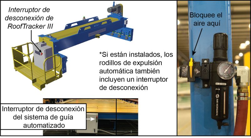
Table of Contents

Drawing Set                                                                                                          38
Document Evaluation                                                                                                  39
    Document Evaluation Form . . . . . . . . . . . . . . . . . . . . . . . . . . . . . . . . . . . . . . . . . 40
       General Evaluation . . . . . . . . . . . . . . . . . . . . . . . . . . . . . . . . . . . . . . . . . . . . . . 40
       Specific Evaluation . . . . . . . . . . . . . . . . . . . . . . . . . . . . . . . . . . . . . . . . . . . . . . 40
Glossary                                                                                                             41
Index                                                                                                                45

Original Instructions: 001090 rev. C                                                                                  vi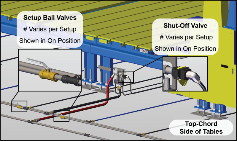
Safety (English)
   Purpose       This chapter explains general information and specific procedures for operating
  of Chapter     the machine safety.

Safety Indicator Signal Words
The following signal words and colors are used throughout this document to indicate
safety hazards. Pay careful attention when you see them. The level of severity differs for
each signal word and color.
Signal words are accompanied by graphics showing what personnel should or should not
do. The graphics are called safety symbols and are defined on page xvii, but more specific
                                                                                                    Refiérase a la
text is provided every time a graphic is used throughout the manual. Everyone near the
                                                                                                    pagina xxii para
machine must be trained on how to read these safety indicators.
                                                                                                    español.
Failure to comply with the instructions accompanying each signal word may result in
                                                                                                    For safety
property damage, personal injury, or even death. Personnel must follow all safety
                                                                                                    information in
procedures and practices to ensure the safest possible operation of this equipment.
                                                                                                    Spanish, refer to
However, at no time is this document a substitute for common sense. Personnel must
                                                                                                    page xxii
ensure that the work environment is safe and free of distractions.
    danger
    Indicates an imminently hazardous situation which, if not avoided, is likely to
    result in death or serious injury.
    warning
    Indicates a potentially hazardous situation, which, if not avoided, may result in
    death or serious injury.
    caution
    Indicates a potentially hazardous situation which, if not avoided, may result in
    minor or moderate injury.
    notice
    Calls attention to information that is significant to understanding the operation at
    hand or the potential for property damage.
    environmental
    Applies to conditions that may affect the environment but do not have an
    immediate, direct effect on personnel or equipment.

Original Instructions: 001090 rev. C                                                          vii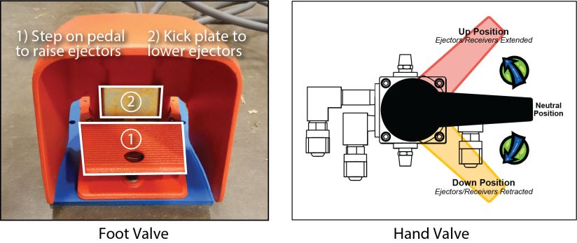
Safety

Safety Requirements
Because it is impossible to anticipate every circumstance that might involve a hazard, the
safety information provided in this equipment manual and on the machine is not all-
inclusive. If this machine is operated or serviced using a procedure not specifically
recommended by the manufacturer, the procedure shall be approved by a professional
engineer to ensure it will not render the equipment unsafe. Use extreme caution and
common sense at all times.

General Equipment Safety Rules
Know Your Equipment

    •   Read this manual completely before using or maintaining the equipment. Do not
        operate this machine unless you have a thorough knowledge of the controls, safety
        devices, emergency stops, and operating procedures outlined in this manual.
    •   Read and follow all safety notes. Failure to comply with these instructions may
        result in economic loss, property damage, and/or personal injury including death.
    •   Refer to the lockout/tagout guidelines on the following pages to safely perform
        maintenance and troubleshooting of this equipment.
    •   Observe and obey all safety labels. Replace worn labels immediately.
    •   Use this equipment solely for the purpose described in this manual.
    •   MiTek equipment is designed to work with optional accessories and other MiTek
        machines. When applicable, refer to the appropriate equipment manual for
        specific safety information.
    •   Only qualified personnel should attempt to operate or perform maintenance on
        this equipment. “Qualified personnel” is defined as:
        ...a person or persons who, by possession of a recognized degree or certificate of
        professional training, or who, by extensive knowledge, training, or experience,
        has successfully demonstrated the ability to solve problems relating to the subject
        matter and work—ANSI B30.2-1983
        ...one who has skills and knowledge related to the construction and operation of
        the electrical equipment and installations and has received safety training on the
        hazards involved—NEC 2002 Handbook

Personal Safety

    •   Always wear safety glasses and hearing protection in an industrial environment.
    •   Utilize a filtering face piece (dust mask) when working near sawdust.
    •   Wear proper clothing and appropriate personal protective equipment (e.g., safety
        glasses and hearing protection.) Do not wear loose clothing or jewelry. Confine
        long hair by tying it back.
    •   Use caution when lifting heavy parts or material.
    •   Pay attention to your surroundings.

Original Instructions: 001090 rev. C                                                   viii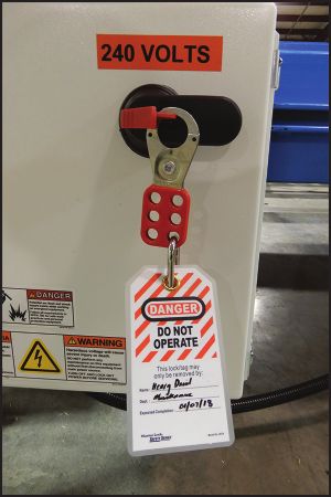
Safety

Installing the Equipment

    •   Follow installation instructions completely.
    •   This equipment is not for use in a residential area.

Lockout/Tagout

    •   Before performing maintenance on the pneumatic or hydraulic systems, bleed the
        lines to eliminate pressure. Refer to Removing Pressure from the Pneumatic
        System.
    •   Lockout/tagout all energized systems before performing maintenance on them.
        Refer to lockout/tagout guidelines in on page xi.

Keeping a Safe Environment

    •   Keep children away. All visitors should be kept a safe distance from the work
        area. Hazards may not be apparent to individuals unfamiliar with the machine.
    •   Keep work areas well lit.
    •   Keep the work area clean and free of any trip or slip hazards.
    •   Do not use the equipment in damp or wet locations, or expose it to rain or snow.
    •   Minimize dust clouds and protect your equipment by cleaning dust in this manner:
        a) Vacuum dust prior to blowing with air
        b) Shut down electrical power and sources of ignition
        c) If using compressed air, it should be a low compression (no more than 15 psi)
        d) Powered cleaning equipment such as vacuums must be consistent with local
           governmental codes for use in dusty conditions.

Operating and Maintaining the Equipment

    •   Ensure that all people, tools, and foreign objects are clear of the restricted zones
        before operating this equipment. The restricted zones are shown on page xvi.
    •   Perform safety tests to ensure all E-stops are working properly before operating
        the equipment at the initial startup, after performing any maintenance, and in
        accordance with the maintenance schedule.
    •   In case of machine malfunction, stop the machine immediately using an E-stop
        and report the malfunction to a supervisor.
    •   Never leave the machine running unattended. Turn the power off! Do not leave
        the machine until all parts have come to a complete stop and all electrical power
        has been shut off.
    •   Check for worn or damaged parts regularly. Repair or replace them immediately.
    •   Keep the hydraulic, pneumatic, and electrical systems in good working order at all
        times. Repair leaks and loose connections immediately. Never exceed the
        recommended pressure or electrical power.

Original Instructions: 001090 rev. C                                                       ix
Safety
• Check that all safety devices are in working order before each shift starts. All
protective guards and safety devices must be in place before and during use of the
machine. Never disconnect or bypass any safety device or electrical interlock.
• Only qualified maintenance personnel shall remove or install safety devices.
• Periodically inspect the quality of the finished product.
Electrical Safety
• Do not use any liquids in the interior of electrical cabinets.
• When using solvents on and around the machine, remove power to the machine to
eliminate the chance of sparking, resulting in explosion or fire. Wear a respirator
approved for use with solvents. Wear protective clothing, gloves, and safety
glasses.
Original Instructions: 001090 rev. C xSafety
Lockout/Tagout
Lockout/Tagout Guidelines
All lockout/tagout guidelines must be met according Figure 1-1: An Example of a
to OSHA 29 CFR 1910.147. A specific procedure Lockout/Tagout Device
should be included in your company’s energy control
program. This manual is not intended to replace your
company’s de-energizing or lockout/tagout procedure
required by OSHA, but merely to provide general
guidance.
The term “lockout,” as used in this manual, means
placing a lockout device on any and all energy sources to
ensure that the energy isolating device and the equipment
being controlled cannot be re-energized or operated until
the lockout device is removed. Figure 1-2shows where
the electrical disconnects are located for this machine.
• Energy sources include electrical, mechanical,
hydraulic, pneumatic, chemical, thermal, or
other energy.
• In the case of electrical energy sources, the main
power and control power to the machinery must
be turned off and physically locked in the Off position.
• A lockout device is usually a keyed padlock.
If more than one person is working in a restricted zone, use a group lockout device that
will allow each person to use a lock that can be removed only by the person performing
the maintenance.
“Tagout” means that a prominent warning is securely fastened to an energy-isolating
device to indicate that the equipment shall not be operated.
Whenever you see this symbol, lockout/tagout!
Original Instructions: 001090 rev. C xiSafety
Electrical Lockout/Tagout Procedures: Outside Machine’s Enclosure
If you are working inside the machine’s enclosure, follow the
procedure on page xiii.
Before performing maintenance on any machine with electrical power, lockout/tagout the
machine properly. When working on a machine outside of the machine’s main electrical
enclosure, not including work on the electrical transmission line to the machine, follow
your company’s approved lockout/tagout procedures which should include, but are not
limited to the steps here.
1. Engage an E-stop on the machine.
2. Turn the disconnect switch handle to the Off position. See Figure 1-2.
! WARNING
ELECTROCUTION HAZARD.
When the disconnect switch is off, there is still live power within
the disconnect switch’s enclosure. Always turn off the power at
the building’s power source to the equipment before opening this
electrical enclosure.
3. Attach a lock and tag that meet OSHA requirements for lockout/tagout.
4. Restrain or de-energize all pneumatic components, hydraulic components, and
other parts that could have live or stored power.
Figure 1-2: Disconnect Switches to Lockout /Tagout for Various Maintenance
Original Instructions: 001090 rev. C xiiSafety
Electrical Lockout/Tagout Procedures:
Inside Machine’s Enclosure
If you are working on the electrical transmission line to the
machine, follow the procedure on page xii.
Before opening the main electrical enclosure, or attempting to repair or replace an
electrical transmission line to the machine, lockout/tagout the machine properly. Follow
your company’s approved lockout/tagout procedures which should include, but are not
limited to the steps here.
1. Engage an E-stop on the Figure 1-3: Sample of a Lockout/
machine. Tagout Mechanism on a Power
Source Panel
2. Shut the power to the machine
off at the machine’s power
source which is usually an
electrical service entry panel
on the facility wall. One
example of a locked-out power
source panel is shown in
Figure 1-3.
3. Attach a lock and tag that
meets OSHA requirements for
lockout/tagout.
4. Open the door to the enclosure
in which you need access, and
using a multimeter, verify that
the power is off.
Original Instructions: 001090 rev. C xiiiSafety Pneumatic System Lockout/Tagout Procedure: WITH Lockout/Tagout If working on components other than the pneumatic system, but that requires you to be near the vicinity of movable pneumatic components, you must, at a minimum, physically restrain the pneumatic components from moving. If this is not possible, lockout/tagout the entire pneumatic system. Pneumatic System Lockout/Tagout Procedure: WITHOUT Lockout/Tagout Before attempting repair or maintenance on a pneumatic line or component, lockout/ tagout the machine properly. Follow your company’s approved lockout/tagout procedures. Troubleshooting with an Energized Machine Only a qualified electrician, using the personal protective equipment and following the procedures recommended in NFPA 70E should ever attempt service or repair of or near an energized area or component of the machine. Whenever maintenance is performed while the equipment is electrically energized, there is a potential electric arc flash hazard. Refer to NFPA 70E for the personal protective equipment required when working with electrically energized components. Pneumatic and hydraulic components may move unexpectedly if not de-energized. Physically restrain any components capable of movement when working on or near those components. Original Instructions: 001090 rev. C xiv
Safety

Safety Tests
This test procedure MUST be performed by qualified personnel at startup and after ANY
maintenance, adjustment, or modification.
    1. Ensure air pressure is set to 100 PSI. See Adjusting the Pressure.
    2. Actuate each setup to test that the ejectors raise when expected and lower when
       expected at a reasonable speed.

Original Instructions: 001090 rev. C                                                 xv
Safety
Restricted Zone
! DANGER
Stay out of the restricted zone when equipment is in use. Serious
injury or death may result if personnel are in the restricted zone.
Always look for personnel in the restricted zone before operating
equipment.
Figure 1-4: Know the Restricted Zone
Stackers
Conveyors (Not Shown)
Finish Roller Gantry Head
Conveyors
Tables
Parking Stand
Marking the Restricted Zone
The restricted zone must be marked so everyone near the equipment can clearly see the
area where danger may exist. See page 10 for more details.
Original Instructions: 001090 rev. C xviSafety
Safety Symbol Definitions
The safety symbols shown in this section are found throughout the manual to indicate
hazards related to this machine. All personnel expected to operate or maintain this
machine should be familiar with these safety symbols and their meanings.
User caution. It indicates a condition where equipment damage
resulting in injury could occur if operational procedures are not
followed. To reduce risk of damage or injury, refer to accompanying
documents, and follow all steps or procedures as instructed.
Electrical hazard. It indicates dangerous high voltages inside of an
enclosure and/or the presence of a power source. To reduce the risk
of fire or electric shock, do not attempt to open the enclosure or gain
access to areas where you are not instructed to do so. Refer
servicing to qualified service personnel only.
This equipment should be operated only from the type of source
indicated on the manufacturer’s identification label. Installation
should be in compliance with applicable sections of the national
electric code. Consult your local building code before installing.
Crush hazard. Keep hands clear.
Trip hazard. Pay attention when walking in this area.
Keep hands and body clear.
Original Instructions: 001090 rev. C xviiSafety
Keep hands away from moving parts.
High pressure hose. Use appropriate PPE when working on
equipment. Maintain safe pressure level at all times.
Use sling equipment rated for at least ___ lbs / ___ kgs when lifting
this equipment.
Do not use unapproved lubricants in this equipment.
Do not operate without guards in place.
Indicates notes regarding lubrication.
Original Instructions: 001090 rev. C xviiiSafety
The operation of this equipment requires the use of PPE.
Do not operate without wearing the required protective clothing.
Refer to manual. After installation, read the user’s guide carefully
before operating. Follow all operating and other instructions
carefully.
Original Instructions: 001090 rev. C xixSafety
Circuits are live. Lockout/tagout on the upstream disconnect prior to
servicing.
Lockout in a de-energized state.
Lift point. In order to decrease the likelihood of damage to the
equipment, use only the lift points indicated in the manual.
To reduce the risk of equipment damage or injury to personnel,
maintain pressure at safe levels.
Read all safety warnings and instructions before proceeding.
No lift point. Do not lift this device with a hook/crane assembly.
Equipment damage occurs. Refer to the installation instructions.
Original Instructions: 001090 rev. C xxSafety
Declaration of Safety Conformity
Conforms electrically to the following:
• NFPA 79
• NEC Electrical Code
• Electrical enclosures carry UL 508A and the CUL for Canada
• Safety circuit conforms to Category 4 redundant monitoring
Conforms mechanically to the following:
• 10CFR 1910
• ANSI B 11.19
Original Instructions: 001090 rev. C xxiSeguridad (Español)
Objetivo Este capítulo explica la información general y los procedimientos específicos
del Capítulo para operar la máquina de manera segura.
Indicadores de seguridad: Palabras de aviso
Las siguientes palabras y colores de aviso se utilizan a lo largo de este documento para
indicar riesgos de seguridad. Preste suma atención cuando los vea. El nivel de gravedad es
diferente por cada palabra o color de aviso.
Las palabras de aviso van acompañadas por gráficos que muestran al personal lo que
deben y no deben hacer. Los gráficos se llaman símbolos de seguridad y se definen en la
página xvii pero se proporciona un texto más específico cada vez que se utiliza un gráfico
por todo el manual. Todas las personas que estén cerca de una máquina tienen que ser
capacitadas en cómo leer estos indicadores de seguridad.
No cumplir las instrucciones que acompañan cada palabra de aviso puede producir daños a
la propiedad, lesiones personales e incluso la muerte. El personal debe seguir todos los
procedimientos y prácticas de seguridad establecidos para asegurar el uso más seguro
posible de este equipo. No obstante, en ningún caso este documento reemplaza el sentido
común. El personal debe asegurarse de que el entorno de trabajo sea seguro y esté libre de
distracciones.
Peligro
Indica una situación de peligro inminente que, si no se evita, ocasionará la
muerte o graves lesiones.
Advertencia
Indica una situación potencialmente peligrosa que, si no se evita, podría
producir la muerte o lesiones graves.
Precaución
Indica una situación potencialmente peligrosa que, si no se evita, puede
producir lesiones menores o moderadas.
Aviso
Llama la atención a información importante para entender la operación que se
desea realizar o daños a la propiedad probables.
Ambiental
Se aplica a condiciones que pueden afectar el entorno pero que no tienen un
efecto inmediato o directo sobre el personal o el equipo.
Original Instructions: 001090 rev. C xxiiSeguridad
Requerimientos de seguridad
Debido a la imposibilidad de anticipar todas las circunstancias que podrían constituir un
riesgo, la información de seguridad suministrada en este manual del equipo y sobre la
máquina no es exhaustiva. Si se utiliza o realiza el mantenimiento de esta máquina
utilizando un procedimiento no recomendado específicamente por el fabricante, el
procedimiento deberá ser aprobado por un ingeniero profesional para asegurarse de que no
afecte la seguridad del equipo. ¡Manéjese siempre con suma precaución y sentido común!
Reglas general de seguridad para el equipo
Conozca su equipo
• Lea este manual en su totalidad antes de utilizar o mantener el equipo. No utilice
esta máquina a menos que esté perfectamente familiarizado con los controles, los
dispositivos de seguridad, los frenos de emergencia y los procedimientos
operativos que se describen en este manual.
• Lea y siga todas las notas de seguridad. El no cumplimiento de estas instrucciones
podría producir pérdidas económicas, daños a la propiedad y/o lesiones
personales, incluida la muerte.
• Refiérase a las pautas de bloqueo/etiquetado proporcionadas en las siguientes
páginas para realizar el mantenimiento y solucionar problemas de este equipo en
forma segura.
• Observe y cumpla con todas las etiquetas de seguridad. Cambie las etiquetas
gastadas inmediatamente.
• Utilice este equipo únicamente para el propósito que se describe en este manual.
• El equipo MiTek está diseñado para funcionar con accesorios opcionales y otras
máquinas MiTek. Cuando sea necesario, consulte el manual del equipo
correspondiente para obtener información de seguridad específica.
• Sólo personal calificado debe intentar utilizar o realizar el mantenimiento de este
equipo. Por "personal calificado" se entiende:
...una persona o personas que, por el hecho de poseer un título o certificado de
capacitación profesional reconocido o que, por sus amplios conocimientos o
experiencia, han demostrado con éxito estar capacitados para resolver problemas
relacionados con el tema y el trabajo en cuestión—ANSI B30.2-1983
...una persona que posee habilidades y conocimientos relacionados con la
construcción y uso de equipos e instalaciones eléctricas y que ha recibido
capacitación en seguridad sobre los riesgos posibles—NEC 2002 Handbook
Seguridad personal
• Use siempre lentes de seguridad y protección auditiva en un entorno industrial.
• Utilice una máscara protectora cuando trabaje cerca de aserrín.
Original Instructions: 001090 rev. C xxiiiSeguridad
• Utilice ropa adecuada y equipo de protección personal apropiado (por ejemplo,
lentes de seguridad y protección auditiva.) No use ropa suelta ni joyas. Si tiene el
cabello largo, áteselo para atrás.
• Proceda con precaución cuando levante piezas o materiales pesados.
Original Instructions: 001090 rev. C xxivSeguridad
Instalació del equipo
• Siga las instrucciones de instalación al pie de la letra.
• No utilizar este equipo en zonas residenciales.
Bloqueo/Etiquetado
• Antes de realizar el mantenimiento de los sistemas neumáticos, purgue las líneas
para eliminar la presión.
• Bloquee y etiquete todos los sistemas energizados antes de realizar tareas de
mantenimiento en ellos. Refiérase a la sección Pautas de bloqueo/etiquetado en la
página xxvii.
Cómo manterner un entorno seguro
• Mantenga alejados a los niños. Todos los visitantes deben mantenerse a una
distancia segura del área de trabajo. Los riesgos pueden no ser evidentes a las
personas no familiarizadas con la máquina.
• Mantenga las áreas de trabajo bien iluminadas.
• Mantenga el área de trabajo limpia y libre de cualquier riesgo de tropiezo o
resbalamiento.
• No utilice el equipo en lugares húmedos o mojados y no lo exponga a la lluvia o a
la nieve.
• Minimice las nubes de polvo y proteja su equipo quitando el polvo de la siguiente
manera:
AVISO
¡No utilice nunca aire comprimido dentro de una caja eléctrica!
Puede forzar sustancias contaminantes hacia el interior de las
conexiones eléctricas.
Utilice un aspirador para eliminar polvo de las cajas eléctricas.
Es aceptable utilizar aire comprimido después de aspirar.
• Aspire el polvo antes de soplarlo con aire
• Apague la alimentación eléctrica y todas las fuentes de ignición
• Si usa aire comprimido, debe ser a compresión baja (no más de 15 psi)
• El equipo eléctrico de limpieza como las aspiradoras debe cumplir con los
códigos del gobierno local para uso en condiciones polvorientas.
Original Instructions: 001090 rev. C xxvSeguridad
Uso y mantenimiento del equipo
• Asegúrese de que no haya personas, herramientas y objetos extraños en las zonas
restringidas antes de utilizar este equipo. Las zonas restringidas se indican en la
página xxxii.
• Realice pruebas de seguridad para verificar que todos los frenos de emergencia
funcionen adecuadamente antes de utilizar el equipo al principio de la puesta en
marcha y después de realizar cualquier tarea de mantenimiento.
• En caso de que la máquina no funcione correctamente, deténgala inmediatamente
utilizando un freno de emergencia e informe el problema a un supervisor.
• No deje nunca la máquina encendida si no está junto a ella. ¡Apáguela! No la
abandone hasta que todas las piezas se detengan completamente y hasta que se
haya apagado la alimentación eléctrica.
• Verifique periódicamente que no haya piezas gastadas o dañadas. Repárelas o
cámbielas inmediatamente.
• Mantenga los sistemas neumáticos y eléctricos en buen funcionamiento en todo
momento. Repare las fugas y las conexiones sueltas inmediatamente. No exceda
nunca la presión ni potencia eléctrica recomendadas.
• Verifique que todos los dispositivos de seguridad estén en buen funcionamiento
antes de comenzar cada turno. Todos los dispositivos protectores y de seguridad
deben estar en su lugar antes y durante el uso de la máquina. No desconecte ni
evite nunca ningún dispositivo de seguridad ni interbloqueo eléctrico.
• Solo el personal de mantenimiento calificado puede quitar o instalar los
dispositivos de seguridad.
• Inspeccione periódicamente la calidad del producto terminado.
Seguridad eléctrica
• No utilice líquidos en el interior de los gabinetes eléctricos.
• Cuando utilice disolventes sobre o alrededor de la máquina, desconecte la
alimentación para eliminar las probabilidades de chispas, que pueden producir
una explosión o incendio. Use un respirador aprobado para el uso con disolventes.
Use ropa protectora, guantes y lentes de seguridad.
Original Instructions: 001090 rev. C xxviSeguridad
Bloqueo/Etiquetado
Pautas de bloqueo/etiquetado
Deben cumplir con todas las pautas de bloqueo/
Figura 1-1: Ejemplo de un
etiquetado conforme a la norma OSHA 29 CFR
dispositivo de bloqueo/
1910.147. El programa de control de energía de la
etiquetado
compañía debe incluir un procedimiento específico. El
objetivo de este manual no es reemplazar el
procedimiento de desenergización o bloqueo/etiquetado
requerido por la OSHA, sino proporcionar pautas
orientativas generales.
El término "bloqueo", según se utiliza en este manual, se
refiere a la colocación de un dispositivo de bloqueo en las
fuentes de energía para asegurar que el dispositivo
aislador de energía y el equipo controlado por éste no
puedan reenergizarse o utilizarse hasta que se retire dicho
dispositivo. Las fotos en la página xxviii siguiente
muestran los lugares en los que se encuentran los
interruptores de desconexión eléctrica de esta máquina.
• Las fuentes de energía incluyen energía eléctrica,
mecánica, hidráulica, neumática, química,
térmica y otras.
• En el caso de fuentes de energía eléctrica, la alimentación principal y la
alimentación de control a la maquinaria deben apagarse y bloquearse físicamente
en la posición "off" (apagado).
• Por lo general, como dispositivo de bloqueo se utiliza un candado con llave.
Si hay más de una persona trabajando en una zona restringida, utilice un dispositivo de
bloqueo grupal que permita a cada persona utilizar un candado que sólo pueda ser retirado
por la persona que realiza el mantenimiento.
Siempre que vea este símbolo, ¡Bloquee/Etiquete!
Original Instructions: 001090 rev. C xxviiSeguridad
Procedimientos de bloqueo/etiquetado eléctricos: fuera del gabinete
Si trabaja en la línea de transmisión eléctrica a la máquina, siga
el procedimiento de la página xxix.
Antes de realizar el mantenimiento de cualquier máquina con alimentación eléctrica,
bloquee y etiquete la máquina de forma adecuada. Cuando trabaje en una máquina fuera
del gabinete eléctrico principal de la máquina, salvo en el caso de trabajos en la línea de
transmisión eléctrica a la máquina, siga los procedimientos de bloqueo/etiquetado
aprobados por la compañía, los cuales deberían incluir, entre otros, los pasos aquí
indicados.
1. Coloque un freno de emergencia sobre la máquina.
2. Coloque el mango del interruptor con fusibles en la posición "apagado". Vea
página xxviii.
! ADVERTENCIA
RIESGO DE ELECTROCUCIÓN.
Cuando el interruptor con fusibles está apagado, sigue habiendo
energía dentro del gabinete del interruptor. ¡Apague siempre la
alimentación en la fuente de alimentación del edificio antes de
abrir este gabinete eléctrico!
3. Coloque un candado y una etiqueta que cumplan con los requisitos de bloqueo/
etiquetado de la OSHA.
4. Trabe o desenergice todos los componentes neumáticos y otras piezas que tengan
alimentación directa o almacenada.
Figura 1-2: Mecanismo de bloqueo/etiquetado en un gabinete eléctrico principal
Original Instructions: 001090 rev. C xxviiiSeguridad
Procedimientos de bloqueo/etiquetado eléctricos: dentro del gabinete
Antes de abrir el gabinete eléctrico principal o intentar reparar o reemplazar una línea de
transmisión eléctrica a la máquina, bloquee y etiquete la máquina en forma adecuada. Siga
los procedimientos de bloqueo/etiquetado aprobados por la compañía, los cuales deberían
incluir, entre otros, los pasos aquí indicados.
1. Coloque un freno de Figura 1-3: Ejemplo de un
emergencia sobre la máquina. mecanismo de Bloqueo/Etiquetado
en un panel de entrada de
2. Apague la alimentación a la suministro eléctrico
máquina en la fuente de
alimentación, que, por lo
general, es un panel de entrada
de suministro eléctrico que se
encuentra en una pared de las
instalaciones. En la Figure 1-3
se muestra un ejemplo de panel
de fuente de alimentación
bloqueado.
3. Coloque un candado y una
etiqueta que cumplan con los
requisitos de bloqueo/
etiquetado de la OSHA.
4. Abra la puerta del gabinete al
que necesita acceder y usando
un multímetro verifique que la
alimentación esté apagada.
Original Instructions: 001090 rev. C xxixSeguridad Procedimiento de bloqueo/etiquetado del sistema neumático: cuando no se requiere bloqueo/etiquetado Si trabaja con componentes que no son del sistema neumático pero que requieren su presencia en la proximidad de componentes neumáticos móviles, debe, como mínimo, trabar físicamente estos componentes para que no se muevan. Si no es posible, bloquee/ etiquete todo el sistema neumático. Procedimiento de bloqueo/etiquetado del sistema neumático: cuando se requiere bloqueo/etiquetado Antes de intentar reparar o realizar el mantenimiento de una línea o componente neumático, bloquee/etiquete la máquina en forma apropiada. Vea la página xxviii para más detalles sobre procedimientos de bloqueo/etiquetado neumático. Siga los procedimientos de bloqueo/etiquetado aprobados por la compañía. Solución de problemas con una máquina energizada Sólo un electricista calificado que utilice el equipo de protección personal y siga los procedimientos recomendados en la norma NFPA 70E debe intentar realizar tareas de reparación o mantenimiento en un área o componente energizados de la máquina o en su proximidad. Cada vez que se realizan tareas de mantenimiento mientras el equipo está eléctricamente energizado, existe un riesgo potencial de formación de un arco eléctrico. Consulte en la norma NFPA 70E el equipo de protección personal requerido para trabajar con componentes eléctricamente energizados. Los componentes neumáticos e hidráulicos pueden moverse de manera imprevista si no se desenergizan. Trabe físicamente cualquier componente que pueda moverse cuando deba trabajar en ellos o en su proximidad. Original Instructions: 001090 rev. C xxx
Seguridad

Prueba de seguridad
Este procedimiento de prueba DEBE ser realizado por personal calificado al momento de
la puesta en marcha y después de CUALQUIER tarea de mantenimiento, ajuste o
modificación.
    1. Asegúrese de que la presión del aire esté ajustada en 100 psi. Vea Ajuste de la
       presión.
    2. Accione todos los conjuntos neumáticos para comprobar que suban y bajen según
       lo previsto a una velocidad razonable.

Original Instructions: 001090 rev. C                                                 xxxi
Seguridad
Zona Restringida
! PELIGRO
Manténgase afuera de la zona restringida cuando el equipo esté
en uso. Pueden producirse lesiones graves o incluso la muerte si
el personal está en la zona restringida.
Asegúrese que no haya personal en la zona restringida antes de
operar el equipo.
Figura 1-4: Conocer la zona restringida
Stackers
Conveyors (Not Shown)
Finish Roller Gantry Head
Conveyors
Tables
Parking Stand
Marcar la zona restringida
La zona restringida deberá marcarse de tal manera que todas las personas que se
encuentren cerca del equipo puedan ver claramente el área donde pueda haber peligro. Vea
Original Instructions: 001090 rev. C xxxiiChapter 1
Introduction
Purpose This chapter explains how to navigate through the manual and how to contact
of Chapter MiTek Machinery Division Customer Service.
Introduction to the Manual
! WARNING
Read this manual completely before using this equipment.
Do not operate this equipment until you have a thorough
understanding of all controls, safety devices, emergency stops,
and operating procedures outlined in this manual.
All hazard instructions must be read and observed. Failure to do
so may result in economic loss, property damage, and/or
personal injury.
This manual must always be available to personnel.
Purpose of This Manual
In order for this manual to be useful, it must be accessible.
This manual addresses the most recent version of the equipment as of the date listed on the
title page. For earlier revisions, contact MiTek Machinery Division Customer Service.
This manual is a valuable training tool.
• The Introduction and General Information chapters discuss contact information for
MiTek and provide basic information about the equipment.
• The Operation chapter teaches operators how to efficiently operate the machine.
• The Maintenance chapter details procedures specifically for maintenance
personnel.
• The appendices provide valuable training materials and technical information to
keep your equipment running.
Original Instructions: 001090 rev. C 1Introduction
Scope of This Manual
The Roof Truss Table is designed to work with optional accessories and other MiTek
machines, but the scope of this manual is limited to the following equipment:
Equipment covered in this manual:
• Roof Truss Table
• Ejection Systems (High-Slope Auto-Eject and End-Eject)
Equipment not covered in this manual:
• Roof Press
• Automated or Manual Jigging
• Other peripheral equipment
The Drawing Set
A list of drawings can be found in the back of this equipment manual or in a separate
11x17 binder. The drawings list can be found in the Drawing Set chapter.
Original Instructions: 001090 rev. C 2Introduction
Navigational Aids
The graphics used in Table 1-1 are used throughout the manual to communicate a specific
type of information quickly.
Table 1-1: Navigational Aids
Graphic Explanation
This icon is an important safety note.
It indicates that you must lockout/tagout at the disconnect switch located
on the equipment using approved methods described in OSHA CFR
1910.147 before continuing with the procedure.
This icon specifies that certain tools are needed before a procedure
begins.
This icon provides additional information to supplement the main text.
This icon indicates how to locate additional relevant information or
resources.
This icon indicates that a part number for the item being discussed is
located in the Parts List appendix.
Original Instructions: 001090 rev. C 3Introduction
Additional Resources
Website
Visit the MiTek website at mitek-us.com for up-to-date information on all MiTek
equipment. You may also find the following information there:
• The latest revisions of this manual
• Service bulletins pertaining to your equipment
• Support, safety, and training information
• Part numbers for ordering parts
Phone or E-mail Support
To obtain expert technical assistance or to order parts, contact MiTek Machinery Division
Customer Service using one of the following methods.
Contact Information
MiTek Component Automation
Customer Service Department
301 Fountain Lakes Industrial Drive
St. Charles, MO 63301
Parts Orders (with part number)
Email: mitekparts@mii.com
Technical Assistance
Phone: 800-523-3380
Fax: 636-328-9218
machinerysupport@mii.com
Website
mitek-us.com
Videos
Search for “MiTek Inc” to find us on YouTube.
Original Instructions: 001090 rev. C 4Chapter 2
General Information
Purpose
of Chapter
This chapter provides an overview of the equipment and the means to identify it.
Introduction to the Equipment
Purpose of the Equipment
The Roof Truss Tables are used with MiTek roof truss presses. All accessories and options
discussed in this manual are designed to work specifically with MiTek Roof Truss Tables
to make setup and material handling tasks more efficient.
Description of the Equipment
The Roof Truss Tables provide a stable, durable jigging surface for the assembly and
pressing of trusses. Trusses are assembled on the table surface and the press passes above
the tables, embedding the plates.
Optional ejection systems can be installed in the tables to lift the trusses off the table for
easy removal. Optional automated and manual jigging can also be installed to drastically
reduce setup time.
Safety Compliance of the Equipment
Equipment shipped to a U.S. destination is compliant NFPA 79, NEC 2009, and applicable
OSHA regulations.
Equipment shipped to an international destination is compliant with CSA regulations.
Original Instructions: 001090 rev. C 5General Information Figure 2-1: Major Components of the Roof Truss Tables (Options Included) Original Instructions: 001090 rev. C 6
General Information

Components Overview
The main and some of the optional components of the table system are shown on page 6.
All optional components are listed in Table 2-1.
Table 2-1: Optional Features
 Component              Description
Automated Jigging        See automated jigging equipment manual.
Ejection Systems         High-Slope Auto-Eject (with auto-eject roller)
                         End-Eject (with gantry lifter)
Table Top Surfaces       Walk-through aisles or continuous-top

Technical Specifications
Table 2-2: Dimensions and Weight
 Table Type     Dimensions                                                Approx. Weight
12’-6” Table     13’ 4-3/4” L, x 7’ 6” W, x 30-3/4” adjustable to 34” H   4,800 lbs
14’ Table        14’ 10-3/4” L, x 7’ 6” W, x 30-3/4” adjustable to 34” H 5,600 lbs
16’ Table        16’ 10-3/4” L, x 7’ 6” W, x 30-3/4” adjustable to 34” H 6,000 lbs

Table 2-3: General Specifications
 Table-top material               3/4” steel
Manual jigging slots                   6 slots for jigging
Jigging                                MiTek-supplied manual jigging is used in manual
                                       jigging slots. Automated jigging is optional and can
                                       replace manual jigging slots.

Original Instructions: 001090 rev. C                                                          7
Chapter 3
Installation
Purpose This chapter provides a brief overview of the responsibilities in the installation
of Chapter process.
Installation Requirements
Environmental Requirements
Operating Temperature
The Roof Gantry Tables operate properly in its intended ambient temperature, from 40 to
122 degrees Fahrenheit (0 to 50 degrees Celsius).
Relative Humidity
The Roof Gantry Tables operate properly in an atmosphere with 45 to 85 percent relative
humidity.
Transportation and Storage
The Roof Gantry Tables withstand or has been protected against transportation and storage
temperatures from -13 to 158 degrees Fahrenheit (-25 to 70 degrees Celsius). It has been
packaged to prevent damage from the effects of normal humidity, vibration, and shock.
ENVIRONMENTAL
Do not discard machinery into the municipal waste stream.
Infrastructure Requirements
Flooring Requirements
The Roof Gantry Tables need to be installed on a floor that meets the minimum
requirements for the press that will be pressing on the tables. Refer to the press manual.
Original Instructions: 001090 rev. C 8Installation Pneumatic Requirements The Roof Gantry Tables use a pneumatic system to operate optional jigging components. To reduce condensation in the pneumatic system, MiTek recommends using a refrigerated air dryer. Requirements for the pneumatic system are detailed in Table 3-1. Table 3-1: Pneumatic System Requirements Specification Technical Data Volume: Auto-Eject .42 scfm per table End-Eject .39 scfm per table Pressure 100 psi Minimum line from air source 1'' diameter Recommended line from air source 1'' diameter Recommended air source tank min. of 60 gallons Original Instructions: 001090 rev. C 9
Installation

Responsibilities During Installation
MiTek supervises the installation to ensure that the Roof Gantry Tables are installed
properly and operate correctly. MiTek will also provide operating and maintenance
training at the time the equipment is installed. The customer is responsible for providing
all labor and equipment needed to complete the installation.

Responsibilities Before Moving or Selling
                                          !      WARNING
                     Call MiTek Machinery Division Customer Service before moving
                     the system.
                     Moving the system without proper planning may result in
                     equipment damage or serious injury.

If you determine that you want to move your Roof Gantry Tables to another location or
you want to sell your system to another company, please call MiTek Machinery Division
Customer Service. Customer Service provides detailed information that is needed before       Customer Service
installing the system elsewhere.                                                             is available at
                                                                                             800-523-3380.

Marking Restricted Zone
Marking Area on Your Own
The restricted zone must be marked and maintained so everyone near the equipment can
clearly see the area where danger may exist. The customer is responsible for marking and
maintaining the restricted zone.

Installing MiTek Restricted Zone Tape
Your equipment arrived with Service Bulletin SB181, which includes restricted zone tape
and instructions for installing it.
The service bulletin is available online (www.mitek-us.com) as well as through the MiTek
Machinery Division Customer Service Department. Follow the instructions contained in
SB181 to install the restricted zone tape.

Original Instructions: 001090 rev. C                                                    10
Installation
Local Codes and Regulations
The customer must be familiar with all local codes that apply and ensure the equipment in
installed in a way that meets these codes. The following list identifies some, but not all, of
the items that should be discussed with local authorities.
• Equipment should be stable under all conditions of use, including seismic events
• Fuse and disconnect regulations
• Grounding regulations
• Emissions regulations
• Space required
• Personal protective equipment required
• Inspections required
Original Instructions: 001090 rev. C 11Chapter 4
Operation
Purpose This chapter describes operating mechanisms on this machine and the
of Chapter procedure to operate it in most circumstances.
Before You Begin
! WARNING
ELECTROCUTION, HIGH PRESSURE, CRUSH, AND CUT
HAZARDS.
Read this section AND the safety section in the preliminary pages
before operating or maintaining this machine.
Do not operate this machine until you have a thorough
understanding of all controls, safety devices, E-stops, and
operating procedures outlined in this manual.
Read and observe all warnings. Failure to do so may result in
economic loss, property damage, and/or personal injury.
This manual must always be available to personnel operating and
maintaining this machine.
! WARNING
CRUSH AND CUT HAZARD.
Before turning on the machine, make sure that all personnel and
other machines are out of the restricted zone (see page xvi).
! WARNING
Do not operate this machine unless all guards and safety devices
are in place.
Only qualified maintenance personnel shall repair, remove, or
replace guards and safety devices.
Original Instructions: 001090 rev. C 12Operation
! WARNING
The operation of this machine requires the use of PPE. Do not
operate without wearing required protective clothing.
Operating this machine without proper PPE may result in injury.
Operator Controls
Refer to your press or automated jigging manual for additional operating information.
Stopping the Machine
Refer to the press manual for instructions on stopping the press and other safety
information.
Understanding the Table Components
The pneumatic system controls the optional ejectors on the tables.
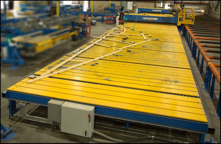
Control Valves
This section describes how valves control individual tables or setups. A table line may
have multiple setups depending on installation requirements.
Setup (noun):
A section of the pneumatic system configured to
act as one unit; it controls the air flow for multiple
table ejectors.
1. A foot valve (new models) or hand valve (also referred to as a pilot valve) is used
to control a setup. See Figure 4-1.
Figure 4-1: Ejector Control Valves
Original Instructions: 001090 rev. C 13Operation
2. The table valves determine whether the ejectors for an individual table functions
within a setup (Figure 4-2).
Figure 4-2: Table Valve
3. Ball valves installed in the 22-mm tubing are used to designate where a setup
(composed of multiple tables) starts and stops (Figure 4-3).
4. The shut-off valve controls air flow to all tables in a setup (Figure 4-3).
Figure 4-3: Setup Ball Valves and Shut-Off Valve
Original Instructions: 001090 rev. C 14You can also read