Rosemount DIN-Style Temperature Sensors and Thermowells (Metric) - Emerson
←
→
Page content transcription
If your browser does not render page correctly, please read the page content below

Product Data Sheet
                                                                             00813-0200-2654, Rev LC
                                                                                           July 2020

Rosemount™ DIN-Style Temperature Sensors
and Thermowells (Metric)

■ RTDs (0065) and thermocouples (0185) available to meet any process requirement
■ DIN-style for easy installation and replacement
■ Integrated temperature assembly with Rosemount transmitters available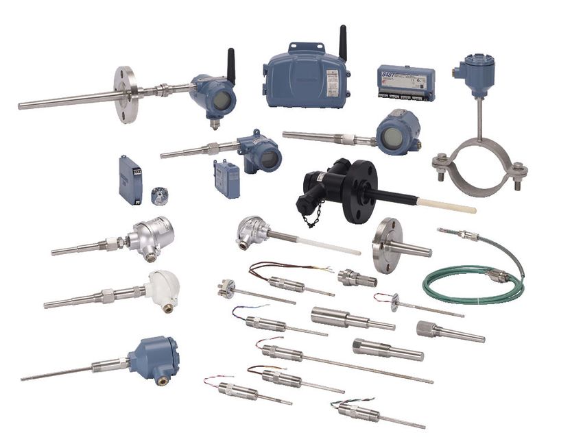
Sensor and Accessories (Metric)                                                                                                                                                    July 2020

Features and benefits
Optimize plant efficiency and increase measurement reliability with industry-proven design and specifications
■ Available in a wide variety of sensing technologies – RTD and thermocouples.
■ All sensor styles and lengths are available in 6 mm diameter.
■ State of the art manufacturing procedures provide robust element packaging and increasing reliability.
■ Industry-leading calibration capabilities allow for Callendar-Van Dusen values to give increased accuracy when paired with
  Rosemount transmitters.
■ Optional Class A accuracy for critical temperature measurement points.

Streamline operations and maintenance with sensor and thermowell design
■ DIN-style sensor uses connection heads that allow quick mounting and replacement while maintaining environmental integrity.
■ Terminal block, flying leads, and spring loaded threaded adapter styles offer remote or integral transmitter mounting
  configuration.

Contents
Features and benefits........................................................................................................................................................................ 2
Rosemount DIN-Style Sensor and Thermowell...................................................................................................................................4
Rosemount Series 96 Barstock Thermowell..................................................................................................................................... 23
Sensor reference information.......................................................................................................................................................... 27
Specifications.................................................................................................................................................................................. 31
Product Certifications......................................................................................................................................................................34
Sensor-to-transmitter matching ..................................................................................................................................................... 40
Accessories......................................................................................................................................................................................46
Wake frequency calculation.............................................................................................................................................................49

2                                                                                                                                                      Emerson.com/Rosemount

July 2020                                                                              Sensor and Accessories (Metric)

Explore the benefits of Complete Point Solutions™ from Emerson
■ An “Assemble Sensor to Specific Transmitter” option enables Emerson to provide a complete point temperature solution,
  delivering an installation-ready transmitter and sensor assembly.
■ Emerson has a complete portfolio of single point and high density temperature measurement solutions, allowing you to
  effectively measure and control your processes with the reliability you trust from Rosemount products.

Experience global consistency and local support from numerous worldwide Rosemount Temperature
manufacturing sites
■ World-class manufacturing provides globally consistent products from every factory and the capacity to fulfill the needs of any
  project, large or small.
■ Experienced instrumentation consultants help select the right product for any temperature application and advise on best
  installation practices.
■ An extensive global network of Emerson service and support personnel can be on-site when and where they are needed.

Access information when you need it with asset tags
Newly shipped devices include a unique QR code asset tag that enables you to access serialized information directly from the
device. With this capability, you can:
■ Access device drawings, diagrams, technical documentation, and troubleshooting information in your MyEmerson account
■ Improve mean time to repair and maintain efficiency
■ Ensure confidence that you have located the correct device
■ Eliminate the time-consuming process of locating and transcribing nameplates to view asset information

Emerson.com/Rosemount                                                                                                               3
Sensor and Accessories (Metric)                                                                                           July 2020

Rosemount DIN-Style Sensor and Thermowell
                                                         The Rosemount DIN-Style Sensor and Thermowell have designs that
                                                         provide flexible and reliable temperature measurements in process
                                                         environments.
                                                         Features include:
                                                         ■ Temperature range of –196 to 450 °C for RTD, –40 to 1000 °C for
                                                            thermocouple
                                                         ■ Industry-standard sensor types, including RTD and thermocouple
                                                           varieties
                                                         ■ DIN-style design for easy mounting and replacement
                                                         ■ Variety of enclosure and connection head options
                                                         ■ Global hazardous-location approvals available
                                                         ■ Calibration services available to give you insight to sensor
                                                           performance
                                                         ■ MID calibration options for custody transfer
                                                         ■ Assemble to transmitter option

                                                               VIEW PRODUCT >

Online Product Configurator
Many products are configurable online using our Product Configurator. Select the Configure button or visit our website to start.
With this tool's built-in logic and continuous validation, you can configure your products more quickly and accurately.

Model codes
Model codes contain the details related to each product. Exact model codes will vary; an example of a typical model code is shown
in Figure 1.
Figure 1: Model Code Example

    1. Required model components (choices available on most)
    2. Additional options (variety of features and functions that may be added to products)

Specifications and options
See the Specifications and options section for more details on each configuration. Specification and selection of product materials,
options, or components must be made by the purchaser of the equipment. See the Material selection section for more information.

4                                                                                                     Emerson.com/Rosemount
July 2020 Sensor and Accessories (Metric) Optimizing lead time The starred offerings (★) represent the most common options and should be selected for best delivery. The non-starred offerings are subject to additional delivery lead time. Series 65 Platinum RTD and 185 Thermocouple without thermowell Required model components Model Code Description 0065 Pt 100 RTD (IEC 751) without thermowell 0185 Thermocouple (IEC 584 Class 1) without thermowell Connection head Code Description IP rating(1) Conduit/cable entry C Rosemount aluminum 66/68 M20 x 1.5 ★ D Rosemount aluminum 66/68 ½-in. NPT ★ 1 Rosemount aluminum with LCD display meter cover 66/68 M20 x1.5 ★ 2 Rosemount aluminum with LCD display meter cover 66/68 ½-in. NPT ★ N No connection head N/A N/A ★ G Rosemount stainless steel 66/68 M20 x 1.5 H Rosemount stainless steel 66/68 ½-in. NPT J GR–A/BL (BUZ) aluminum with cable gland 65 M20 x 1.5 L TZ–A/BL (BUZH) aluminum with cable gland 65 M20 x 1.5 7 Aluminum dual entry head 66 2 x ¾-in. NPT 8 Aluminum dual entry head 66 2 x M20 x 1.5 9 Aluminum dual entry head 66 2 x ½-in. NPT K Stainless steel dual entry head 66 2 x ¾-in. NPT R Stainless steel dual entry head 66 2 x M20 x 1.5 W Stainless steel dual entry head 66 2 x ½-in. NPT A TZ-A/BL (BUZH) aluminum coated 65 M20 x 1.5 P SD-BK N/A M20 x 1.5 (1) To maintain IP rating, use a suitable cable gland on the conduit connection thread. All threads must be sealed with a suitable sealing tape. Emerson.com/Rosemount 5
Sensor and Accessories (Metric)                                                                                         July 2020

Sensor lead wire termination

Code        Description
0           Flying leads (no springs on DIN plate)                                                                            ★
2           Terminal block (DIN 43762)                                                                                        ★
3           Spring loaded adapter (½-in. NPT)                                                                                 ★

Sensor type

Sensor          Code         Description                                                Temperature range
                1            RTD, single element, 4-wire                                –50 to 450 °C (–58 to 842 °F)         ★
                2            RTD, dual element, 3-wire                                  –50 to 450 °C (–58 to 842 °F)         ★
65 only
                3            RTD, single element, 4-wire                                –196 to 300 °C (–321 to 572 °F)       ★
                4            RTD, dual element, 3-wire                                  –196 to 300 °C (–321 to 572 °F)       ★
                03J1         Thermocouple, Type J, single element, ungrounded           –40 to 750 °C (–40 to 1382 °F)        ★
                03K1         Thermocouple, Type K, single element, ungrounded           –40 to 1000 °C (–40 to 1832 °F)       ★
185 only
                05J1         Thermocouple, Type J, dual element, isolated, ungrounded   –40 to 750 °C (–40 to 1382 °F)        ★
                05K1         Thermocouple, Type K, dual element, isolated, ungrounded   –40 to 1000 °C (–40 to 1832 °F)       ★
                7            RTD, single element, 3-wire vibration resistance           –60 to 600 °C (–76 to 1112 °F)
65 only         9            RTD, single element, 4-wire vibration resistance           –60 to 600 °C (–76 to 1112 °F)
                0            RTD, dual element, 3-wire vibration resistance             –60 to 600 °C (–76 to 1112 °F)
                03N1         Thermocouple, Type N, single element, ungrounded           –40 to 1000 °C (–40 to 1832 °F)
185 only
                05N1         Thermocouple, Type N, dual element, isolated, ungrounded   –40 to 1000 °C (–40 to 1832 °F)

Extension

Code       Description                          Head connection        Instrument        Material
                                                                       connection
D          DIN Standard 12 x 1.5                M24 x 1.5              ½-in. NPT         300 series stainless steel           ★
T          DIN Standard 12 x 1.5                M24 x 1.5              M18 x 1.5         300 series stainless steel           ★
F          Nipple-union-nipple                  ½-in. NPT              ½-in. NPT         300 series stainless steel           ★
J          Nipple-union (M/F)                   N/A                    ½-in. NPT         300 series stainless steel           ★
N          No extension (only available with connection head code N)                                                          ★
W          No extension head connection M24 x 1.5                                                                             ★
L          No extension head connection ½-in. NPT                                                                             ★

Extension length (N) in millimeters

Code        Description
0000        No extension (use with extension code N, W, or L)                                                                 ★

6                                                                                                   Emerson.com/Rosemount
July 2020 Sensor and Accessories (Metric) Code Description 0035 35 mm ★ 0080 80 mm (standard for extension type code J) ★ 0110 110 mm (standard for extension type codes F and J) ★ 0135 135 mm (standard for DIN extension used with Rosemount connection head material codes C, D, G, H, 1, and 2) ★ 0150 150 mm (standard for DIN extension used with form B connection head material codes J and L) ★ XXXX Non-standard extension length (available from 35 to 500 mm in 5 mm increments) Thermowell material Code Description N No thermowell ★ Sensor length (L) in millimeters Code Description 0145 145 mm ★ 0205 205 mm ★ 0275 275 mm ★ 0315 315 mm ★ 0375 375 mm ★ 0405 405 mm ★ 0435 435 mm ★ 0555 555 mm ★ XXXX Non-standard sensor length (available from 100 to 9999 mm in 5-mm increments) Additional options Sensor options Available with Series 65 Sensor only. Code Description Temperature range A1 Single element class A sensor –50 to 300 °C (–58 to 572 °F) (0 –350 °C for sensor types 7, 9,0 ) ★ A2 Dual element class A sensor –50 to 300 °C (–58 to 572 °F) (0–350 °C for sensor types 7, 9, 0) ★ Product certifications Refer to Table 3 for limitation on options available with approvals. Code Description I1 ATEX Intrinsic Safety Approval ★ N1 ATEX Type n Approval ★ Emerson.com/Rosemount 7
Sensor and Accessories (Metric)                                                                                 July 2020

Code     Description
E1       ATEX Flameproof Approval                                                                                     ★
ND       ATEX Dust Approval                                                                                           ★
K1       ATEX Flameproof, Intrinsic Safety, Type n, and Dust Approval                                                 ★
E7       IECEx Flameproof Approval                                                                                    ★
E5       US Explosionproof Approval                                                                                   ★
E4       TIIS Flameproof Approval (consult factory for availability)                                                  ★
E6       Canada Explosionproof Approval                                                                               ★
E2       Brazil Flameproof Approval                                                                                   ★
KD       US Explosionproof, Canada Explosionproof, and ATEX Flameproof Approval                                       ★
KM       Technical Regulations Customs Union (EAC) Flameproof, Intrinsic Safety Approval                              ★
IM       Technical Regulations Customs Union (EAC) Intrinsic Safety Approval                                          ★
EM       Technical Regulations Customs Union (EAC) Flameproof Approval                                                ★

Ground screw

Code     Description
G1       External ground screw (only available with Rosemount connection head codes C, D,G,H, 1, and 2)               ★

Cable glands

Code     Description
G2       EEx d, brass, diameter 7.5–11.9 mm
G4       M20 x 1.5 EMV, brass nickel coated, diameter 9–13 mm
G5       M20 x 1.5 EMV, brass nickel coated, diameter 5–13 mm
G7       M20 x 1.5, EEx e, blue, polyamide, diameter 5–9 mm

Cover chain option

Code     Description
G3       Cover chain (only available with Rosemount connection head codes C, D, G, and H)                             ★

Extension ring

Code     Description
G6       Aluminum extension ring for dual transmitter mounting (use with Rosemount connection head codes C and D)     ★

8                                                                                                Emerson.com/Rosemount
July 2020                                                                                Sensor and Accessories (Metric)

Termination

Code        Description
TB          Terminal block for use with sensor termination code 3                                                    ★

Assemble-to option
If ordering Assemble-to option XA with a transmitter, specify the same option on the transmitter model number.

Code        Description
XA          Assemble sensor to specific temperature transmitter (PTFE paste)                                         ★

Sensor calibration with works certificate
Available with 65 only.

Code        Description
V10         Sensor calibration from –50 to 450 °C (–58 to 842 °F) with A, B, C, and Callendar-Van Dusen constants    ★
V11         Sensor calibration from 0 to 100 °C (32 to 212 °F) with A, B, C, and Callendar-Van Dusen constants       ★
X8          Sensor calibration over specified temperature range with A, B, C, and Callendar-Van Dusen constants      ★

VS system calibration
Available with Series 65 Sensor only.

Code        Description
MD1         MID custody transfer, –196 to 0 °C (–321 to 32 °F)                                                       ★
MD2         MID custody transfer, –50 to 100 °C (–58 to 212 °F)                                                      ★
MD3         MID custody transfer, 50 to 200 °C (122 to 392 °F)                                                       ★

GOST calibration certificate

Code        Description
QG          Russian GOST Verification Certificate                                                                    ★

Temperature range option

Code        Description
LT          Special materials to meet extended temperature range of –51 °C (–60 °F)                                  ★

Emerson.com/Rosemount                                                                                                    9
Sensor and Accessories (Metric)                                                                                                                      July 2020

Series 65 Platinum RTD and 185 Thermocouple with tubular thermowell

Required model components
Model

 Code        Description
 0065        Pt 100 RTD (IEC 751) without thermowell
 0185        Thermocouple (IEC 584 Class 1) without thermowell

Connection head

 Code        Description                                                                     IP rating(1)                  Conduit/cable entry
 C           Rosemount aluminum                                                                 66/68                             M20 x 1.5                ★
 D           Rosemount aluminum                                                                 66/68                             ½-in. NPT                ★
 1           Rosemount aluminum with LCD display meter cover                                    66/68                             M20 x1.5                 ★
 2           Rosemount aluminum with LCD display meter cover                                    66/68                             ½-in. NPT                ★
 N           No connection head                                                                   N/A                                N/A                   ★
 G           Rosemount stainless steel                                                          66/68                             M20 x 1.5
 H           Rosemount stainless steel                                                          66/68                             ½-in. NPT
 J           GR–A/BL (BUZ) aluminum with cable gland                                               65                             M20 x 1.5
 L           TZ–A/BL (BUZH) aluminum with cable gland                                              65                             M20 x 1.5
 7           Aluminum dual entry head                                                              66                           2 x ¾-in. NPT
 8           Aluminum dual entry head                                                              66                           2 x M20 x 1.5
 9           Aluminum dual entry head                                                              66                           2 x ½-in. NPT
 K           Stainless steel dual entry head                                                       66                           2 x ¾-in. NPT
 R           Stainless steel dual entry head                                                       66                           2 x M20 x 1.5
 W           Stainless steel dual entry head                                                       66                           2 x ½-in. NPT
 A           TZ-A/BL (BUZH) aluminum coated                                                        65                             M20 x 1.5
 P           SD-BK                                                                                N/A                             M20 x 1.5
(1)   To maintain IP rating, use a suitable cable gland on the conduit connection thread. All threads must be sealed with a suitable sealing tape.

Sensor lead wire termination

 Code        Description
 0           Flying leads (no springs on DIN plate)                                                                                                        ★
 2           Terminal block (DIN 43762)                                                                                                                    ★

10                                                                                                                         Emerson.com/Rosemount
July 2020                                                                              Sensor and Accessories (Metric)

Sensor type

Sensor          Code        Description                                                  Temperature range
                1           RTD, single element, 4-wire                                  –50 to 450 °C (–58 to 842 °F)     ★
                2           RTD, dual element, 3-wire                                    –50 to 450 °C (–58 to 842 °F)     ★
65 only
                3           RTD, single element, 4-wire                                  –196 to 300 °C (–321 to 572 °F)   ★
                4           RTD, dual element, 3-wire                                    –196 to 300 °C (–321 to 572 °F)   ★
                03J1        Thermocouple, Type J, single element, ungrounded             –40 to 750 °C (–40 to 1382 °F)    ★
                03K1        Thermocouple, Type K, single element, ungrounded             –40 to 1000 °C (–40 to 1832 °F)   ★
185 only
                05J1        Thermocouple, Type J, dual element, isolated, ungrounded     –40 to 750 °C (–40 to 1382 °F)    ★
                05K1        Thermocouple, Type K, dual element, isolated, ungrounded     –40 to 1000 °C (–40 to 1832 °F)   ★
                7           RTD, single element, 3-wire vibration resistance             –60 to 600 °C (–76 to 1112 °F)
65 only         9           RTD, single element, 4-wire vibration resistance             –60 to 600 °C (–76 to 1112 °F)
                0           RTD, dual element, 3-wire vibration resistance               –60 to 600 °C (–76 to 1112 °F)
                03N1        Thermocouple, Type N, single element, ungrounded             –40 to 1000 °C (–40 to 1832 °F)
185 only
                05N1        Thermocouple, Type N, dual element, isolated, ungrounded     –40 to 1000 °C (–40 to 1832 °F)

Extension

Code        Description
Y           Tubular, no extension (only available with form GN)                                                            ★
Z           Tubular, with extension (only available with form GB, NAMUR)                                                   ★

Extension length (N) in millimeters

Code        Description
0000        No extension (use with extension code Y)                                                                       ★
0050        50 mm                                                                                                          ★
0065        65 mm                                                                                                          ★
0105        105 mm                                                                                                         ★
0115        115 mm                                                                                                         ★
0130        130 mm                                                                                                         ★
0200        200 mm                                                                                                         ★
0250        250 mm                                                                                                         ★
XXXX        Non-standard extension length (available from 50 to 500 mm in 5 mm increments)

Thermowell material

Code        Description
D           1.4404 (316L SST)                                                                                              ★

Emerson.com/Rosemount                                                                                                      11
Sensor and Accessories (Metric) July 2020 Code Description Y 1.4571 (316Ti SST) ★ Immersion length (U) Code Description 0050 50 mm ★ 0075 75 mm ★ 0100 100 mm ★ 0115 115 mm ★ 0130 130 mm ★ 0150 150 mm ★ 0160 160 mm ★ 0200 200 mm ★ 0220 220 mm ★ 0225 225 mm ★ 0250 250 mm ★ 0280 280 mm ★ 0300 300 mm ★ 0345 345 mm ★ 0400 400 mm ★ XXXX Non-standard immersion length (available from 50 to 2500 mm in 5 mm increments) Thermowell mounting style Code Description Process connections Stem style G02(1) Threaded, tapered R ½-in. (½-in. BSPT) Stepped, NAMUR ★ G04(1) Threaded, tapered R ¾-in. (¾-in. BSPT) Stepped, NAMUR ★ G06(1) Threaded, tapered R 1-in. (1-in. BSPT) Stepped, NAMUR ★ G13(1) Threaded, parallel M27 x 2 Stepped, NAMUR ★ G20(1) Threaded, parallel G ½-in. (½-in. BSPF) Stepped, NAMUR ★ G22(1) Threaded, parallel G ¾-in. (¾-in. BSPF) Stepped, NAMUR ★ G24(1) Threaded, parallel G1 -in. (1-in. BSPF) Stepped, NAMUR ★ G91(1) Threaded, parallel M20 x 1.5 Stepped, NAMUR ★ G31(1) Threaded, parallel M33 x 2 Stepped, NAMUR ★ G38(1) Threaded, tapered ½-in. NPT Stepped, NAMUR ★ G40(1) Threaded, tapered ¾-in. NPT Stepped, NAMUR ★ G42(1) Threaded, tapered 1-in. NPT Stepped, NAMUR ★ 12 Emerson.com/Rosemount
July 2020                                                                                        Sensor and Accessories (Metric)

 Code       Description                                              Process connections                 Stem style
 G52(2)     Threaded, parallel                                       G ½-in. (½-in. BSPF)                Straight, GN, D. 9 x 1 mm          ★
 G92(2)     Threaded, parallel                                       M20 x 1.5                           Straight, GN, D. 9 x 1 mm          ★
 G63(2)     Threaded, parallel                                       G ½-in. (½-in. BSPF)                Straight, GN, D. 11x 2 mm          ★
 G94        Threaded, parallel                                       M20 x 1.5                           Straight, GN, D. 11 x 2 mm         ★
 G72(2)     Threaded, parallel                                       G ½-in. (½-in. BSPF)                Straight, GN, D. 9 x 1 mm          ★
 G95(2)     Threaded, parallel                                       M20 x 1.5                           Straight, GN, D. 9 x 1 mm          ★
 L02(1)     Flanged, RF                                              1-in. 150 lb                        Stepped, NAMUR                     ★
 L08(1)     Flanged, RF                                              1½-in. 150 lb                       Stepped, NAMUR                     ★
 L14(1)     Flanged, RF                                              2-in. 150 lb                        Stepped, NAMUR                     ★
 L20(1)     Flanged, RF                                              1-in. 300 lb                        Stepped, NAMUR                     ★
 L26(1)     Flanged, RF                                              1½-in. 300 lb                       Stepped, NAMUR                     ★
 L32(1)     Flanged, RF                                              2-in. 300 lb                        Stepped, NAMUR                     ★
 H02(1)     Flange, Form B1 according to EN 1092-1                   DN 25 PN 16                         Stepped, NAMUR                     ★
 H08(1)     Flange, Form B1 according to EN 1092-1                   DN 25 PN 25/40                      Stepped, NAMUR                     ★
 H14(1)     Flange, Form B1 according to EN 1092-1                   DN 40 PN 16                         Stepped, NAMUR                     ★
 H20(1)     Flange, Form B1 according to EN 1092-1                   DN 40 PN 25/40                      Stepped, NAMUR                     ★
 H26(1)     Flange, Form B1 according to EN 1092-1                   DN 50 PN 40                         Stepped, NAMUR                     ★
(1)   The NAMUR stepped profile is available in both thermowell material options, however to maintain NAMUR compliance material code Y is
      required. 115 mm is the minimum immersion length stepped thermowells are available and is the minimum requirement to maintain NAMUR
      compliance however for lengths shorter than 115 mm a straight thermowell with a 8 mm OD will be provided.
(2)   Not available with thermowell Material code D.

Additional options
Sensor options
Available with Series 65 Sensor only.

 Code       Description                                         Temperature range
 A1         Single element class A sensor                       –50 to 300 °C (–58 to 572 °F) (0 –350 °C for sensor types 7, 9,0 )          ★
 A2         Dual element class A sensor                         –50 to 300 °C (–58 to 572 °F) (0–350 °C for sensor types 7, 9, 0)           ★

Product certifications
Refer to Table 3 for limitation on options available with approvals.

 Code       Description
 I1         ATEX Intrinsic Safety Approval                                                                                                  ★
 N1         ATEX Type n Approval                                                                                                            ★
 E1         ATEX Flameproof Approval                                                                                                        ★
 ND         ATEX Dust Approval                                                                                                              ★
 K1         ATEX Flameproof, Intrinsic Safety, Type n, and Dust Approval                                                                    ★

Emerson.com/Rosemount                                                                                                                       13
Sensor and Accessories (Metric) July 2020 Code Description E7 IECEx Flameproof Approval ★ E5 US Explosionproof Approval ★ E4 TIIS Flameproof Approval (consult factory for availability) ★ E6 Canada Explosionproof Approval ★ E2 Brazil Flameproof Approval ★ KD US Explosionproof, Canada Explosionproof, and ATEX Flameproof Approval ★ KM Technical Regulations Customs Union (EAC) Flameproof, Intrinsic Safety Approval ★ IM Technical Regulations Customs Union (EAC) Intrinsic Safety Approval ★ EM Technical Regulations Customs Union (EAC) Flameproof Approval ★ Ground screw Code Description G1 External ground screw (only available with Rosemount connection head codes C, D,G,H, 1, and 2) ★ Cable glands Code Description G2 EEx d, brass, diameter 7.5–11.9 mm G4 M20 x 1.5 EMV, brass nickel coated, diameter 9–13 mm G5 M20 x 1.5 EMV, brass nickel coated, diameter 5–13 mm G7 M20 x 1.5, EEx e, blue, polyamide, diameter 5–9 mm Cover chain option Code Description G3 Cover chain (only available with Rosemount connection head codes C, D, G, and H) ★ Extension ring Code Description G6 Aluminum extension ring for dual transmitter mounting (use with Rosemount connection head codes C and D) ★ Material certification Code Description Q8 Thermowell material certification, DIN EN 10204 3.1 ★ 14 Emerson.com/Rosemount
July 2020                                                                                Sensor and Accessories (Metric)

External pressure test

Code        Description
R01         Thermowell external pressure testing                                                                     ★

Dye test

Code        Description
R03         Thermowell dye penetration testing                                                                       ★

Assemble-to option
If ordering Assemble-to option XA with a transmitter, specify the same option on the transmitter model number.

Code        Description
XA          Assemble sensor to specific temperature transmitter (PTFE paste)                                         ★

Sensor calibration with works certificate
Available with 65 only.

Code        Description
V10         Sensor calibration from –50 to 450 °C (–58 to 842 °F) with A, B, C, and Callendar-Van Dusen constants    ★
V11         Sensor calibration from 0 to 100 °C (32 to 212 °F) with A, B, C, and Callendar-Van Dusen constants       ★
X8          Sensor calibration over specified temperature range with A, B, C, and Callendar-Van Dusen constants      ★

Temperature range option

Code        Description
LT          Special materials to meet extended temperature range of –51 °C (–60 °F)                                  ★

Emerson.com/Rosemount                                                                                                15
Sensor and Accessories (Metric)                                                                                                                      July 2020

Series 65 Platinum RTD and 185 Thermocouple with barstock thermowell

Required model components
Model

 Code        Description
 0065        Pt 100 RTD (IEC 751) without thermowell
 0185        Thermocouple (IEC 584 Class 1) without thermowell

Connection head

 Code        Description                                                                     IP rating(1)                  Conduit/cable entry
 C           Rosemount aluminum                                                                 66/68                             M20 x 1.5                ★
 D           Rosemount aluminum                                                                 66/68                             ½-in. NPT                ★
 1           Rosemount aluminum with LCD display meter cover                                    66/68                             M20 x1.5                 ★
 2           Rosemount aluminum with LCD display meter cover                                    66/68                             ½-in. NPT                ★
 N           No connection head                                                                   N/A                                N/A                   ★
 G           Rosemount stainless steel                                                          66/68                             M20 x 1.5
 H           Rosemount stainless steel                                                          66/68                             ½-in. NPT
 J           GR–A/BL (BUZ) aluminum with cable gland                                               65                             M20 x 1.5
 L           TZ–A/BL (BUZH) aluminum with cable gland                                              65                             M20 x 1.5
 7           Aluminum dual entry head                                                              66                           2 x ¾-in. NPT
 8           Aluminum dual entry head                                                              66                           2 x M20 x 1.5
 9           Aluminum dual entry head                                                              66                           2 x ½-in. NPT
 K           Stainless steel dual entry head                                                       66                           2 x ¾-in. NPT
 R           Stainless steel dual entry head                                                       66                           2 x M20 x 1.5
 W           Stainless steel dual entry head                                                       66                           2 x ½-in. NPT
 A           TZ-A/BL (BUZH) aluminum coated                                                        65                             M20 x 1.5
 P           SD-BK                                                                                N/A                             M20 x 1.5
(1)   To maintain IP rating, use a suitable cable gland on the conduit connection thread. All threads must be sealed with a suitable sealing tape.

Sensor lead wire termination

 Code        Description
 0           Flying leads (no springs on DIN plate)                                                                                                        ★
 2           Terminal block (DIN 43762)                                                                                                                    ★
 3           Spring loaded adapter (½-in. NPT)                                                                                                             ★

16                                                                                                                         Emerson.com/Rosemount
July 2020                                                                              Sensor and Accessories (Metric)

Sensor type

Sensor          Code        Description                                                   Temperature range
                1           RTD, single element, 4-wire                                   –50 to 450 °C (–58 to 842 °F)     ★
                2           RTD, dual element, 3-wire                                     –50 to 450 °C (–58 to 842 °F)     ★
65 only
                3           RTD, single element, 4-wire                                   –196 to 300 °C (–321 to 572 °F)   ★
                4           RTD, dual element, 3-wire                                     –196 to 300 °C (–321 to 572 °F)   ★
                03J1        Thermocouple, Type J, single element, ungrounded              –40 to 750 °C (–40 to 1382 °F)    ★
                03K1        Thermocouple, Type K, single element, ungrounded              –40 to 1000 °C (–40 to 1832 °F)   ★
185 only
                05J1        Thermocouple, Type J, dual element, isolated, ungrounded      –40 to 750 °C (–40 to 1382 °F)    ★
                05K1        Thermocouple, Type K, dual element, isolated, ungrounded      –40 to 1000 °C (–40 to 1832 °F)   ★
                7           RTD, single element, 3-wire vibration resistance              –60 to 600 °C (–76 to 1112 °F)
65 only         9           RTD, single element, 4-wire vibration resistance              –60 to 600 °C (–76 to 1112 °F)
                0           RTD, dual element, 3-wire vibration resistance                –60 to 600 °C (–76 to 1112 °F)
                03N1        Thermocouple, Type N, single element, ungrounded              –40 to 1000 °C (–40 to 1832 °F)
185 only
                05N1        Thermocouple, Type N, dual element, isolated, ungrounded      –40 to 1000 °C (–40 to 1832 °F)

Extension

Code       Description                  Head connection                Instrument connection     Materials
D          DIN standard 12 x 1.5        M24 x 1.5                      ½-in. NPT                 300 SST                    ★
T          DIN standard 12 x 1.5        M24 x 1.5                      M18 x 1.5                 300 SST                    ★
F          Nipple-union-nipple          ½-in. NPT                      ½-in. NPT                 300 SST                    ★
J          Nipple-union (M/F)           None                           ½-in. NPT                 300 SST                    ★
N          No extension (only available with connection head code N)                                                        ★

Extension length (N) in millimeters

Code        Description
0000        No extension (use with extension code N, W, or L)                                                               ★
0035        35 mm                                                                                                           ★
0080        80 mm (standard for extension type code J)                                                                      ★
0110        110 mm (standard for extension type codes F and J)                                                              ★
0135        135 mm (standard for DIN extension used with Rosemount connection head material codes C, D, G, H, 1, and 2)     ★
0150        150 mm (standard for DIN extension used with form B connection head material codes J and L)                     ★
XXXX        Non-standard extension length (available from 35 to 500 mm in 5 mm increments)

Emerson.com/Rosemount                                                                                                       17
Sensor and Accessories (Metric) July 2020 Thermowell material Code Description D 1.4404 (316L SST) ★ Y 1.4571 (316Ti SST) ★ A 1.4401 (316 SST) J 2.4819 (Alloy C-276) K 1.5415 (A 204 Size A) P 1.7380 (A 182-Grade F22) Z 1.7335 (A 182-Grade F11) Immersion length Code Description 0065 65 mm ★ 0075 75 mm ★ 0115 115 mm ★ 0125 125 mm ★ 0150 150 mm ★ 0225 225 mm ★ 0300 300 mm ★ 0450 450 mm ★ XXXX Non-standard immersion length (available from 50 to 1000 mm in 5 mm increments) Thermowell mounting style Code Description Process connection Stem style T08 Threaded R ½-in. (½-in. BSPT) Tapered ★ T10 Threaded R ¾-in. (¾-in.BSPT) Tapered ★ T12 Threaded R 1-in. (1-in. BSPT) Tapered ★ T26(1) Threaded G ½-in. (½-in. BSPF) Tapered ★ T28(1) Threaded G ¾-in. (¾-in.BSPF) Tapered ★ T30(1) Threaded G 1-in. (1-in. BSPF) Tapered ★ T44 Threaded ½-in. NPT Tapered ★ T46 Threaded ¾-in. NPT Tapered ★ T48 Threaded 1-in. NPT Tapered ★ T93(1) Threaded M27 x 2 Tapered ★ T95(1) Threaded M33 x 2 Tapered ★ T98(1) Threaded M20 x 1.5 Tapered ★ 18 Emerson.com/Rosemount
July 2020                                                                                         Sensor and Accessories (Metric)

 Code            Description                                                 Process connection         Stem style
 F04             Flanged, RF                                                 1-in. 150 lb               Tapered               ★
 F10             Flanged, RF                                                 1½-in. 150 lb              Tapered               ★
 F16             Flanged, RF                                                 2-in. 150 lb               Tapered               ★
 F22             Flanged, RF                                                 1-in. 300 lb               Tapered               ★
 F28             Flanged, RF                                                 1½-in. 300 lb              Tapered               ★
 F34             Flanged, RF                                                 2-in. 300 lb               Tapered               ★
 F40             Flanged, RF                                                 1-in. 600 lb               Tapered               ★
 F46             Flanged, RF                                                 1½-in. 600 lb              Tapered               ★
 F52             Flanged, RF                                                 2-in. 600 lb               Tapered               ★
 F58(2)          Flanged, RF                                                 1-in. 900/1500 lb          Tapered               ★
 F64(2)          Flanged, RF                                                 1½-in. 900/1500 lb         Tapered               ★
 F70(2)(3)       Flanged, RF                                                 2-in. 900/1500 lb          Tapered               ★
 F82(2)(3)       Flanged, RF                                                 1½-in. 2500 lb             Tapered               ★
 F88(2)(3)       Flanged, RF                                                 2-in. 2500 lb              Tapered               ★
 D04             Flange, Form B1 according to EN 1092-1                      DN 25 PN 16                Tapered               ★
 D10             Flange, Form B1 according to EN 1092-1                      DN 25 PN 25/40             Tapered               ★
 D16             Flange, Form B1 according to EN 1092-1                      DN 40 PN 16                Tapered               ★
 D22             Flange, Form B1 according to EN 1092-1                      DN 40 PN 25/40             Tapered               ★
 D28             Flange, Form B1 according to EN 1092-1                      DN 50 PN 40                Tapered               ★
 W10             Welded                                                      ¾-in. pipe                 Tapered               ★
 W12             Welded                                                      1-in. pipe                 Tapered               ★
 W14             Welded                                                      1¼-in. pipe                Tapered               ★
 W16             Welded                                                      1½-in. pipe                Tapered               ★
 E01(4)(5)       D1 welded                                                   24h7                       Tapered               ★
 E02(4)(5)       D2 welded                                                   24h7                       Tapered               ★
 E04(4)(6)       D4 welded                                                   24h7                       Tapered               ★
 E05(6)          D5 welded                                                   24h7                       Tapered               ★
(1)   This mounting style is only available with the lagging length code T040.
(2)   Full penetration weld option R07 is required with this mounting style.
(3)   This mounting style has a minimum lagging length of 80 mm.
(4)   Only available with eztension style T.
(5)   This mounting style is only available with the lagging length code T075.
(6)   This mounting style is only available with the lagging length code T135.

Emerson.com/Rosemount                                                                                                         19
Sensor and Accessories (Metric)                                                                                                 July 2020

Additional options
Sensor options
Available with Series 65 Sensor only.

Code      Description                                      Temperature range
A1        Single element class A sensor                    –50 to 300 °C (–58 to 572 °F) (0 –350 °C for sensor types 7, 9,0 )         ★
A2        Dual element class A sensor                      –50 to 300 °C (–58 to 572 °F) (0–350 °C for sensor types 7, 9, 0)          ★

Product certifications
Refer to Table 3 for limitation on options available with approvals.

Code      Description
I1        ATEX Intrinsic Safety Approval                                                                                              ★
N1        ATEX Type n Approval                                                                                                        ★
E1        ATEX Flameproof Approval                                                                                                    ★
ND        ATEX Dust Approval                                                                                                          ★
K1        ATEX Flameproof, Intrinsic Safety, Type n, and Dust Approval                                                                ★
E7        IECEx Flameproof Approval                                                                                                   ★
E5        US Explosionproof Approval                                                                                                  ★
E4        TIIS Flameproof Approval (consult factory for availability)                                                                 ★
E6        Canada Explosionproof Approval                                                                                              ★
E2        Brazil Flameproof Approval                                                                                                  ★
KD        US Explosionproof, Canada Explosionproof, and ATEX Flameproof Approval                                                      ★
KM        Technical Regulations Customs Union (EAC) Flameproof, Intrinsic Safety Approval                                             ★
IM        Technical Regulations Customs Union (EAC) Intrinsic Safety Approval                                                         ★
EM        Technical Regulations Customs Union (EAC) Flameproof Approval                                                               ★

Ground screw

Code      Description
G1        External ground screw (only available with Rosemount connection head codes C, D,G,H, 1, and 2)                              ★

Cable glands

Code      Description
G2        EEx d, brass, diameter 7.5–11.9 mm
G4        M20 x 1.5 EMV, brass nickel coated, diameter 9–13 mm
G5        M20 x 1.5 EMV, brass nickel coated, diameter 5–13 mm
G7        M20 x 1.5, EEx e, blue, polyamide, diameter 5–9 mm

20                                                                                                       Emerson.com/Rosemount
July 2020                                                                             Sensor and Accessories (Metric)

Cover chain option

Code        Description
G3          Cover chain (only available with Rosemount connection head codes C, D, G, and H)                           ★

Extension ring

Code        Description
G6          Aluminum extension ring for dual transmitter mounting (use with Rosemount connection head codes C and D)   ★

Termination

Code        Description
TB          Terminal block for use with sensor termination code 3                                                      ★

Material certification

Code        Description
Q8          Thermowell material certification, DIN EN 10204 3.1                                                        ★

External pressure test

Code        Description
R01         Thermowell external pressure testing                                                                       ★

Internal pressure test

Code        Description
R22         Thermowell internal pressure testing                                                                       ★

Dye test

Code        Description
R03         Thermowell dye penetration testing                                                                         ★

NACE approval
Only available with thermowell material codes D, J, and A.

Code        Description
R05         Thermowell NACE approval                                                                                   ★

Emerson.com/Rosemount                                                                                                  21
Sensor and Accessories (Metric)                                                                                   July 2020

Assemble-to option
If ordering Assemble-to option XA with a transmitter, specify the same option on the transmitter model number.

Code      Description
XA        Assemble sensor to specific temperature transmitter (PTFE paste)                                              ★

Sensor calibration with works certificate
Available with 65 only.

Code      Description
V10       Sensor calibration from –50 to 450 °C (–58 to 842 °F) with A, B, C, and Callendar-Van Dusen constants         ★
V11       Sensor calibration from 0 to 100 °C (32 to 212 °F) with A, B, C, and Callendar-Van Dusen constants            ★
X8        Sensor calibration over specified temperature range with A, B, C, and Callendar-Van Dusen constants           ★

VS system calibration
Available with Series 65 Sensor only.

Code      Description
MD1       MID custody transfer, –196 to 0 °C (–321 to 32 °F)                                                            ★
MD2       MID custody transfer, –50 to 100 °C (–58 to 212 °F)                                                           ★
MD3       MID custody transfer, 50 to 200 °C (122 to 392 °F)                                                            ★

Temperature range option

Code      Description
LT        Special materials to meet extended temperature range of –51 °C (–60 °F)                                       ★

22                                                                                                   Emerson.com/Rosemount
July 2020                                                                                Sensor and Accessories (Metric)

Rosemount Series 96 Barstock Thermowell
                                                                  The Rosemount Series 96 Barstock Thermowell has designs that
                                                                  provide flexible and reliable temperature measurements in
                                                                  process environments.
                                                                  Features include:
                                                                  ■ Threaded, flanged, and weld-in styles
                                                                  ■ Wake frequency calculations conforming to ASME PTC 19.3
                                                                  ■ NACE approval available
                                                                  ■ Variety of testing and certification options available

                                                                        VIEW PRODUCT >

Online Product Configurator
Many products are configurable online using our Product Configurator. Select the Configure button or visit our website to start.
With this tool's built-in logic and continuous validation, you can configure your products more quickly and accurately.

Model codes
Model codes contain the details related to each product. Exact model codes will vary; an example of a typical model code is shown
in Figure 1.
Figure 2: Model Code Example

   1. Required model components (choices available on most)
   2. Additional options (variety of features and functions that may be added to products)

Specifications and options
See the Specifications and options section for more details on each configuration. Specification and selection of product materials,
options, or components must be made by the purchaser of the equipment. See the Material selection section for more information.

Optimizing lead time
The starred offerings (★) represent the most common options and should be selected for best delivery. The non-starred offerings
are subject to additional delivery lead time.

Emerson.com/Rosemount                                                                                                              23
Sensor and Accessories (Metric) July 2020 Required model components Model Code Description 0096 Barstock thermowell ★ Thermowell material Additional materials are available upon request. Code Description D 1.4404 (316L SST) ★ Y 1.4571 (316Ti SST) ★ A 1.4401 (316 SST) J 2.4819 (Alloy C-276) K 1.5415 (204 Size A) P 1.7380 (182 Grade-F22) Z 1.7335 (182 Grade-F11) Immersion length (L) in millimeters Code Description 0065 65 mm (standard length for weld-in thermowells, E01 and E04) ★ 0075 75 mm ★ 0115 115 mm ★ 0125 125 mm (standard length for weld-in thermowells, E02 and E05) ★ 0150 150 mm ★ 0225 225 mm ★ 0300 300 mm ★ 0450 450 mm ★ XXXX Non-standard immersion length (available from 25 to 1000 mm in 5-mm increments) Thermowell mounting style Code Description Process connection Stem style T08 Thread R ½-in. (½-in. BSPT) Tapered ★ T10 Thread R ¾-in. (¾-in.BSPT) Tapered ★ T12 Thread R 1-in. (1-in. BSPT) Tapered ★ T26(1) Thread G ½-in. (½-in. BSPF) Tapered ★ T28(1) Thread G ¾-in. (¾-in.BSPF) Tapered ★ 24 Emerson.com/Rosemount
July 2020                                                                                               Sensor and Accessories (Metric)

 Code             Description                                                    Process connection              Stem style
 T30(1)           Thread                                                         G 1-in. (1-in. BSPF)            Tapered            ★
 T44              Thread                                                         ½-in. NPT                       Tapered            ★
 T46              Thread                                                         ¾-in. NPT                       Tapered            ★
 T48              Thread                                                         1-in. NPT                       Tapered            ★
 T93(1)           Thread                                                         M27 X 2                         Tapered            ★
 T95(1)           Thread                                                         M33 X 2                         Tapered            ★
 T98(1)           Thread                                                         M20 X 1.5                       Tapered            ★
 F04              Flange, RF                                                     1-in. 150 lb                    Tapered            ★
 F10              Flange, RF                                                     1½-in. 150 lb                   Tapered            ★
 F16              Flange, RF                                                     2-in. 150 lb                    Tapered            ★
 F22              Flange, RF                                                     1-in. 300 lb                    Tapered            ★
 F28              Flange, RF                                                     1½-in. 300 lb                   Tapered            ★
 F34              Flange, RF                                                     2-in. 300 lb                    Tapered            ★
 F40              Flange, RF                                                     1-in. 600 lb                    Tapered            ★
 F46              Flange, RF                                                     1½-in. 600 lb                   Tapered            ★
 F52              Flange, RF                                                     2-in. 600 lb                    Tapered            ★
 F58(2)           Flanged, RF                                                    1-in. 900/1500 lb               Tapered            ★
 F64(1)           Flanged, RF                                                    1½-in. 900/1500 lb              Tapered            ★
 F70(1)(3)        Flanged, RF                                                    2-in. 900/1500 lb               Tapered            ★
 F82(1)(3)        Flanged, RF                                                    1½-in 2500 lb                   Tapered            ★
 F88(1)(3)        Flanged, RF                                                    2-in. 2500 lb                   Tapered            ★
 D04              Flange, Form B1 according to EN 1092-1                         DN 25 PN 16                     Tapered            ★
 D10              Flange, Form B1 according to EN 1092-1                         DN 25 PN 25/40                  Tapered            ★
 D16              Flange, Form B1 according to EN 1092-1                         DN 40 PN 16                     Tapered            ★
 D22              Flange, Form B1 according to EN 1092-1                         DN 40 PN 25/40                  Tapered            ★
 D28              Flange, Form B1 according to EN 1092-1                         DN 50 PN 40                     Tapered            ★
 W10              Welded                                                         ¾-in. pipe                      Tapered            ★
 W12              Welded                                                         1-in. pipe                      Tapered            ★
 W14              Welded                                                         1¼-in. pipe                     Tapered            ★
 W16              Welded                                                         1½-in. pipe                     Tapered            ★
 E01(4)           D1 welded, DIN                                                 24h7                            Tapered            ★
 E02(4)           D2 welded, DIN                                                 24h7                            Tapered            ★
 E04(5)           D4 welded, DIN                                                 24h7                            Tapered            ★
 E05(5)           D5 welded, DIN                                                 24h7                            Tapered            ★
(1)   This mounting style is only available with the lagging length code T040.
(2)   Full penetration weld option R07 is required with this mounting style.
(3)   This mounting style has a minimum lagging length of 80 mm.

Emerson.com/Rosemount                                                                                                               25
Sensor and Accessories (Metric)                                                                    July 2020

(4)   This mounting style is only available with the lagging length code T075.
(5)   This mounting style is only available with the lagging length code T135.

Lagging length

 Code        Description
 T040        40 mm                                                                                       ★
 T060        60 mm                                                                                       ★
 T075        75 mm                                                                                       ★
 T080        80 mm                                                                                       ★
 T135        135 mm                                                                                      ★
 TXXX        Non standard lagging length

Instrument connection thread type

 Code        Description
 A           M24 x 1.5                                                                                   ★
 D           ½-in. NPT                                                                                   ★
 T           M18 x 1.5 (valid for weld-in thermowells codes E01, E02, E04, and E05)                      ★

Additional options

Material certification

 Code        Description
 Q8          Thermowell material certification, DIN EN 10204 3.1                                         ★

External pressure test

 Code        Description
 R01         Thermowell external pressure testing                                                        ★

Internal pressure test

 Code        Description
 R22         Thermowell internal pressure testing                                                        ★

Dye test

 Code        Description
 R03         Thermowell dye penetration testing                                                          ★

26                                                                                    Emerson.com/Rosemount
July 2020                                                                                  Sensor and Accessories (Metric)

NACE approval
Only available with thermowell material codes D, J, and A.

Code        Description
R05         Thermowell NACE approval                                                                                                 ★

Plug/chain

Code        Description
R06         Stainless steel plug and chain                                                                                           ★

Weld option

Code        Description
R07         Full penetration weld - for flanged thermowells only                                                                     ★

Flange type

Code        Description
R16         Ring joint flange face                                                                                                   ★

Wake frequency calculation

Code        Description
R21         Wake frequency (thermowell strength calculation)                                                                         ★

Sensor reference information
Overview
Rosemount integral mount temperature sensors, accessory hardware, and assemblies constitute a complete line of industrial
temperature-sensing instruments. A variety of RTD and thermocouple sensors are available alone, or as complete assemblies
including connection heads, thermowells, and extension fittings. Emerson offers complete temperature measurement assemblies
including Rosemount Smart and Programmable Temperature Transmitters. Ask your Emerson representative for details.
Series 65 Platinum RTD Temperature Sensors are highly linear and have a stable resistance versus temperature relationship. These
sensors are used primarily in industrial environments where high accuracy, durability, and long-term stability are required. Series 65
Sensors are designed to meet the most critical parameters of international standards: IEC 751:1983, Amendment 1:1986 and
2:1995 and DIN EN 60751:1996. This standardization provides sensor interchangeability without the need for transmitter circuitry
adjustment.
Enhanced performance and optimal temperature measurement accuracy is available for Series 65 Sensors coupled with a range of
Rosemount Temperature Transmitters through calibration schedules and Callendar-Van Dusen constants.
Series 185 Thermocouple Temperature Sensors conform to IEC 584:1982, Amendment 1:1989 and are available in types J, K and N.
Series 185 Sensors are available single ungrounded, or dual ungrounded, isolated.
All sensors are available in a variety of lengths(1) and ranges with flying lead, terminal block, or ½-in. NPT spring-loaded adapter lead
wire terminations.

Emerson.com/Rosemount                                                                                                                 27
Sensor and Accessories (Metric)                                                                                                      July 2020

In addition to complete assemblies, Emerson offers a selection of separate accessory hardware including connection heads and
thermowells.

Selecting an extension and thermowell
Aside from ambient temperature variations, heat from the process, in a direct mounting configuration, is transferred from the
thermowell to the transmitter housing. If the expected process temperature is near or beyond the transmitter specification limits,
consider the use of additional thermowell extension length, an extension nipple, or a remote mounting configuration to isolate the
transmitter from these excessive temperatures. Figure 3 provides an example of the relationship between transmitter housing
temperature rise and extension length. Use Figure 3 and the accompanying example as a guide for determining adequate
thermowell extension length.
Figure 3: Transmitter Housing Temperature Rise vs. Uninsulated Extension Length
                                   60
Housing Rise Above Ambient (°C)

                                   50
                                               815

                                   40
                                                   °
                                                  CP
                                                    ro

                                   30
                                                       ce

                                                             ss
                                                                  Te
                                             54

                                                                       mp
                                              0°

                                                                          erat
                                                                              u re
                                                C

                                   20                  ro
                                                    P

                                                            ce
                                                                 ss T
                                                                     emp
                                             25                          era
                                                                       ture
                                               0°
                                   10               C Pr o
                                                             c ess Temperature

                                    0
                                        75        100             125        150     175   200   225

                                              Uninsulated Extension “N” Length (mm)

Example
The rated ambient temperature specification for the transmitter is 85 °C. If the maximum ambient temperature is 40 °C and the
temperature to be measured is 540 °C, the maximum allowable housing temperature rise is the rated temperature specification
limit minus the existing ambient temperature (85 – 40 °F), or 45 °C.
As shown in Figure 3, an “N” dimension of 90 mm will result in a housing temperature rise of 22 °C. An “N” dimension of 100 mm
would therefore be the minimum recommended length, and would provide a safety factor of about 25 °C. A longer “N” dimension,
such as 150 mm, would be desirable in order to reduce errors caused by transmitter temperature effect, although in that case the
transmitter may require extra support.

Integral mount sensors and assemblies
Series 65 RTD and Series 185 Thermocouple Temperature Sensors may be ordered as complete assemblies, which provide a
complete, yet simple, means of specifying the proper industrial hardware for most temperature measurements. One assembly
model number, derived from one ordering table, completely defines the type of sensing element, as well as the material, length,
and style of extension fittings and thermowells.
All sensor assemblies are sized and inspected by Emerson to ensure complete component compatibility and performance.

                                  (1) Sensors over one meter long will be supplied coiled unless otherwise requested.

28                                                                                                                      Emerson.com/Rosemount
July 2020 Sensor and Accessories (Metric) Mounting configurations Series 65 Platinum RTDs and Series 185 Thermocouples You may order the Series 65 RTDs and the Series 185 Thermocouples with flying leads, a terminal block, or a ½-in. NPT spring- loaded adapter. Ordered with flying leads, the sensors are designed to be used with a head mount temperature transmitter attached directly to the sensor. The flying lead configuration allows the removal of the sensor and transmitter as one assembly. The BUZH connection head allows terminal block style sensors and transmitters to be mounted together. The transmitters in these assemblies will be mounted in the cover of the BUZH connection head. The sensors with a ½-in. NPT spring-loaded adapter are used with directly mounted Rosemount 3144P Field Mount Temperature Transmitters or through the use of Rosemount connection heads. This assembly requires a terminal block to be mounted inside the head. Hazardous area approvals are available with all three types of sensors, but they are dependent on the configuration of the entire temperature measurement assembly (see Product Certifications). Temperature considerations Ambient temperature limits for the connection head are –40 °C to +85 °C. The LT option may be extended down to a range of –51 °C to +85 °C. Ambient temperature range addresses the connection head only, and requires suitable cable glands and field wiring provisions to meet the temperature requirements below –40 °C. Emerson.com/Rosemount 29
Sensor and Accessories (Metric)                                                                                                         July 2020

Figure 4: Series 65 RTD Lead Wire Configuration

      Series 65 RTD flying leads and spring-loaded adapter-
                  termination codes 0 or 3 only
          Single element                         Dual element
                                 Wht
                                 Wht

                                 Red
                                 Red

        Series 65 RTD terminal block termination code 2
          Single element                        Dual element(1)

  Red        4                                 3 Red
  Red        3
                                               2 Red
 Wht         1                                 1Wht
                         1       3                              2
                                                            1       3

                         6       4
 Wht         6                                 6 Red        6
                                                                5
                                                                    4

                                               5 Red
                                                4 Wht

(1)   The color of the terminal posts in the terminal block may not match the color of the lead wires connected to the capsule.

Figure 5: Series 185 Lead Wire Configuration

          Series 185 RTD thermocouple terminal block
          Single element                         Dual element
           3 (-)                                  3 (-)

           1 (+)                                  1 (+)
                     1       3                             1        3

                                                           6        4

                                                  6 (-)
                                                  4 (+)

30                                                                                                                         Emerson.com/Rosemount
July 2020 Sensor and Accessories (Metric) Specifications Series 65 Platinum RTD 100 Ω RTD at 0 °C, α = 0.00385 °C-1 Temperature range –50 to 450 °C or –196 to 300 °C depending on type Self heating 0.15 °C/mW when measured per method defined in IEC 751:1983, Amendments 1 and 2 Thermal response time 9 seconds maximum required to reach 50 percent sensor response when tested in flowing water according to IEC 751:1983, Amendments 1 and 2 Immersion error 60 mm minimum usable depth of immersion when tested according to IEC 751:1983, Amendments 1 and 2 Insulation resistance 1,000 MΩ minimum insulation resistance when measured at 500 Vdc and at room temperature Sheath material 316 SST sensor tip (hot end) with 321SST mineral insulated cable construction Lead wire PTFE insulated, silver-coated, 0.21mm2 (24 AWG) stranded copper wire. See Figure 4 for wire configuration. Identification data The model and serial numbers are marked on each sensor. Ingress protection (IP) ratings The Rosemount connection head is rated to IP66/IP68 and NEMA® 4X. The BUZ and BUZH connection heads are rated to IP65. To maintain IP rating at installation, one of the following options must be used with the connection head: ■ Extension and/or adapter and barstock thermowell ■ Tubular thermowell ■ Sensor and sealing screw (extension option “V”) ■ General purpose adapter Emerson.com/Rosemount 31
Sensor and Accessories (Metric)                                                                                          July 2020

Vibration limits
For sensor types option code “1”, “2”, “3”, and “4”, the vibration resistance is ±0.02 percent (0.05 °C) maximum ice-point
resistance shift after 3 g vibration between 10 and 500 Hz for 150 hours according to IEC 751:1983, Amendments 1 and 2.
For sensor types option code “7”, “9”, and “0”, the vibration resistance is ±0.02 percent (0.05 °C) maximum ice-point resistance
shift after 10 g vibration between 10 and 500 Hz for 150 hours according to IEC 751:1983, Amendments 1 and 2.
Table 1: Series 65 Interchangeability

Standard series 65 IEC-751 class B           Temperature
±0.80 °C (±1.44 °F)                          –100 °C (–148 °F)
±0.30 °C (±0.54 °F)                          0 °C (32 °F)
±0.80 °C (±1.44 °F)                          100 °C (212 °F)
±1.80 °C (±3.24 °F)                          300 °C (572 °F)
±2.30 °C (±4.14 °F)                          400 °C (752 °F)
Series 65 with IEC-751 class A option        Temperature
±0.35 °C (±0.63 °F)                          –100 °C (–148 °F)
±0.15 °C (±0.27 °F)                          0 °C (32 °F)
±0.35 °C (±0.63 °F)                          100 °C (212 °F)
±0.75 °C (±1.35 °F)                          300 °C (572 °F)

Series 185 Thermocouple
Construction
A thermocouple consists of a junction between two dissimilar metals that produces a change in thermoelectric emf in relationship
to a change in temperature. Rosemount Series 185 thermocouple sensors are manufactured from selected materials to meet IEC
584 Tolerance Class 1. The junction of these wires is welded to form a pure joint, maintaining the integrity of the circuit and
ensuring the highest accuracy. Ungrounded junctions are protected from the environment by the sensor sheath. The ungrounded
and isolated junctions provide electrical isolation from the sensor sheath.

Sheath material
Rosemount thermocouples are made of a mineral insulated cable design with a variety of sheath materials available to suit both the
temperature and the environment. For temperatures up to 800 °C in air, 1.4541 (321 SST) is standard. For temperatures from 800
to 1100 °C in air, 2.4816 (Alloy 600) is standard. For temperatures above 1100 °C, precious metal or ceramic protective sheaths are
available upon request. For strongly oxidising or reducing atmospheres, consult your local Emerson representative.

Lead wires
PTFE insulated, 0.52 mm2 (20 AWG) stranded thermocouple wire. Color coded per IEC 584. See Figure 5 for wire configuration.

Identification data
The model and serial numbers are marked on each sensor.

Insulation resistance
1,000 MΩ minimum insulation resistance when measured at 500 Vdc and at room temperature.

32                                                                                                    Emerson.com/Rosemount
July 2020                                                                                Sensor and Accessories (Metric)

Ingress protection (IP) ratings
The Rosemount connection head is rated to IP66/IP68 and NEMA 4X. The BUZ and BUZH connection heads are rated to IP65. To
maintain IP rating at installation, one of the following options must be used with the connection head:
■ Extension and/or adapter and barstock thermowell
■ Tubular thermowell
■ Sensor and sealing screw (Extension option “V”)
■ General purpose adapter

Table 2: Characteristics of Series 185 Thermocouples

Type      Alloys (wire color)                Sheath material        Temperature range Limits of error (°C)             Tolerance
                                                                    (°C)              (whichever is greater)           class
J         Fe (+ black), CuNi (– white)       1.4541 (321 SST)       –40 to 750             ±1.5 or ±0.4%               1
K         NiCr (+ green), NiAl (– white)     2.4816 (Alloy 600)     –40 to 1000            ±1.5 or ±0.4%               1
N         NiCrSi (+ pink), NiSi (– white)    2.4816 (Alloy 600)     –40 to 1000            ±1.5 or ±0.4%               1

Material selection
Emerson provides a variety of Rosemount product with various product options and configurations including materials of
construction that can be expected to perform well in a wide range of applications. The product information presented is intended
as a guide for the purchaser to make an appropriate selection for the application. It is the purchaser’s sole responsibility to make a
careful analysis of all process parameters (such as all chemical components, temperature, pressure, flow rate, abrasives,
contaminants, etc.), when specifying product, materials, options and components for the particular application. Emerson is not in a
position to evaluate or guarantee the compatibility of the process fluid or other process parameters with the product, options,
configuration or materials of construction selected.

Emerson.com/Rosemount                                                                                                              33
Sensor and Accessories (Metric) July 2020
Product Certifications
Rev 1.16
European Directive information
A copy of the EU Declaration of Conformity can be found at the end of the Quick Start Guide. The most recent revision of the EU
Declaration of Conformity can be found at Emerson.com/Rosemount.
Ordinary Location Certification
As standard, the transmitter has been examined and tested to determine that the design meets the basic electrical, mechanical,
and fire protection requirements by a nationally recognized test laboratory (NRTL) as accredited by the Federal Occupational Safety
and Health Administration (OSHA).
North America
The US National Electrical Code® (NEC) and the Canadian Electrical Code (CEC) permit the use of Division marked equipment in
Zones and Zone marked equipment in Divisions. The markings must be suitable for the area classification, gas, and temperature
class. This information is clearly defined in the respective codes.
Hazardous locations certifications
USA
E5 FM Explosion-proof and Dust-Ignition-proof
Certificate FM17US0170X
Standards FM Class 3600: 2011; FM Class 3611: 2004; FM Class 3615: 2006; FM Class 3810: 2005; ANSI/NEMA® 250: 1991
Markings XP CL I, Div 1, GP B, C, D; DIP CL II/III, Div 1, GP E, F, G; T5 (–50 °C ≤ Ta ≤ + 85 °C); Type 4X
Canada
E6 CSA Explosion-proof and Dust-Ignition-proof
Certificate 1063635
Standards CSA C22.2 No. 0-M91; CSA C22.2 No. 25-1966; CSA C22.2 No. 30-M1986; CSA C22.2 No. 94-M91; CSA C22.2 No.
142-M1987; CSA C22.2 No. 213-M1987
Markings XP CL I, Div 1, GP B, C, D; DIP CL II/III, Div 1, GP E, F, G; CL I, Div 2, GP A, B, C, D; (–50 °C ≤ Ta ≤ + 85 °C)
Europe
E1 ATEX Flameproof
Certificate FM12ATEX0065X
34 Emerson.com/RosemountJuly 2020 Sensor and Accessories (Metric)
Standards EN 60079-0:2012+A11:2013; EN 60079-1: 2014
Markings
II 2 G Ex d IIC T6...T1 Gb, T6(–50°C ≤ Ta ≤ + 40 °C), T5...T1 (–50 °C ≤ Ta ≤ + 60 °C)
See Process Temperature Limits for process temperatures.
Special Conditions for Safe Use (X)
1. See certificate for ambient temperature range.
2. The non-metallic label may store an electrostatic charge and become a source of ignition in Group III environments.
3. Guard the LCD display cover against impact energies greater than 4 joules.
4. Flameproof joints are not intended for repair.
5. A suitable certified Ex d or Ex tb enclosure is required to be connected to temperature probes with Enclosure option “N”.
6. Care shall be taken by the end user to ensure that the external surface temperature on the equipment and the neck of DIN
Style Sensor probe does not exceed 130 °C.
7. Non-standard paint options may cause risk from electrostatic discharge. Avoid installations that cause electrostatic build-up
on painted surfaces, and only clean the painted surfaces with a damp cloth. If paint is ordered through a special option code,
contact the manufacturer for more information.
I1 ATEX Intrinsic Safety
Certificate Baseefa16ATEX0101X
Standards EN 60079-0:2012+A11:2013, EN 60079-11:2012
Markings II 1 G Ex ia IIC T5/T6 Ga (see certificate for schedule)
Thermocouples; Pi = 500 mW T6 60 °C ≤ Ta ≤ + 70 °C
RTDs; Pi = 192 mW T6 60 °C ≤ Ta ≤ + 70 °C
RTDs; Pi = 290 mW T6 60 °C ≤ Ta ≤ + 60 °C
T5 60 °C ≤ Ta ≤ + 70 °C
Special Condition for Safe Use (X)
1. The equipment must be installed in an enclosure which affords it a degree of ingress protection of at least IP20.
N1 ATEX Type n
Certificate BAS00ATEX3145
Standards EN 60079-0:2012, EN 60079-15:2010
Markings II 3 G Ex nA IIC T5 Gc (–40 °C ≤ Ta ≤ + 70 °C)
ND ATEX Dust
Certificate FM12ATEX0065X
Standards EN 60079-0:2012+A11:2013; EN 60079-31: 2014
Markings II 2 D Ex tb IIIC T130 °C Db (–40 °C ≤ Ta ≤ + 70 °C)
See Process Temperature Limits for process temperatures.
Special Conditions for Safe Use (X)
1. See certificate for ambient temperature range.
Emerson.com/Rosemount 35Sensor and Accessories (Metric) July 2020
2. The non-metallic label may store an electrostatic charge and become a source of ignition in Group III environments.
3. Guard the LCD display cover against impact energies greater than 4 joules.
4. Flameproof joints are not intended for repair.
5. A suitable certified Ex d or Ex tb enclosure is required to be connected to temperature probes with Enclosure option “N”.
6. Care shall be taken by the end user to ensure that the external surface temperature on the equipment and the neck of DIN
Style Sensor probe does not exceed 130 °C.
7. Non-standard paint options may cause risk from electrostatic discharge. Avoid installations that cause electrostatic build-up
on painted surfaces, and only clean the painted surfaces with a damp cloth. If paint is ordered through a special option code,
contact the manufacturer for more information.
International
E7 IECEx Flameproof
Certificate IECEx FMG 12.0022X
Standards IEC60079-0:2011, IEC60079-1:2014-06
Markings Ex d IIC T6...T1 Gb, T6(–50 °C ≤ Ta ≤ + 40 °C), T5…T1(–50 °C ≤ Ta ≤ + 60 °C)
See Process Temperature Limits for process temperatures.
Special Conditions for Safe Use (X)
1. See certificate for ambient temperature range.
2. The non-metallic label may store an electrostatic charge and become a source of ignition in Group III environments.
3. Guard the LCD display cover against impact energies greater than 4 joules.
4. Flameproof joints are not intended for repair.
5. A suitable certified Ex d or Ex tb enclosure is required to be connected to temperature probes with Enclosure option “N”.
6. Care shall be taken by the end user to ensure that the external surface temperature on the equipment and the neck of DIN
Style Sensor probe does not exceed 130 °C.
7. Non-Standard Paint options may cause risk from electrostatic discharge. Avoid installations that cause electrostatic build-up
on painted surfaces, and only clean the painted surfaces with a damp cloth. If paint is ordered through a special option code,
contact the manufacturer for more information.
Brazil
E2 INMETRO Flameproof
Certificate UL-BR 13.0535X
Standards ABNT NBR IEC 60079-0: 20013; ABNT NBR IEC 60079-1: 2016; ABNT NBR IEC 60079-31:2014
Markings Ex db IIC T6...T1* Gb T6…T1*: (–50 °C ≤ Ta ≤ + 40 °C), T5...T1*:(–50 °C ≤ Ta ≤ + 60 °C) Ex tb IIIC T130 °C Db (–40 °C ≤ Ta
≤ + 70 °C)
Special Conditions for Safe Use (X)
1. See product description for ambient temperature limits and process temperature limits.
2. The non-metallic label may store an electrostatic charge and become a source of ignition in Group III environments.
3. Guard the LCD display cover against impact energies greater than 4 joules.
4. Consult the manufacturer if dimensional information on the flameproof joints is necessary.
36 Emerson.com/RosemountYou can also read