S-IPC Intel Atom Dual Core - Sigmatek
←
→
Page content transcription
If your browser does not render page correctly, please read the page content below
S-IPC INTEL® ATOM DUAL CORE

S-IPC Intel® Atom Dual Core

        S-IPC with Heat Sink                       S-IPC with Heat Sink and Fan Unit

The S-IPC is a C-DIAS industrial PC with an Intel® Atom Dual Core processor. The Speed-
Step function of the Intel® Atom Dual Core processor enables passive cooling with a heat
sink. For high ambient temperatures, a fan unit is recommended (image right). A 7-segment
display and 6 status LEDs provide information on the actual module status. 2 CompactFlash
cards can be used as program or date memory. An exchangeable drive unit can equipped
with 2 additional IDE devices (hard drive, CD ROM). Among other things, the S-IPC also
has an S-DVI interface for a display terminal and a USB 2.0 interface. 2 PCI expansion
cards can also be inserted.

Compatibility

The S-IPC is completely compatible with the PC and operates with standard PC BIOS; no
Sigmatek-specific BIOS settings are therefore needed. Windows XP is provided as the
operating system.

21.02.2014                                                                       Page 1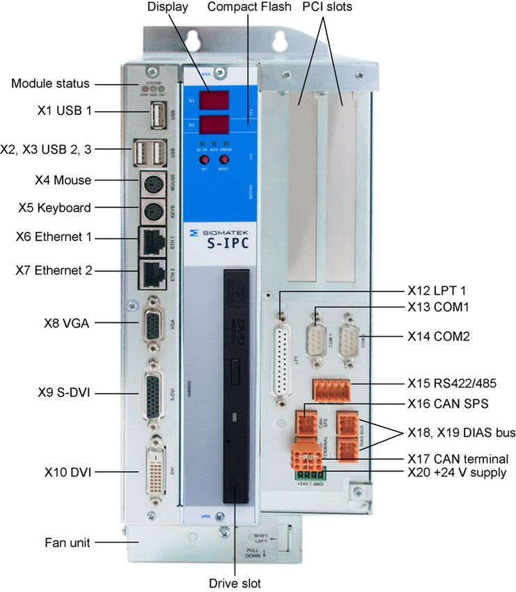
S-IPC INTEL® ATOM DUAL CORE

Contents
     Contents ..................................................................................................... 2
     Technical Data ........................................................................................... 3
     Postcodes................................................................................................... 6
     Mechanical Dimensions (with fan and heat sink) .................................. 7
     Mechanical Dimensions (with heat sink) ................................................ 8
     Mechanical Dimensions (mounts) ........................................................... 9
     Connector Layout .................................................................................... 10
        Front connectors.................................................................................... 11
        Bottom Connectors................................................................................ 17
     Status Displays ........................................................................................ 18
     Sigmatek Components............................................................................ 20
     S-IPC Status ............................................................................................. 21
     Exchanging the CompactFlash Card..................................................... 24
     Exchanging the Battery .......................................................................... 25
     Buffer Battery........................................................................................... 26
     Exchanging the Fan ................................................................................ 27
     Mounting PCI Cards ................................................................................ 28
     Exchanging the Drive unit ...................................................................... 30
     Cooling ..................................................................................................... 31
     Mounting Instructions............................................................................. 31
     Wiring Guidelines .................................................................................... 32
        1. Earth Connection............................................................................... 32
        2. Shielding............................................................................................ 33
        3. ESD Protection .................................................................................. 33
        4. DIAS Bus Termination ....................................................................... 34
        5. DIAS bus connection to C-DIAS modules......................................... 34
        6. Connecting DIAS Modules ................................................................ 35
        7. CAN Bus Termination........................................................................ 36
        8. USB Interface Connections ............................................................... 37
        9. RS485 Bus Termination .................................................................... 38
     Pictures of the S-IPC ............................................................................... 39

Page 2                                                                                                21.02.2014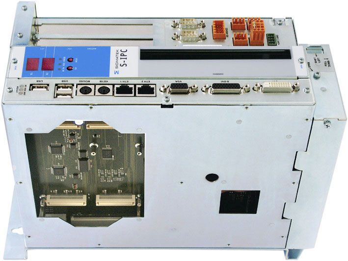
S-IPC INTEL® ATOM DUAL CORE

Technical Data
Performance data

  Processor                                  Intel® Atom D510 (1.66 GHz, Dual Core) / 1 Mbytes L2 Cache

  Internal program memory (CompactFlash)                      2x CompactFlash Type I or II

  Drive unit                                                   1 x 40 Gbytes hard drive
                                                 1 x CD-ROM / DVD-Combo drive / 40 Gbytes hard drive

  Internal program memory (SRAM)                              256 Kbytes (battery powered)

  Internal program memory (SDRAM)                                1 Gbytes DDR2 SDRAM

  Interfaces                               2 x Ethernet 10/100 Mbit
                                           1 x RS232 – COM1
                                           1 x RS232 / RS485 – COM2
                                           1 x LPT
                                           2 x PS/2 – keyboard and mouse
                                           1 x DIAS intelligent (connected over 2 pugs)
                                           1 x C-DIAS-Bus
                                           1 x CAN for PLC
                                           1x CAN for a Terminal
                                           1x S-DVI interface for a terminal (TFT display, USB, CAN key-
                                              board)
                                           1 x DVI interface for a monitor
                                           1 x VGA – analog RGB
                                           3 x USB V2.0
                                           1 x Optional connection for fan unit (2 fans, monitored)

                                           IDE devices:
                                           2 x CompactFlash
                                           1 x hard drive
                                           1 x CD-ROM / DVD-Combo / hard drive

                                           Expansion cards:
                                           2 x PCI-Bus (+5 V, half-size)

  Data buffer                                                         Lithium battery

  Status display                                                             Yes

  Status LEDs                                                                Yes

  Real-time clock                                                            Yes

21.02.2014                                                                                            Page 3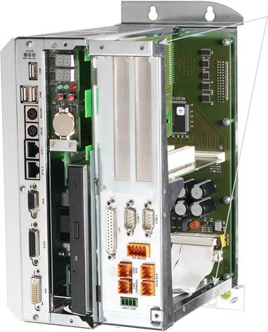
S-IPC INTEL® ATOM DUAL CORE

Electrical requirements

  Supply voltage                                                     Typically +24 V DC
                                                                     +18 V to +30 V DC

  Supply voltage current consumption                                Typically 750 mA
                                                                       Up to 5.0 A
                                                     (Depending on the PCI slots and external devices)
  Starting current                                              Maximum 10 A for 100 ms

  Available current for CAN (+5 V)                                    Maximum 1.0 A

  Available current for C-DIAS (+5 V)                                 Maximum 1.5 A

  Available current for S-DVI (+24 V)                                 Maximum 1.5 A

  Available current for PCI (+3.3 V)                                  Maximum 5.0 A

  Available current for PCI (+5 V)                                    Maximum 3.0 A

  Available current for PCI (+12 V)                                   Maximum 1.0 A

  Available current for PCI (-12 V)                                   Maximum 0.5 A

  Available current for PCI (+5 V)                                    Maximum 1.5 A

Miscellaneous

  Article connections S-IPC complete    Article          DDR-Ram          HDD Gbytes     CD-Rom /      Fan / heat
  devices:                              number           Mbytes                          DVD-Combo     sink

  S-IPC with fan:                       12-400-161        1 Gbytes            40.0       DVD-Combo         Fan

  S-IPC with heat sink:                 12-400-162        1 Gbytes            40.0       DVD-Combo       Heat sink

  Article numbers for replacement       Article number    40.0 Gbytes hard           CD-Rom            Fan +24 V
  parts:                                                  drive                      DVD-Combo

  Fan unit (2 fans):                     12-410-011                   -                    -         2 x (80x80x25)

  Drive unit (HDD):                      12-410-021                  Yes                   -               -

  Drive unit (HDD + CD):                 12-410-031                  Yes                 CD-Rom            -

  Drive unit (HDD + DVD):                12-410-041                  Yes             DVD-Combo             -

  Module identification on DIAS bus                                           No

  Hardware Version                                                            1.x

  Standard                                                                UL (E247993)

           CD Rom:    CD read
           DVD-Combo: DVD read, CD read and write

Page 4 a                                                                                              21.02.2014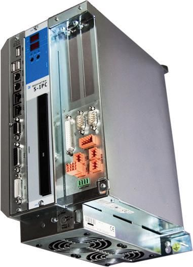
S-IPC INTEL® ATOM DUAL CORE

Environmental conditions

  Storage temperature                                       -20 – +65 °C

  Operating temperature                    S-IPC                                    S-IPC
                                 without using the PCI slots                 using the PCI slots

  Cooling with the fan unit             +5 – +55 °C                               +5 – +50 °C

  Cooling with a heat sink              +5 – +50 °C                               +5 – +45 °C

  Humidity                                            10 - 85 %, non condensing

  EMC stability                             According to EN 61000-6-2 (industrial area)

  Shock resistance                    EN 60068-2-27                                150 m/s²

  Protection Type                        EN 60529                                    IP 20

    The CAN bus terminal is initialized by the FPGA and has only limited in use!
  The FPGA reads the display configuration over the CAN bus terminal and monitors the
   keyboard. Several CAN objects of the CAN bus terminal are therefore not available.

 Le moniteur de bus CAN est initialisé par le FPGA et son domaine d'utilisation est
                                           limité.
 Le FPGA lit la configuration d'affichage via le moniteur de bus CAN et gère le clavier. En
  conséquence plusieurs objets Can du moniteur de bus CAN ne sont pas disponibles.

21.02.2014                                                                                         Page 5
S-IPC INTEL® ATOM DUAL CORE

Postcodes

When the S-IPC is turned on, the BIOS-dependent postcodes are shown in the display. It is
important to note these codes in order to simplify troubleshooting if the S-IPC does not boot
                                             up.

 Lorsque le S-IPC est sous tension, les BIOS power-on self-test codes sont affichés à l'é-
cran. Il est important de noter ces codes afin de rendre le dépannage plus facile si le S-IPC
                                       ne démarre pas.

Important Postcodes:

C3: Memory could not be initialized – DDR RAM defective

FF: Boot process started

If the reset button is pressed, the first line shows the FPGA identification ("0A") and the
second line, the FBGA version (e.g.: "10").

Page 6                                                                              21.02.2014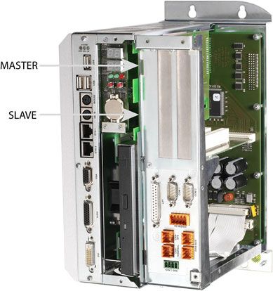
S-IPC INTEL® ATOM DUAL CORE

Mechanical Dimensions (with fan and heat sink)

21.02.2014                                               Page 7
S-IPC INTEL® ATOM DUAL CORE

Mechanical Dimensions (with heat sink)

Page 8                                   21.02.2014
S-IPC INTEL® ATOM DUAL CORE

Mechanical Dimensions (mounts)

                                    Earth terminal

21.02.2014                                           Page 9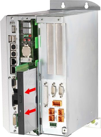
S-IPC INTEL® ATOM DUAL CORE

Connector Layout

Page 10                       21.02.2014
S-IPC INTEL® ATOM DUAL CORE

Front connectors

X1 – 3: USB 1 – 3 (Type A)

                                PIN              Function
                                 1                 +5 V
                                 2                 D0-
                                 3                 D0+
                                 4                 GND

X4: PS2 mouse

                               PIN              Function
                                1             MOUSE DATA
                               2, 6             Not used
                                3                 GND
                                4                 +5 V
                                5             MOUSE CLOCK

X5: PS2 keyboard

                               PIN               Function
                                1             KEYBOARD DATA
                                2              MOUSE DATA
                                3                  GND
                                4                  +5 V
                                5            KEYBOARD CLOCK
                                6              MOUSE CLOCK

The PS2 keyboard connection can be used for a keyboard and mouse with a "Y cable". The
               PS2 mouse connector (X4) in this case, cannot be used!

21.02.2014                                                                   Page 11
S-IPC INTEL® ATOM DUAL CORE
X6, 7: Ethernet 1, 2 (8-pin RJ45)
PIN Function
1 TD+
2 TD–
3 RD+
4 Not used
5 Not used
6 RD–
7 Not used
8 1 8 Not used
X8: VGA output (15-pin HD-DSUB)
PIN Function
1 Red
2 Green
3 Blue
4 Nicht belegt
5 GND
6 Red GND
7 Green GND
8 Blue GND
9 +5 V
10 GND
11 Nicht belegt
12 DDC DAT
13 H-Sync
14 V-Sync
15 DDC CLK
Page 12 21.02.2014S-IPC INTEL® ATOM DUAL CORE
X9: S-DVI (26-pin HD-DSUB)
1 PIN Function PIN Function
1 DVI1+ 14 GND
2 DVI1- 15 GND
3 DVI2+ 16 GND
4 DVI2- 17 GND
5 DVI3+ 18 GND
6 DVI3- 19 +24 V
7 DVIC+ 20 +24 V
8 DVIC- 21 USB Ext. In+
9 Reserved 22 USB Ext. In-
10 GND 23 USB Ext.
Out+
11 GND 24 USB Ext.
Out-
12 GND 25 CAN A
13 GND 26 CAN B
X9 cannot be connected while voltage is applied!
The +24 V supply must be turned off.
X9 ne doit pas être inséré sous tension!
L'alimentation 24 V doit être éteinte.
X10: DVI (24-pin DVI without analog RGB)
PIN Function PIN Function
1 DVI2- 13 DVI3+
2 DVI2+ 14 +5 V
3 GND 15 GND
4 DVI4- 16 Hot Plug Detect
5 DVI4+ 17 DVI0-
6 DDC-CLOCK 18 DVI0+
7 DDC-DATA 19 GND
8 V-Sync *) 20 DVI5-
9 DVI1- 21 DVI5+
10 DVI1+ 22 GND
11 GND 23 DVI-CLOCK+
12 DVI3- 24 DVI-CLOCK-
C1 Red *) C4 H-Sync *)
C2 Green *) C5 GND *)
C3 Blue *)
*)
Analog RGB is not wired into the socket (not used)
The following resolutions are supported:
640x480 – 18-bit color depth
800x600 – 18-bit color depth
1024x768 – 18-Bit color depth
21.02.2014 Page 13S-IPC INTEL® ATOM DUAL CORE
X11: Fan unit connection (4-pin Phoenix RM3.81)
PIN Function
1 VCC-FAN
2 Monitor 1
3 Monitor 2
4 GND
1
If the fan unit available from Sigmatek (article number: 12-410-011) is not used, a conven-
tional +24 V fan with a maximum current consumption of 250 mA can be connected!
X12: LPT 1 (25-pin DSUB)
PIN Function
1 \STB
2 PD0
3 PD1
4 PD2
5 PD3
6 PD4
7 PD5
8 PD6
9 PD7
10 \ACK
11 BUSY
12 PE
13 SLCT
14 \AFD
15 ERR
16 \PINIT
17 SLIN
18 – 25 GND
X13, 14: COM 1, COM 2 – RS232 (9-pin DSUB)
1 5
PIN Function
1 DCD
2 RXD
3 TXD
6 9 4 DTR
5 GND
6 DSR
7 RTS
8 CTS
9 RI
Page 14 21.02.2014S-IPC INTEL® ATOM DUAL CORE
X15: COM 2 – RS485/422 (10-pin Weidmüller plug)
1 2
PIN RS422 *) RS485
1 RS422 TxD+ RS485 A
2 RS422 TxD- RS485 B
3 RS422 RxD+ RS485 A
4 RS422 RxD- RS485 B
5 +5 V +5 V
6 GND GND
7 RS422 TxD+ RS485 A
8 RS422 TxD- RS485 B
9 RS422 RxD+ RS485 A
10 RS422 RxD- RS485 B
9 10
*) Currently not connected
X16: CAN bus PLC (6-pin Weidmüller plug)
12
PIN Function
1 CAN SA = LOW
2 CAN SB = HIGH
3 CAN SA = LOW
4 CAN SB = HIGH
5 GND
6 +5 V (for online adapter)
56
X17: CAN bus terminal (6-pin Weidmüller plug)
12 PIN Function
1 CAN A = LOW
2 CAN B = HIGH
3 CAN A = LOW
4 CAN B = HIGH
5 GND
6 Not used
56
21.02.2014 Page 15S-IPC INTEL® ATOM DUAL CORE
X18, 19: DIAS bus (6-pin Weidmüller plug)
12
PIN Function
1 MBUS+
2 MBUS-
3 SBUS+
4 SBUS-
5 GND
6 Not used
56
X20: Power supply (4-pin Phoenix RM3.5)
PIN Function
1 +24 V
2 +24 V
1 3 GND
4 GND
Applicable connectors
USB: Type A
Ethernet: 8-pin RJ45
VGA: 15-pin HD-DSUB plug
S-DVI: 26-pin HD-DSUB plug
DVI: 24-pin DVI plug
Fan: 4-pin Phoenix FK-MCP 1.5/4-ST-3.81
LPT 1: 25-pin DSUB plug
COM 1 / COM 2: 9-pin DSUB socket
COM 2 – RS422/485: 10-pin Weidmüller plug B2L 3.5/10
CAN- / DIAS-Bus: 6-pin Weidmüller pin B2L 3.5/6
Power supply: 4-pin Phoenix FK-MCP 1.5/4-ST-3.5
The complete C-DIAS CKL 015 connector set with spring terminals is available from SIG-
MATEK under the article number 12-600-015.
S-DVI Cable 0.3 m Art.Nr.: 05-950-003
2m Art.Nr.: 05-950-020
3m Art.Nr.: 05-950-030
5m Art.Nr.: 05-950-050
10 m Art.Nr.: 05-950-100
15 m Art.Nr.: 05-950-150
Page 16 21.02.2014S-IPC INTEL® ATOM DUAL CORE
Bottom Connectors
X21: C-DIAS Bus Connector
16 1
c
b
a
The S-IPC can be mounted on the left of a CMB.
21.02.2014 Page 17S-IPC INTEL® ATOM DUAL CORE Status Displays LED 1 Green DC OK Lights when the supply voltage is correct. LED 2 Green RUN Lights when the program is running LED 3 Red ERROR Lights when a program error occurs. Button 1 Set Set/display Ethernet, CAN address, power on. Button 2 Reset Reset CPU hardware Page 18 21.02.2014
S-IPC INTEL® ATOM DUAL CORE

  LED 1       Red     ERR   1.00 s on/off: EEProm error
                            0.50 s on/off: temperature sensor – over temperature
                            0.25 s off/on: fan error
                            0.10 s off/on: battery – over temperature
  LED 2      Yellow   HDD   Lights when the hard drive is accessed.
  LED 3      Green    On    Lights when the ETX board is turned on.

21.02.2014                                                                         Page 19
S-IPC INTEL® ATOM DUAL CORE
Sigmatek Components
• 7-segment display for CPU status
• Reset button
• Set button
• DC OK LED
• Error LED
• Run LED
• Timer - 1 µs precision with Interrupt capability
• EEPROM for configuration and version management
• S-DVI interface including:
Keyboard
- USB
- Touch
- Chip card
- PC speakers
- 18-Bit TFT signal TMDS coded (3x data, 1x clk), max. resolution 1600x1200
Page 20 21.02.2014S-IPC INTEL® ATOM DUAL CORE
S-IPC Status
o When installing the Sigmatek driver, a "Sigmatek" program group is created that
contains the "SipcInfo" program.
o The program and driver version, as well as several hardware parameters are dis-
played:
o Restart counter
o ETX and CPU temperature
o S-IPC and fan operating hours counter
o Fan speed (revolutions/second)
o Fan PWM stage (preset speed in 16 stages)
21.02.2014 Page 21S-IPC INTEL® ATOM DUAL CORE
o With a cooling defect (fan defective, ambient temperature too high), as well as a
critical error, an error message is generated by the S-IPC: T
o Cancel error messages:
o The alarm can be delayed for any amount of time by entering the desired
value in the "Suppress alarms for the next [] seconds" field.
o Set alarm parameters:
o The PWM stage ("Desired Fan Speed") can be set between 0 and 15,
and indicates the fan speed from 0% to 100%.
o Starting from a PWM stage of (default value) 10, the fan speed is ana-
lyzed and an alarm message generated when one or both fans malfunc-
tion.
o With the
"HKEY_LOCAL_MACHINE\SYSTEM\CurrentControlSet\Services\SIPC\
Parameters\FanBlockedDetectionThreshold" registry key
the fan speed monitor can be defined:
Values < 5 are impractical, since the fan typically starts with
PWM stage of 2 .. 3.
A value > 15 means that no fan warning is generated, since the
highest PWM stage is 15.
The default value after the drive installation is 10.
o Activate and deactivate alarms:
With the deactivation of alarms, the application must assume (thermal) monitoring to
avoid damage to the module!
Si les alarmes sont désactivées alors l'application doit prendre en charge la surveil-
lance afin d'éviter des dommages (thermique) de l'appareil!
Page 22 21.02.2014S-IPC INTEL® ATOM DUAL CORE
o With the help from the "net stop sipclaunch" command, the alarm mes-
sages are deactivated until the next restart ("Start" – "execute" or the se-
lect input requirement). The service is thereby ended.
o With „net start sipclaunch“ the service and therewith the alarm messages
are reactivated
o With the
"HKEY_LOCAL_MACHINE\SYSTEM\CurrentControlSet\Services\
SipcLaunch\Start" registry key
the alarm service can be deactivated :
A value of 2 (= SERVICE_AUTO_START) means that the ser-
vice is started while booting and alarm messages are generated.
A value of 3 (= SERVICE_DEMAND_START) means that the
service is not automatically starting during boot-up and therefore
no alarm messages are generated.
21.02.2014 Page 23S-IPC INTEL® ATOM DUAL CORE
Exchanging the CompactFlash Card
To exchange the CompactFlash
cards, the 2 mounting screws for the
7-segmatek display / drive unit must
be removed.
The cover can then be removed by
pulling it straight forward.
Locking
Screws
The master CompactFlash and the
slave can now be exchanged.
Next replace the cover and locking
screws.
A CompactFlash card cannot be exchanged while voltage is applied to the unit!
Because the CompactFlash cards are used as an IDE device, it cannot be exchanged dur-
ing operation!
Page 24 21.02.2014S-IPC INTEL® ATOM DUAL CORE
Une carte CompactFlash ne peut être échangée tandis que la tension est présente!
Vu que la carte Compact Flash est utilisée comme un module d'IDE, on ne peut pas l'é-
changer pendant que le système est en marche.
Exchanging the Battery
To exchange the buffer battery, the 2
mounting screws for the 7-segmatek
display / drive unit must be removed.
The cover can then be removed by
pulling it straight forward.
Locking
Screws
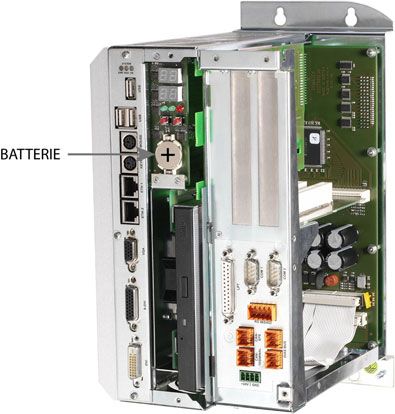
The battery is not removed (lift on the
right side) and a new battery inserted.
Next replace the cover and locking
screws.
21.02.2014 Page 25S-IPC INTEL® ATOM DUAL CORE
The battery should only be exchanged when the S-IPC is off.
The battery must be installed with the + POLE forward. The + POLE is visible on the battery
when installed, the smaller – POLE is below in the battery socket.
CAUTION:
The battery can only be changed when the IPC is off! After the +24 V supply is removed,
the battery is buffered for approximately 5 minutes (via ELKO). The battery must be
changed within this period or data loss occurs.
ATTENTION:
La pile ne doit être changée que si le S-IPC est éteint! Après avoir débranché l'alimentation
+24 V, la pile est tamponnée pendant 5 minutes (via ELKO). La pile doit être remplacée
pendant ce laps de temps sinon les données seront perdues.
Buffer Battery
The exchangeable buffer battery ensures that programs and data in the user memory
(RAM) are preserved in the absence of a supply voltage. A lithium battery is installed at the
manufacturer.
The battery has enough capacity to preserve data in the absence of a supply voltage for up
to 3 years.
We recommend however, that the battery be replaced annually to ensure optimal perform-
ance.
Battery order number: 01-690-028
MANUFACTURER TYPE DATA
Lithium battery RENATA CR2032 3V
Use only batteries from RENATA with the number CR2032! With any other batter the
danger of fire or explosion exists!
N'utilisez que des piles RENATA CR2032! Avec d'autres piles, un risque d'incendie
ou d'explosion existe!
Page 26 21.02.2014S-IPC INTEL® ATOM DUAL CORE
Exchanging the Fan
The fan can be exchanged at any time
(also during operation). To exchange the
fan, the M3 screw on the fan unit must be
removed.
Next, the lock must be moved to the left
and the fan unit can be removed down-
ward.
When using the fan unit, first hang the fan
unit on the back and the push straight up-
ward to secure it. The lock is on the left.
The lock is then moved to the right and the
M3 screw reinserted.
Instead of the fan unit, a conventional 80x80x25 mm +24 V fan can also be used. See the
connector layout!
Les ventilateurs +24 V 80x80x25 mm disponibles dans le commerce peuvent également
être utilisés à la place de l'unité de ventilation. Voir la connectique.
Should one of the two fans fail, the software shows the status (+ status LED). In this case,
the S-IPC can continue to operate with only one fan until the defective fan unit is replace.
Under some conditions, the maximum ambient temperature cannot be reached by the time
the fan unit is replace.
Si l'un des deux ventilateurs tombe en panne, le défaut est signalé dans le logiciel ainsi que
par une LED. Dans ce cas, le S-IPC peut fonctionner avec un seul ventilateur jusqu'à ce
que le ventilateur soit remplacé. Selon les conditions, la température maximale de l'envi-
ronnement ne peut pas être atteinte avant le ventilateur est échangé
21.02.2014 Page 27S-IPC INTEL® ATOM DUAL CORE
Mounting PCI Cards
To open the side panel, 3 mounting screws
must be removed.
Afterwards, the side panel can be lifted and
removed upward.
Page 28 21.02.2014S-IPC INTEL® ATOM DUAL CORE
When remounting the side panel, ensure
that the locking mechanism engages cor-
rectly.
To install the PCI card, the slot bracket
must first be removed (1x M3 screw). The
mounting screws are used to secure the
PCI cards.
A PCI card can only be installed when no voltage is applied (+24 V supply discon-
nected)!
Une carte PCI ne peut pas être installée tant que la tension est présente (alimentation
+24 V deconnecté)!
21.02.2014 Page 29S-IPC INTEL® ATOM DUAL CORE
Exchanging the Drive unit
The two mounting screws on the 7-
segment display/drive unit and the
cover must first be removed.
Locking
Screws
The drive unit can then be removed
from the front using the grip.
After inserting the new drive unit, the
cover is remounted wit the two mount-
ing screws.
A drive unit can only be exchanged when no voltage is applied (+24 V supply dis-
connected)!
Page 30 21.02.2014S-IPC INTEL® ATOM DUAL CORE
Le lecteur DVD ne peut être modifié que si le S-IPC est éteint (alimentation +24 V
déconnecté)!
Cooling
The S-IPCs power loss can reach up to 100 Watts. Most of the generated heat is removed
by the built in fan or the heat sink. Also when mounted, heat dissipation must be ensured.
A clearance of 10 cm around the S-IPC is strongly recommended. This ensures that the
waste heat can be dissipated.
At processor temperatures above the allowed limit, the S-IPC will shut down auto-
matically!
Le S-IPC s'arrête automatiquement en présence d’une température trop élevée du
processeur!
Mounting Instructions
The S-IPC has 4 mounting holes for mounting on the back wall of the control cabinet.
This is the preferred mounting position, since the cool air can flow from the bottom (fan unit)
to the top of the module and ensure optimal cooling.
A different mounting position is not recommended; the specified ambient temperature
thereby cannot be reached.
In addition, a clearance of 10 cm between the nearest components (control cabinet wall)
must be ensured.
The left housing wall (heat sink) can be very hot and can lead to injury, especially at
high ambient temperatures!
Le panneau de logement à gauche (dissipateur thermique) peut devenir extrêmement
chaud et est dangereux, surtout à des températures élevées!
21.02.2014 Page 31S-IPC INTEL® ATOM DUAL CORE
Wiring Guidelines
1. Earth Connection
The S-IPC must be connected to earth through the mounting on control cabinet or over the
earth terminal provided. It is important to create a low-ohm earth connection, only then can
error-free operation be guaranteed. The earth connection should have the maximum cross
section and the largest electrical surface possible.
Any noise signals that reach the S-IPC over external cables must be dissipated over the
earth connection. With a large electrical surface, high frequency noise can also be dissi-
pated (skin effect).
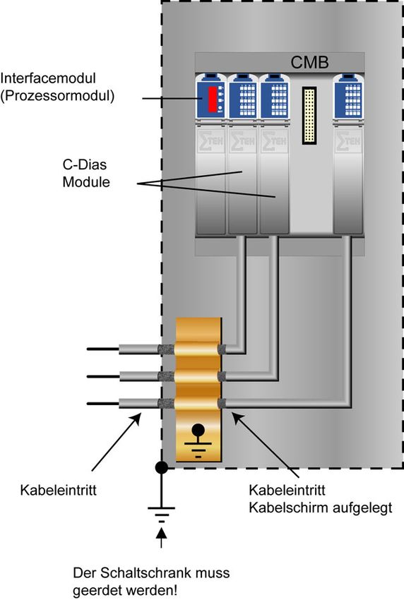
Interface module
(Processor module)
C-DIAS
Modules
Cable entrance Cable entrance
Cable shielding connected
The control box must
be connected to earth!
Page 32 21.02.2014S-IPC INTEL® ATOM DUAL CORE 2. Shielding The wiring for theCOM1, COM2, RS485, CAN-Bus, DIAS-Bus, VGA, S-DVI and DVI must be shielded. For RS485, CAN bus and DIAS bus, twisted pair wires must also be used. The prefabricated S-DVI cable is available from Sigmatek in various lengths. The low-ohm shielding is either connected at the entry to the control cabinet or directly before the S-IPC of a large surface (cable grommets, grounding clamps)! Noise therefore cannot reach the electronics and affect the function. 3. ESD Protection Typically, the PS/2 devices (keyboard, mouse) are not equipped with shielded cables. The same is true for a USB keyboards and mouse; these devices are disrupted by ESD and in some instances, no longer function. Before any device is connected to or disconnected from the S-IPC, the potential with ground should be equalized (by touching the control cabinet or earth terminal). Electrostatic loads (through clothing and shoes) can thereby be dissipated. 21.02.2014 Page 33
S-IPC INTEL® ATOM DUAL CORE

4. DIAS Bus Termination

In a DIAS bus system, both end modules must be terminated. This is required to avoid data
transfer errors that are caused by reflections in the data lines.

If the S-IPC is one to the end modules, the termination can be made with a 100-Ohm resis-
tor between MBUS+ and MBUS as well as SBUS+ und SBUS-. If this is the case, the 2nd
DIAS bus connector is for the remains available.

      2 x 100-Ohm resistor

5. DIAS bus connection to C-DIAS modules

To ensure a good bus connection, several wiring guidelines must be followed:

 •   The cable used must be designed for the data transfer speed:
              Data cable (10 MBits, 2 x 2 wire TWISTED PAIR, shielded)
              E.g.: LAPPKABEL / UNITRONIC-BUSLEITUNG FD P LD
 •   Because of the internal resistance of the module, the cable impedance should be 100
     Ohms.
 •   With twisted-pair cables, ensure that the correct pairs are connected to one another:
                 2x2 pair cables:    Pair 1      MBUS+
                                                 MBUS-
                                     Pair 2      SBUS+
                                                 SBUS-
 •   The shielding must be connected over a large area and the shortest possible route.
 •   To connect the individual wires to the connector, the insulation must be removed and
     the exposed shielding shifted to the side. Only remove as much of the insulation and
     shielding as needed.

Page 34                                                                        21.02.2014
S-IPC INTEL® ATOM DUAL CORE
• The send and receive modules must have the same GND potential.
The maximum length allowed for twisted-pair cables 20 m (when using the UNI-
TRONIC bus cable FD P LD / LAPPKABEL)
La longueur maximale totale d'un câble à paire torsadée est de 20 m (lors de l'utilisa-
tion UNITRONIC BUS FD P LD / Fa. LAPPKABEL)
I.e CCP 901
I.e CCP 901
2 x 2 wire Twisted-Pair Cable
The distance between a and b should be kept as short as possible!
The shielding should be connected to GND over the shortest route
possible!
6. Connecting DIAS Modules
The C-IPC can also be connected to a DIAS module.
However, the DIAS modules require a power supply (a DPS 001, for example) as well as an
adapter module for connect the twisted-pair cable to the ribbon cable connector (e.g.: DKO
012 /013).
6.1 Connection over a DIC 121
The DIAS bus connection between the S-IPC and DIC 121 is a point-to-point con-
nection and must therefore be terminated on both sides. The DIC 121 has an inte-
grated bus termination
Wiring the S-IPC:
o X18: Install bus termination (2x 100 Ω)
o X19: Connect to DIC 121
21.02.2014 Page 35S-IPC INTEL® ATOM DUAL CORE
6.2 Connection over a DKO 011or DKO 013:
If both DIAS bus connections to the S-IPC are needed, a DKO 011 or DKO 013 can be
used in combination with a DPS 001 power supply module.
Wiring the DIAS modules with a DPS 001:
o Left: DPS 001 power supply module
o Right: DKO 011 or DKO 013 adapter module
Wiring the S-IPC:
o X18: DIAS bus to CIC interface modules or bus termination (2 x 100 Ω)
o X19: Connection to DKO 011 or DKO 013 adapter module
7. CAN Bus Termination
In a CAN bus system, both end modules must be terminated. This is necessary to avoid
transmission errors caused by reflections in the line.
Module 1 Module 2 Module 3 Module n
I.e. CPU I.e. Terminal I.e. Terminal
DCP 160 ET 081 ET 805
CAN Bus DSUB plug
Termination on with termination
terminal module circuit
CAN Bus connection
If the S-IPC is an end module, it can be terminated by placing a 150-Ohm resistor between
CAN-A (LOW) and CAN-B (HIGH).
The bus termination on the CAN terminal is installed before delivery!
1 x 150-Ohm resistor
Page 36 21.02.2014S-IPC INTEL® ATOM DUAL CORE
8. USB Interface Connections
The S-IPC has a USB interface connection that can be used in LASAL to connect various
USB devices (keyboard, mouse, storage media, Hubs …). Several USB devices, which are
fully functional in LASAL, can be connected using a hub.
The following restriction applies to the BIOS setup:
The BIOS setup can only be operated when the USB keyboard is connected directly to the
USB socket. Using a USB hub can cause errors in the BIOS setup!
La configuration du BIOS est accessible uniquement si le clavier est connecté directement
à la prise USB. L'utilisation d'un concentrateur USB peut provoquer des erreurs dans la
configuration du BIOS!
It should be noted that many of the USB devices on the market do not comply with USB
specifications; this can lead to device malfunctions. It is also possible that these devices will
not be detected at the USB port or function correctly. Therefore, it is recommended that
every USB stick be tested before actual use.
Il faut souligner que la plupart des périphériques USB sur le marché ne sont pas conformes
aux spécifications USB, ce qui peut entraîner des dysfonctionnements de l'appareil. Il est
également possible que ces dispositifs ne seront pas détectés par le port USB ou qu’ils ne
fonctionnent pas correctement. Par conséquent, il est recommandé que chaque clé USB
soit testée avant l'utilisation sur l’automate.
21.02.2014 Page 37S-IPC INTEL® ATOM DUAL CORE
9. RS485 Bus Termination
The RS485 wired as a continuous line and connected to each bus end to avoid reflections.
Here, there are 2 termination types:
o Bus termination with quiescent level definition:
o Both 330 – 390 Ω resistors ensure a defined bus status when all participants are
passive (receive). Wiring:
-A +5 V
-B GND
o Bus termination:
Page 38 21.02.2014S-IPC INTEL® ATOM DUAL CORE
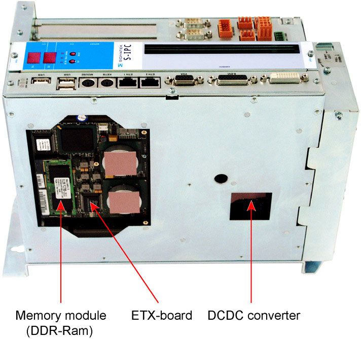
Pictures of the S-IPC
The ETX board can be accessed by removing the heat sink. This may be necessary to
exchange the memory (DDR Ram). When assembling the S-IPC, caution must be taken to
ensure that no contamination gets between the GAP pads (here: pink) and the heat sink!
On peut accéder à la carte ETX une fois le dissipateur de chaleur retiré. Cela peut être
nécessaire dans le but d'échanger la mémoire (RAM DDR). Lors du réassemblage du S-
IPC, on doit veiller à ce qu'aucune saleté ne s’est infiltrée entre les tampons gap (ici, rose)
et le dissipateur de chaleur!
21.02.2014 Page 39S-IPC INTEL® ATOM DUAL CORE
View without ETX board
Page 40 21.02.2014S-IPC INTEL® ATOM DUAL CORE
S-IPC with heat sink and fan
At extreme ambient temperatures (high ambient temperature, continuous high processor
load), a fan unit should be mounted onto an S-IPC with a heat sink to extend the life of the
CD Rom/DVD and hard drive!
Dans des conditions environnementales extrêmes (températures élevées, charge élevée du
processeur sur une durée), une unité de ventilateur doit être monté sur le S-IPC en plus du
dissipateur de chaleur afin d'augmenter la durée de vie du lecteur CD-Rom / DVD et des
disques durs.
21.02.2014 Page 41S-IPC INTEL® ATOM DUAL CORE Page 42 21.02.2014
You can also read