Scattering symmetry breaking induced spin photocurrent from out of plane spin texture in a 3D topological insulator - Nature
←
→
Page content transcription
If your browser does not render page correctly, please read the page content below
www.nature.com/scientificreports
OPEN Scattering symmetry‑breaking
induced spin photocurrent
from out‑of‑plane spin texture
in a 3D topological insulator
Y. Q. Huang*, I. A. Buyanova & W. M. Chen
We theoretically study helicity-dependent photocurrent in a three-dimensional topological insulator
Bi2Te3 under elastic scattering of different symmetries. By exploring spin-selective optical transitions
and symmetry-breaking scattering, we are able to address the out-of-plane spin texture of the
topological helical surface states and to generate directional, spin-polarization tunable photocurrent
that is otherwise forbidden for the original C3v symmetry of the surface. This can be achieved
regardless of the Fermi level, even under the condition when the topological states are inaccessible in
dark. This work paves the way to robustly explore the out-of-plane spin texture for harvesting opto-
spintronic functionalities of topological insulators.
A three-dimensional (3D) topological insulator (TI), for instance B i2Te3, has an insulating bulk and a metallic
surface that is characterized by the topological surface states (TSSs)1–9. Owing to the strong spin–orbit inter-
action, the spin of the TSS is locked to its momentum such that efficient electron spin polarization as well as
non-equilibrium spin current can be generated electrically, making it attractive for dissipationless spintronic
and quantum information applications10–18. Recently, an alternative method is discovered through which spin-
polarized current can be efficiently created in 3D TIs by circularly polarized light excitation19–25. This so-called
circular photogalvanic effect allows for a non-equilibrium flow of spin current and exhibits large tolerance against
doping conditions of the materials19,26–28. The high efficiency and flexibility of the method not only suggest great
advantage for studying spin generation, manipulation and transport in TIs, but also open a new gateway for
future opto-spintronics.
The early studies on spin and non-equilibrium spin current generation in 3D TI have focused on the spin
component that is parallel to the surface of the 3D TI. In materials like B i2Te3, however, a strong hexagonal
warping effect also leads to a pronounced out-of-plane spin texture of the TSS that rises up to the strength of
its in-plane counterpart and progressively increases with the energy of the TSS moving away from the Dirac
point. In this work, we theoretically investigate the generation of spin polarization and non-equilibrium spin
current through such out-of-plane spin texture by exploring the symmetry-breaking effect induced by scatter-
ing. We show that elastic scattering of the TSS via line defects breaks the C3v symmetry of the Bi2Te3 surface and
consequently gives rise to a new photocurrent component, of which the magnitude and spin polarization can
be tuned by changing the Fermi energy.
The device structure and measurement geometry used in this work is defined in Fig. 1(a). We consider a
(111)-grown
− Bi2Te3 thin film made of 30 quintuple layers (QLs). The x- and z-axis are chosen to lie along the
[ 1 10] and [111] axes of the film, respectively. The device is illuminated with single-color circularly polarized light
propagating in the x–z plane with an incidence angle θ . The resulting photocurrent density under the σ + or σ −
polarized excitation, jσ ±, is decomposed into components along the x and y directions, marked by the yellow
arrows in Fig. 1(a). The helicity-dependent photocurrent (HPC) density jpol is the photocurrent density difference
taken between the two opposite excitation helicities. The tight-binding description of the electronic structure
of the Bi2Te3 thin film is adopted from Ref.29 by considering the Bi2Te3 thin film as stacking of N number of lay-
ers of Bi and Te atoms which are arranged in a 2D hexagonal lattice in the x–y plane. The preserved translation
Department of Physics, Chemistry and Biology, Linköping University, 581 83 Linköping, Sweden. *email: yuqing.
huang@liu.se
Scientific Reports | (2020) 10:10610 | https://doi.org/10.1038/s41598-020-67612-3 1
Vol.:(0123456789)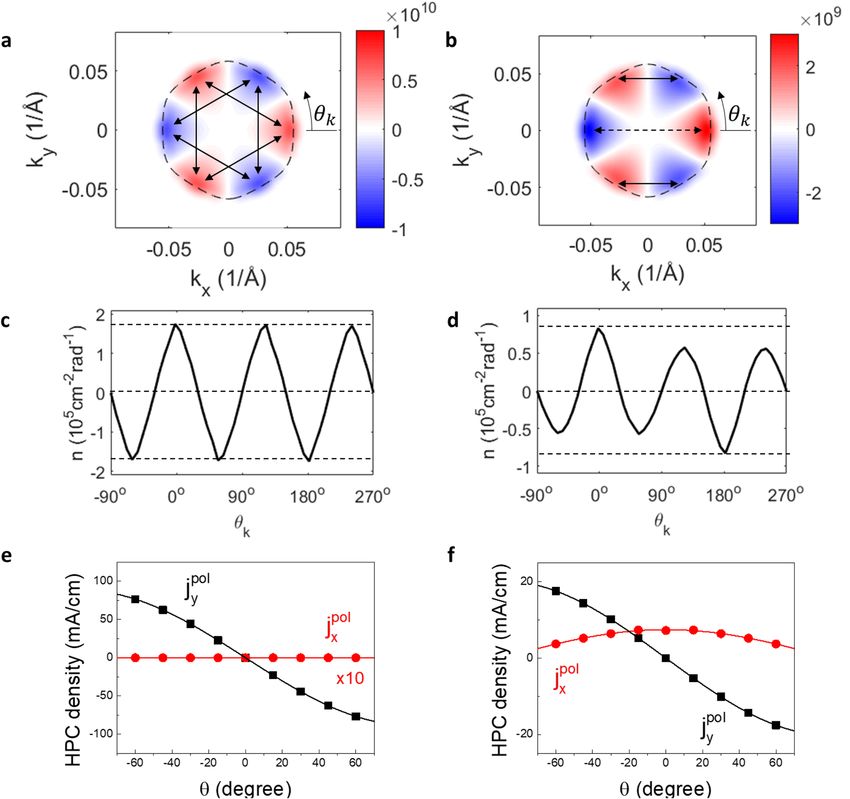
www.nature.com/scientificreports/
Figure 1. HPC component and spin-selective optical transitions. (a) The device structure used in the
calculations. The projected 2D Brillouin zone is also shown with respect to the measurement frame. (b) The
pol pol
calculated jx and jy as a function of the incidence angle θ of the excitation light as defined in (a). The EF
is set to be at 192 meV above the Dirac point and the excitation photon energy is at 1.25 eV. (c) The helicity-
dependent steady-state
◦
photocarrier distribution n(k)
◦
for the upper brunch of the Dirac cone, calculated for the
grazing (θ = 90 , upper panel) and normal (θ = 0 , lower panel) incidence. The Fermi circle is marked by the
dashed line in each case.
symmetry in the x–y plane gives rise to the projected 2D Brillouin zone as shown in Fig. 1(a). Only one equivalent
atom needs to be considered for each layer. Along the z direction, the equivalent atoms are arranged with the
repeating unit of Te2–Bi–Te1–Bi–Te2, known as the quintuple layer (QL) shown in Supplementary Fig. S1(a).
By considering this “chain” of atoms, one can write down the Hamiltonian for the (111)-grown Bi2Te3 thin film
with an arbitrary number of atomic layers and different termination atoms,
( i i′ ) c † c ′ ′ +
′ ik· r −r †
H0 = tiiαα
′ e iασ | i L · S|iα ′ σ ′ ciασ ciα′ σ ′
iασ i α σ (1)
ii′ ,αα ′ ,σ i,αα ′ ,σ σ ′
′
′
′
Here, i i labels the atom sites. α α and σ σ represent the atomic orbitals s, px , py , pz and spin quantum
†
number, respectively. ciασ (ciασ ) is the electron creation (annihilation) operator, which creates (destroys) the
electron with spin of σ and atomic orbital of′ α at site i . i is the spin–orbit strength at site i . The first term in
Eq. (1) includes ′
the on-site self-energy (i = i ) and the hopping energy′ between the nearest/second/third′ neigh-
bor site′ (i = i ), which is parameterized by the overlap integral t αα ′ between the α orbital at site i and α orbital
ii
at site i . The second term is the on-site spin–orbit interaction, which is the key ingredient for TSS formation and
the driven force of CPGE in TI.
The electronic band structure of the Bi2Te3 thin film can be obtained after diagonalizing the above Ham-
iltonian. The results are shown in Supplementary Fig.S1(b) with the tight-binding parameter from Ref.29. The
dispersion relation quantitatively reproduces the previous results from the angular resolved photoemission
spectroscopy (ARPES) and various theoretical r eports30–33. The TSS is automatically obtained, evident from the
appearing of the Dirac cone in the bulk bandgap.
The photocurrent jσ ± is determined by the steady-state density matrix ρ σ ± of TSS as jσ ± = −eTr ρ σ ± v ,
1
where v = ℏ ∇k H0 is the velocity operator with H0 being the tight-binding Hamiltonian. ρ is obtained from
σ ±
the steady-state solution of the dynamic equation of the form:
dρ σ ± 1
H0 , ρ σ ± + Gσ ± − γ rlx ρ σ ± − ρ (0) (2)
=
dt iℏ
With the basis that diagonalizes H0, we constrain the calculations only to the diagonal term of ρ σ ±. By doing
so, we ignore excitation of superposition states of TSS, which is reasonable for the TSS states with a fast decoher-
ent process. The second term generates carriers in the Dirac cone following the spin selective optical transitions
between TSS |k� and bulk state |n, k�:
1
2
Gkσ ± = 2 �n, k| − eA± · v|k�
δ Ek − En,k − ℏω 1 − ρ (0) − δ En,k − Ek − ℏω ρ (0) (3)
ℏ n
Scientific Reports | (2020) 10:10610 | https://doi.org/10.1038/s41598-020-67612-3 2
Vol:.(1234567890)
www.nature.com/scientificreports/
The summation runs through all the bulk states with the same k . A± is the Fourier transformed vector poten-
tial. ρ (0) ≡ �(EF − Ek )δk,k′ describes the equilibrium distribution at 0 K, in which �(x) is the step function, EF
δ ′
and Ek are the Fermi energy and eigen energy of the TSS, respectively. The last term in Eq. (2), γ rlx ≡ Tkk1 ,
describes the relaxation of the photogenerated carriers within the TSS. The carrier decay rate,
T1−1 = τ1−1 + τ2−1 · Ek −EF , includes energy independent and dependent contributions that describe
Ek −EF
−
kB Teff
kB Teff e +1
dT
the recombination and thermalization process34,35. Here, τ2 ≡ T1eff dteff defines the rate of thermalization process.
We noted that Gkσ ± is essential the driving term of the kinetic equation, which is balanced by the relaxation terms
and leads to the steady-state density matrix. In the presentation of TSS |k�, Gkσ ± only contains diagonal contribu-
tion. This is the result of first-order perturbation theory by considering weak optical e xcitation36. Immediately
following this simplification, the relaxation terms only need to include diagonal contribution which is represented
by γ rlx , whereas the off-diagonal inter-band transition contribution is out of scope of current w ork37. However,
we do noted that in the presence of strong excitation where higher order perturbation is need, such effect will
need to be in place.
pol pol
In Fig. 1(b), we calculate jx and jy as a function of θ . The excitation photon energy is fixed at 1.25 eV with
60-meV broadening and the relaxation parameter τ1 = 25ps . kB Teff = 4meV is chosen to represent the ther-
malization process observed in the angular resolved photoemission spectroscopy (ARPES) e xperiments35. The
EF is fixed at 192 meV above the Dirac point. We note that the TSSs involved in ρ σ ± are selected from the top
surface of the film with the sampled k-point mesh as described in Supplementary Note 1. The exclusion of the
contribution from the bottom TSSs breaks the inversion symmetry, which is a necessary condition to observe
any HPC. This also qualitatively simulates the experimental condition: the incidence light is predominantly
absorbed or reflected at the top surface ◦of the films. The calculated results represent the typical experimental
pol
observation that a tilted excitation ◦
(θ = 0 ) creates an HPC propagating perpendicular to the incidence plane ( jy
in our configuration). For θ = 0 , no HPC is detected along either x or y directions. In the symmetry argument
put forward by McIver et.al., the C3v symmetry of the B i2Te3 surface forbids HPC under the normal incidence
condition19,38. Microscopically, this is explained in the calculated helicity-dependent steady-state photocar-
rier distribution n(k) = �k|ρ σ + |k� − �k|ρ σ −◦ |k� for the TSSs shown ◦
in Fig. 1(c). The upper and lower panel of
Fig. 1(c) correspond to the grazing ( θ = 90 ) and normal (θ = 0 ) incidence condition. The Fermi surface at
equilibrium intersects the TSS at Ek = EF , which is marked by the dashed curve in each case. The Fermi circle
develops a hexagonal shape, suggesting a strong modification of the k-linear dispersion relation of a massless
Dirac fermion due to the hexagonal wrapping effect. Under the grazing incidence, n(k) develops anti-symmetric
patterns along the ky axis. The imbalanced distribution of the photocarriers contributes to a net current flow
pol
along the -y direction, which explains the origin of jy shown in Fig. 1(b). Despite the complex pattern of n(k),
which is due to optical transitions involving different bulk bands, n(k) shows a correlation with the in-plane
spin texture component �Sx � ≡ �k|Sx |k� of the TSSs. |n(k)| is found to be at the maximum (or zero) along the
pol
ky (or k x) axis where |�Sx �| peaks (or vanishes). This is also seen in Fig. 1(b) that jy can be nicely fitted with
pol
jy ∝ sinθ , suggesting that the photocurrent scales with the projection of the photon angular momentum along
the in-plane spin texture. Under the normal incidence condition, in contrast, n(k) follows the out-of-plane spin
texture component Sz
, showing a three-fold alternating behavior around the Dirac point. Along the K − Ŵ − K
(or M − Ŵ − M) direction, both |n(k)| and |�Sz �| reach their maxima (or zeros). Although under both incidence
conditions the photocurrent density generated by the spin-dependent optical transitions is comparable thanks
to a pronounced |�Sz �/�Sx �| ratio within the given k-space, the C 3v symmetry restricts the Sz
, hence the n(k)
under the normal incidence condition, to be canceled out over the k-space integration. Therefore, no HPC is
expected from the contribution of Sz
.
The key to harvesting the contribution of Sz
and creating non-equilibrium spin current with finite out-of-
plane spin polarization is to break the surface symmetry. Here, we consider the effect of elastic scattering by a
scattering potential. The elastic scattering introduces an additional contribution to the relaxation term in γ rlx,
γ elastic = Wk,k′ − δk,k′ Wk,k′ ′
(4)
′
k,k
′′
k
2
2π
Here, Wk,k′ = δ(Enk − Emk′ ) is the elastic scattering rate between the given TSSs. Vs (r)
′
ℏ ni �k|Vs (r)|k �
is the scattering potential. ni is the concentration of the defects. To explore a symmetry-breaking effect, we con-
sider two representative scattering potentials, namely point scatters (Vs (r) = V0 δ(r)) and line defects along the
y axis (Vy (r) ≡ V0 δ(x)). While the point scatters maintain the original surface symmetry, the line scatters lower
the symmetry to Cs.
The effect of different scattering centers is presented by the scattering matrix element, which in general can
be expanded with the tight-binding basis as:
1
′′ ′ ∼
V s (k)δ[a1 · (k − �K )]δ[a2 · (k − �K )]d 2 k
′′ ′
k ∗ k
�k |Vs (r)|k � = ciασ ciασ (5)
iασ (2π)2
Here ciασ
k is the expanding coefficient for the TSS |k� = k ik·r i |iασ �. i , α and σ label the atomic site,
∼ iασ ciασ e
orbit and spin of the localized states, respectively. V s (k) is the Fourier transformation of Vs (r). K = k − k
′′ ′
represents the momentum mismatch between the incoming and scattered TSSs. Equation (5) suggests that the
scattering amplitude is finite when K can be compensated by the′ ′ scattering potential. It also requires finite
overlap between the incoming and scattered TSS states, namely �k |k � � = 0. In Fig. 2(a) and (b), we plot the
′
Scientific Reports | (2020) 10:10610 | https://doi.org/10.1038/s41598-020-67612-3 3
Vol.:(0123456789)www.nature.com/scientificreports/
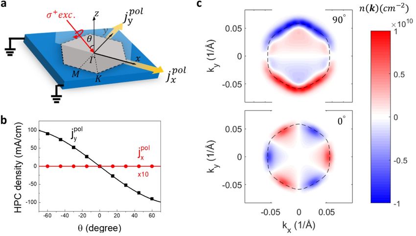
Figure 2. Scattering symmetry-breaking induced HPC. (a) and (b) are the n(k) calculated involving the elastic
scattering from the point and line scatters, respectively. The featured scattering vectors are marked by the arrows
and discussed in the main text. (c) and (d) are the angular distribution of the photocarriers in the k-space for the
point and line potential scattering, respectively. θk is the orientation angle in the k-space as defined in (a, b). (e)
and (f) are real-space angular dependence of the HPC components for the point and line scattering, respectively.
◦
steady-state n(k) for the two types of scatters at θ = 0 . The
point scatter preserves the rotational symmetry and
′ ′ ′ 2 ′′ ′
the scattering is therefore expected to scale with �k |k � . For strict backscattering with k = −k , the initial
and final state of the elastic scattering correspond to a Kramer pair linked by the time-reversal symmetry. Wk′′ ,k′
vanishes due to the orthogonality
′′
of the wavefunctions. Although strict backscattering is forbidden, elastic scat-
tering is allowed for k � = −k 6,7,39. Particularly in the current case of B
i2Te3, the strong hexagonal warping effect
′
leads to the alternating out-of-plane spin texture, promoting the scattering across the hexagonal edge as shown
by the arrows in Fig. 2(a). Since the scattering vectors join the TSSs with similar photocarrier populations, n(k)
is largely unaffected as compared with that in Fig. 1(c), which explains the similar behavior of the HPC. In con-
trast, the line defects scatter carriers anisotropically. While K along the x direction is accommodated by the
scattering potential, K along the orthogonal direction needs to be conserved after the scattering. As a result,
the scattering events are mainly carried out following the solid arrows in Fig. 2(b). The dashed arrow marks the
′ ′ ′ 2
scattering vector that is allowed by the potential but forbidden by �k |k � = 0 . The scattering vectors in
Fig. 2(b) (the solid arrows) connect the TSSs with different populations and thus lead to a redistribution of the
photocarriers. This breaks the three-fold rotation symmetry and generates a primary carrier imbalance along
the kx axis and consequently a new HPC component along the x axis. In Fig. 2(c) and (d) we plot the angular
distribution of the photocarrier in the k-space for point and line scatters, respectively. The angle θk is the angle
in the k-space and is defined counter-clockwise with respect to the k x axis, as shown in Fig. 2(a) and (b). In both
cases, n(θk ) reach local extrema (or zeros) at the angles corresponding to the Ŵ◦ − K (or Ŵ − M ◦
) directions. For
line scattering, an excess population of electrons and holes are found at θk = 0 and θk = 180 . We note that, in
Scientific Reports | (2020) 10:10610 | https://doi.org/10.1038/s41598-020-67612-3 4
Vol:.(1234567890)www.nature.com/scientificreports/
pol
Figure 3. Detection of the out-of-plane spin component. (a) EF dependence of jx for different densities of the
line scatters. The calculation is performed for excitation photon energy of 1.25 eV under the normal incidence
pol
condition. The excitation light polarization is fixed at σ +. (b) jx as a function of different polarization states of
the excitation light. γ is the phase difference between the x - and y-components of the excitation polarization.
pol
The polarization states for different γ are schematically illustrated. (c) Out-of-plane spin polarization Sz for the
carriers contributing to HPC as a function of the Fermi energy, with different densities of the line scatter. The
dashed line shows the energy dependence of the out-of-plane spin texture along the Ŵ − K axis in the k-space.
another aspect, the resulting n(θk ) is also a direct
◦
outcome ◦of the topological protection of the TSSs that the
scattering between the TSSs located at θk = 0 and θk = 180 are forbidden.
In Fig. 2(e) and (f), we compute the HPC density as a function of θ for the two types of scattering centers.
The scattering potential and defect concentration are set at 1.6 eV · Å2 and 1012 cm−240, respectively. The angular
dependence of the HPC in the presence of point scatters is similar to that in Fig. 1(b) where the elastic scatter-
pol
ing is absent. jx remains vanished at all incidence angles, which is consistent with the symmetry ◦constraint. In
pol
sharp contrast, for line scatters, jx develops a finite value, which reaches the maximum at θ = 0 . The angular
dependence of the new HPC component can be nicely fitted by the cosθ function as shown in Fig. 2(f), which
represents the angular dependence of the projection of the photon angular momentum to the orientation of the
out-of-plane spin texture. Although the computed results are for short-range potentials represented by the delta
function, the symmetry consideration should also apply to other types of defects. As a simple test, in Supple-
mentary Note 2, we have considered another two types of scattering potentials, namely the screened Coulomb
potential and spin–orbit coupled scattering potential. We have computed and shown the results for n(k) and
angular dependence of HPC in Supplementary Fig. S3, which yields a consistent result showing that the new
HPC vanishes due to the preserved surface symmetry in other types of scattering centers.
The new HPC component induced by the symmetry-breaking scattering offer new opportunities and a con-
venient and sensitive means not only to optically generate but also to detect the out-of-plane spin component
under the normal incidence condition in a 3D TI. Here, opposite orientations of the out-of-plane spin component
directly lead to opposite directions of the surface photocurrent. This extends the application of the extraden-
tary spin-momentum locking of a 3D TI from only the commonly known in-plane spin c omponent19–23 to the
out-of-plane spin component that is more relevant to the majority of potential spintronic devices that employ
interlayer spin transport. To evaluate the robustness of the approach, we calculate the symmetry-breaking scat-
tering induced HPC as a function of the Fermi level. In Fig. 3(a), we show the results of the computed HPC by
varying EF from − 0.15 eV, when the Fermi level intersects with the bulk valence band at the vicinity of Ŵ point
(8 meV beneath the Dirac point), to 0.15 eV, when the EF reaches the conduction band minimum. The Dirac
point (DP) is located at − 0.142 eV. The tuning range of EF covers both cases when the equilibrium Fermi level
is inside and outside of the bulk bandgap. The calculation is done by considering σ + polarized excitation under
pol
the normal incidence condition. For the selected excitation photon energy of 1.25 eV, jx maintains the positive
sign and would generally be finite due to the aforementioned symmetry consideration regardless of the choice
of EF , which suggests the robustness of the proposed scheme to detect spin generation. As a test, we have calcu-
lated HPC at EF = 0 eV and 0.15 eV where the Fermi level intersects with the bulk valence and conduction band
respectively. The results are shown in Supplementary Fig. S2 for a line defect concentration of 1.0 × 1011 cm−2.
The angular dependence of the resulting HPC is similar to that in Fig. 2, which proves persistence of the new
pol
HPC through a large tuning range of EF . Note that jx can also be chosen to carry a different sign if the character
of the bulk states involved in the optical transition alters by carefully selecting another excitation photon energy.
pol
The amplitude change of the jx with changing EF represents the transitions involving different bands. It is also
pol
clearly seen in Fig. 3(a) that the magnitude of jx , proportional to the detection sensitivity, follows the change
pol
of the line-defect density ni . The jx increases by about two orders of magnitude when ni changes by the same
orders of magnitude, i.e. from 1.0 × 10⁹ to 1.0 × 1011 cm−2. This close correlation confirms the important role
of the symmetry-breaking scattering in HPC. Next, in Fig. 3(b), we show how the new HPC component reacts
to the change of optical spin generation that follows the light helicities changes under the normal incidence
condition. Here, we consider ni = 1.0 × 1011 cm−2 and EF = 0.05eV . γ is the phase different between the x -
and y-component of the excitation polarization and the corresponding polarization states are also illustrated in
pol ◦ ◦
Fig. 3(b). It is evident that jx reverses the sign at γ = 90 and◦ γ = 270 , which corresponds to the optical spin
generation with positive and negative helicities. At γ = 180 , the excitation light becomes linearly polarized
Scientific Reports | (2020) 10:10610 | https://doi.org/10.1038/s41598-020-67612-3 5
Vol.:(0123456789)www.nature.com/scientificreports/
pol
and no spin generation is detected ( jx = 0) as the consequence of the vanishing excitation light helicity, again
demonstrating that HPC is spin dependent.
The spin polarization
of the new HPC
component is found
to depend on the Fermi level, as shown in Fig. 3(c).
pol
By computing Sz = Tr ρ σ + − ρ σ − Sz /Tr ρ σ + − ρ σ − , we demonstrate that the out-of-plane spin polariza-
tion of the photocarriers in the TSSs that contribute to the photocurrent can be adjusted by the Fermi level,
pol
which can for example be conveniently accomplished by applying gate voltage. The as-computed Sz can be tuned
with EF following the energy dependence of the out-of-plane spin texture, which is shown by the dashed line in
Fig. 3(c) regardless of the scattering centers density is altered by two order of magnitude. Such “universal”
pol
behavior of Sz is due to the fast thermalization process, namely the T1 for TSSs in the vicinity of EF is substan-
tially longer than that
at the energies
−1far away from the EF . Since the linearized version of Eq. (2) gives
−1
, it follows that both the overall magnitude of n(k) and the relative
σ+ σ −
elastic
n(k) ∝ G − G γ + T1
contribution of γ elastic are maximized at the EF . As long as this holds, the dominant contribution of the scattering-
pol
driven HPC component ( jx ) is from the TSSs close to the EF . When the EF is tuned through the bulk bandgap
of the B i2Te3, it intersects with TSSs and converts the out-of-plane spin texture of the states into spin-polarized
pol
photocurrent. It is important to note that symmetry-allowed HPC ( jy at a tilted incident angle) does not “ben-
efit” from such thermalization process. This is because the imbalanced distribution of photocarriers are associated
with optical generation. Longer T1 at the EF would make room for momentum relaxation that decreases the HPC.
These results suggest new ways to generate and control the spin photocurrent and its polarization in 3D TIs.
By constructing specific scattering centers that break the C 3v symmetry of the B i2Te3 surface, one can change
both the magnitude and the spin polarization of the HPC. We note that, in the calculations, a simplified scat-
tering potential is assumed, but the qualitative results should also work for more realistic defects: point defects
like charged impurities and vacancies, or line defects such as atomic steps at edges of terraces, twin boundaries,
etc.30,41,42. Bi2Te3 thin films grown on off-cut substrates would be an ideal system to explore such effect. The epi-
taxial growth transfers the texture of the substrate to the surface of the B i2Te3, leading to systematically arranged
atomic steps that can scatter the T SSs21.
In summary, we have theoretically proposed a new way to generate spin polarization and non-equilibrium
spin current in a 3D TI by introducing the symmetry-breaking elastic scattering. The resulting new HPC com-
ponent originates from the out-of-plane spin texture of the TSSs. This new HPC component provides a novel
means for generation and manipulation of the out-of-plane spin polarized photocurrent in 3D TIs, offering new
perspectives for spintronic and opto-spintronic applications exploiting the extraordinary properties of spin-
momentum locking of the 3D TIs.
Received: 13 October 2019; Accepted: 1 June 2020
References
1. Zhang, H. et al. Topological insulators in Bi2Se3, Bi2Te3 and Sb2Te3 with a single Dirac cone on the surface. Nat. Phys. 5, 438–442.
https://doi.org/10.1038/nphys1270 (2009).
2. Xia, Y. et al. Observation of a large-gap topological-insulator class with a single Dirac cone on the surface. Nat. Phys. 5, 398–402.
https://doi.org/10.1038/nphys1274 (2009).
3. Chen, Y. L. et al. Experimental realization of a three-dimensional topological insulator B i2Te3. Science 325, 178–181. https://doi.
org/10.1126/science.1173034 (2009).
4. Wang, L.-L. & Johnson, D. D. Ternary tetradymite compounds as topological insulators. Phys. Rev. B 83, 241309. https://doi.
org/10.1103/PhysRevB.83.241309 (2011).
5. Neupane, M. et al. Topological surface states and Dirac point tuning in ternary topological insulators. Phys. Rev. B 85, 235406.
https://doi.org/10.1103/PhysRevB.85.235406 (2012).
6. Zhou, X., Fang, C., Tsai, W.-F. & Hu, J. Theory of quasiparticle scattering in a two-dimensional system of helical Dirac fermi-
ons: Surface band structure of a three-dimensional topological insulator. Phys. Rev. B 80, 245317. https://doi.org/10.1103/PhysR
evB.80.245317 (2009).
7. Lee, W.-C., Wu, C., Arovas, D. P. & Zhang, S.-C. Quasiparticle interference on the surface of the topological insulator Bi2Te3. Phys.
Rev. B 80, 245439. https://doi.org/10.1103/PhysRevB.80.245439 (2009).
8. Roushan, P. et al. Topological surface states protected from backscattering by chiral spin texture. Nature 460, 1106–1109. https://
doi.org/10.1038/nature08308 (2009).
9. Zhang, T. et al. Experimental demonstration of topological surface states protected by time-reversal symmetry. Phys. Rev. Lett.
103, 266803. https://doi.org/10.1103/PhysRevLett.103.266803 (2009).
10. Pesin, D. & MacDonald, A. H. Spintronics and pseudospintronics in graphene and topological insulators. Nat. Mater. 11, 409–416.
https://doi.org/10.1038/nmat3305 (2012).
11. Fan, Y. & Wang, K. L. Spintronics based on topological insulators. Spin 06, 1640001. https://doi.org/10.1142/S2010324716400014
(2016).
12. Fu, L. & Kane, C. L. Superconducting proximity effect and majorana fermions at the surface of a topological insulator. Phys. Rev.
Lett. 100, 096407. https://doi.org/10.1103/PhysRevLett.100.096407 (2008).
13. Kitaev, A. Y. Fault-tolerant quantum computation by anyons. Ann. Phys. 303, 2–30. https://doi.org/10.1016/S0003-4916(02)00018
-0 (2003).
14. Sinova, J., Valenzuela, S. O., Wunderlich, J., Back, C. H. & Jungwirth, T. Spin Hall effects. Rev. Mod. Phys. 87, 1213–1260. https://
doi.org/10.1103/RevModPhys.87.1213 (2015).
15. Burkov, A. A. & Hawthorn, D. G. Spin and charge transport on the surface of a topological insulator. Phys. Rev. Lett. 105, 066802.
https://doi.org/10.1103/PhysRevLett.105.066802 (2010).
16. Li, C. H. et al. Electrical detection of charge-current-induced spin polarization due to spin-momentum locking in B i2Se3. Nat.
Nanotechnol. 9, 218–224. https://doi.org/10.1038/nnano.2014.16 (2014).
17. Mellnik, A. R. et al. Spin-transfer torque generated by a topological insulator. Nature 511, 449–451. https://doi.org/10.1038/natur
e13534 (2014).
18. Vaklinova, K., Hoyer, A., Burghard, M. & Kern, K. Current-induced spin polarization in topological insulator–graphene hetero-
structures. Nano Lett. 16, 2595–2602. https://doi.org/10.1021/acs.nanolett.6b00167 (2016).
Scientific Reports | (2020) 10:10610 | https://doi.org/10.1038/s41598-020-67612-3 6
Vol:.(1234567890)www.nature.com/scientificreports/
19. McIver, J. W., Hsieh, D., Steinberg, H., Jarillo-Herrero, P. & Gedik, N. Control over topological insulator photocurrents with light
polarization. Nat. Nanotechnol. 7, 96–100. https://doi.org/10.1038/nnano.2011.214 (2012).
20. Kastl, C., Karnetzky, C., Karl, H. & Holleitner, A. W. Ultrafast helicity control of surface currents in topological insulators with
near-unity fidelity. Nat. Commun. 6, 6617. https://doi.org/10.1038/ncomms7617 (2015).
21. Huang, Y. Q., Song, Y. X., Wang, S. M., Buyanova, I. A. & Chen, W. M. Spin injection and helicity control of surface spin photocur-
rent in a three dimensional topological insulator. Nat. Commun. 8, 15401. https://doi.org/10.1038/ncomms15401 (2017).
22. Luo, S., He, L. & Li, M. Spin-momentum locked interaction between guided photons and surface electrons in topological insula-
tors. Nat. Commun. 8, 2141. https://doi.org/10.1038/s41467-017-02264-y (2017).
23. Pan, Y. et al. Helicity dependent photocurrent in electrically gated (Bi1−xSbx)2Te3 thin films. Nat. Commun. 8, 1037. https://doi.
org/10.1038/s41467-017-00711-4 (2017).
24. Kuroda, K. et al. Ultrafast energy- and momentum-resolved surface Dirac photocurrents in the topological insulator S b2Te3. Phys.
Rev. B 95, 081103. https://doi.org/10.1103/PhysRevB.95.081103 (2017).
25. Plank, H. et al. Infrared/terahertz spectra of the photogalvanic effect in (Bi, Sb)Te based three-dimensional topological insulators.
Phys. Rev. Mater. 2, 024202. https://doi.org/10.1103/PhysRevMaterials.2.024202 (2018).
26. Analytis, J. G. et al. Bulk Fermi surface coexistence with Dirac surface state in Bi2Se3: a comparison of photoemission and Shub-
nikov–de Haas measurements. Phys. Rev. B 81, 205407. https://doi.org/10.1103/PhysRevB.81.205407 (2010).
27. Qu, D.-X., Hor, Y. S., Xiong, J., Cava, R. J. & Ong, N. P. Quantum oscillations and Hall anomaly of surface states in the topological
insulator Bi2Te3. Science 329, 821–824. https://doi.org/10.1126/science.1189792 (2010).
28. Checkelsky, J. G., Hor, Y. S., Cava, R. J. & Ong, N. P. Bulk band gap and surface state conduction observed in voltage-tuned crystals
of the topological insulator B i2Se3. Phys. Rev. Lett. 106, 196801. https://doi.org/10.1103/PhysRevLett.106.196801 (2011).
29. Kobayashi, K. Electron transmission through atomic steps of Bi2Se3 and Bi2Te3 surfaces. Phys. Rev. B 84, 205424. https://doi.
org/10.1103/PhysRevB.84.205424 (2011).
30. Zhu, X.-G. et al. Electronic structures of topological insulator B i2Te3 surfaces with non-conventional terminations. New J. Phys.
18, 093015. https://doi.org/10.1088/1367-2630/18/9/093015 (2016).
31. Li, Y.-Y. et al. Intrinsic topological insulator Bi2Te3 thin films on Si and their thickness limit. Adv. Mater. 22, 4002–4007. https://
doi.org/10.1002/adma.201000368 (2010).
32. Pertsova, A. & Canali, C. M. Probing the wavefunction of the surface states in B i2Se3 topological insulator: a realistic tight-binding
approach. New J. Phys. 16, 063022. https://doi.org/10.1088/1367-2630/16/6/063022 (2014).
33. Förster, T., Krüger, P. & Rohlfing, M. GW calculations for B i2Te3 and Sb2Te3 thin films: electronic and topological properties. Phys.
Rev. B 93, 205442. https://doi.org/10.1103/PhysRevB.93.205442 (2016).
34. Hajlaoui, M. et al. Ultrafast surface carrier dynamics in the topological insulator Bi2Te3. Nano Lett. 12, 3532–3536. https://doi.
org/10.1021/nl301035x (2012).
35. Wang, Y. H. et al. Measurement of intrinsic Dirac fermion cooling on the surface of the topological insulator B i2Se3 using time-
resolved and angle-resolved photoemission spectroscopy. Phys. Rev. Lett. 109, 127401. https://doi.org/10.1103/PhysRevLet
t.109.127401 (2012).
36. Boyd, R. W. Nonlinear Optics 2nd edn, 153–162 (Academic Press, London, 2006).
37. Culcer, D., Sekine, A. & MacDonald, A. H. Interband coherence response to electric fields in crystals: Berry-phase contributions
and disorder effects. Phys. Rev. B 96, 035106. https://doi.org/10.1103/PhysRevB.96.035106 (2017).
38. Ganichev, S. D. & Prettl, W. Spin photocurrents in quantum wells. J. Phys.: Condens. Matter 15, R935–R983. https://doi.
org/10.1088/0953-8984/15/20/204 (2003).
39. Wang, J. & Zhu, B.-F. Elastic scattering of surface states on three-dimensional topological insulators. Chin. Phys. B 22, 67301. https
://doi.org/10.1088/1674-1056/22/6/067301 (2013).
40. Sengupta, P. & Bellotti, E. Scattering times and surface conductivity of Dirac fermions in a 3D topological insulator film with
localised impurities. J. Phys. Condens. Matter 27, 405301. https://doi.org/10.1088/0953-8984/27/40/405301 (2015).
41. Hashibon, A. & Elsässer, C. First-principles density functional theory study of native point defects in Bi2Te3. Phys. Rev. B 84,
144117. https://doi.org/10.1103/PhysRevB.84.144117 (2011).
42. Puneet, P. et al. Preferential scattering by interfacial charged defects for enhanced thermoelectric performance in few-layered
n-type Bi2Te3. Sci. Rep. 3, 3212. https://doi.org/10.1038/srep03212 (2013).
Acknowledgements
This work was supported by Linköping University through the Professor Contracts, the Swedish Research Council
(Grant No. 2016-05091), the Swedish Government Strategic Research Area in Materials Science on Functional
Materials at Linköping University (Faculty Grant SFO-Mat-LiU # 2009-00971). Open access funding provided
by Linköping University.
Author contributions
W.M.C. and Y.Q.H. conceived the idea of the paper. Y.Q.H. performed the calculations and analyzed the results
under the guidance from I.A.B. and W.M.C.. Y.Q.H. and W.M.C. wrote the manuscript with contributions from
all authors.
Competing interests
The authors declare no competing interests.
Additional information
Supplementary information is available for this paper at https://doi.org/10.1038/s41598-020-67612-3.
Correspondence and requests for materials should be addressed to Y.Q.H.
Reprints and permissions information is available at www.nature.com/reprints.
Publisher’s note Springer Nature remains neutral with regard to jurisdictional claims in published maps and
institutional affiliations.
Scientific Reports | (2020) 10:10610 | https://doi.org/10.1038/s41598-020-67612-3 7
Vol.:(0123456789)www.nature.com/scientificreports/
Open Access This article is licensed under a Creative Commons Attribution 4.0 International
License, which permits use, sharing, adaptation, distribution and reproduction in any medium or
format, as long as you give appropriate credit to the original author(s) and the source, provide a link to the
Creative Commons license, and indicate if changes were made. The images or other third party material in this
article are included in the article’s Creative Commons license, unless indicated otherwise in a credit line to the
material. If material is not included in the article’s Creative Commons license and your intended use is not
permitted by statutory regulation or exceeds the permitted use, you will need to obtain permission directly from
the copyright holder. To view a copy of this license, visit http://creativecommons.org/licenses/by/4.0/.
© The Author(s) 2020
Scientific Reports | (2020) 10:10610 | https://doi.org/10.1038/s41598-020-67612-3 8
Vol:.(1234567890)You can also read